

TL;DR #
O-rings on conical sealing surfaces with differential pressure exceeding 5 kPa will adsorb to the mating surface during initial hatch opening, and if the seal migrates beyond the groove corner radius contact point (critical position defined at 60° rotation angle), dislodgment becomes inevitable. For procurement engineers specifying subsea hatch seals, inner diameter is the least pressure-sensitive parameter—reducing ID by 10 mm (from 525 to 515 mm in the test case) prevented dislodgment at 13.2 kPa differential while maintaining sealing integrity. Specify O-ring ID using the critical parameter calculation method (based on Hertz contact theory and force balance at α=60°) rather than generic compression guidelines to avoid costly seal loss during underwater operations.
Overview #
Most procurement teams treat O-ring selection for underwater hatches as a straightforward static seal problem, specifying compression ratios from standard catalogs without considering dynamic adsorption forces during the opening sequence. That’s a mistake that causes seal loss in service. Recent field testing at a marine systems research facility evaluated conical hatch seal behavior through finite element simulation validated against instrumented underwater opening trials. The study examined 70 IRHD nitrile rubber O-rings (10 mm cross-section, 525–530 mm ID range) installed on 60° conical sealing surfaces, subjecting them to differential pressures from 5 to 20 kPa while measuring contact stress distribution and seal displacement. Results confirmed that adsorption state is inevitable when pressure differential exists, and seal dislodgment occurs when the O-ring migrates past a calculable critical position where it contacts the groove corner radius. This is not about seal compression—it’s about force balance during transient depressurization, and it requires a fundamentally different qualification approach than most buyers use.
Understanding adsorption mechanics matters because subsea systems—Pump & Valve Seals for hydraulic power units, Sealing & Thermal components in compensator assemblies, and hatch cover systems—all experience transient pressure differentials that standard static seal calculations ignore. The failure mode is binary: either the seal stays in the groove or it doesn’t. There’s no partial dislodgment.
Adsorption State Mechanics Under Differential Pressure #
When a conical hatch begins opening underwater, internal volume increases while the O-ring remains compressed against both the groove sidewall (surface S1) and the conical mating surface (surface S2). Water flows through equalization ports, but during the initial phase, differential pressure Δp acts on the seal cross-section, generating a net force that pulls the O-ring toward the cone apex. This is the adsorption state—the seal moves axially while maintaining contact on both surfaces.
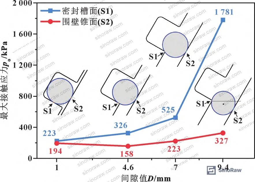
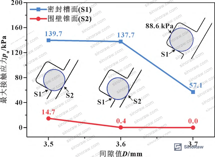
Finite element simulation of a 525 mm ID × 10 mm cross-section O-ring (70 IRHD hardness, 1 mm initial compression on 60° cone) shows maximum contact stress evolution as clearance increases. At 20 kPa differential pressure, contact stress on surface S1 increases monotonically from 0.4 MPa at 1 mm clearance to 0.9 MPa at 4.6 mm clearance. Surface S2 contact stress initially drops from 0.3 MPa to 0.15 MPa (at 3 mm clearance), then rises to 0.35 MPa at 4.6 mm clearance—the point where the seal reaches the groove corner radius.
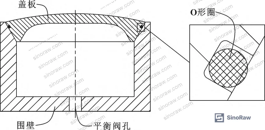
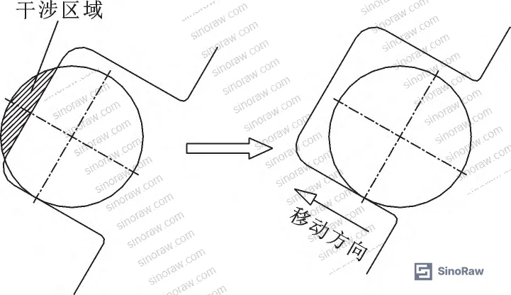
The 4.6 mm clearance position is critical. At this point, the O-ring cross-section center contacts the r₁=0.4 mm corner radius, and rotation about this contact point begins. If contact stress on S2 remains above the differential pressure threshold, adsorption continues and the seal rotates out of the groove. If contact stress falls below Δp, the seal separates from S2, pressure equalizes across both seal faces, and radial elastic force returns the seal to its initial position in the groove.
Testing at 5 kPa differential pressure shows surface S2 contact stress dropping to 0.4 kPa at 3.6 mm clearance—below the 5 kPa threshold. The seal separates from S2 at this point, adsorption state ends, and the seal retracts. At 20 kPa, contact stress never drops below threshold before reaching the corner radius, resulting in continued adsorption, rotation, and eventual dislodgment.
Force Balance Analysis and Critical Position Determination #
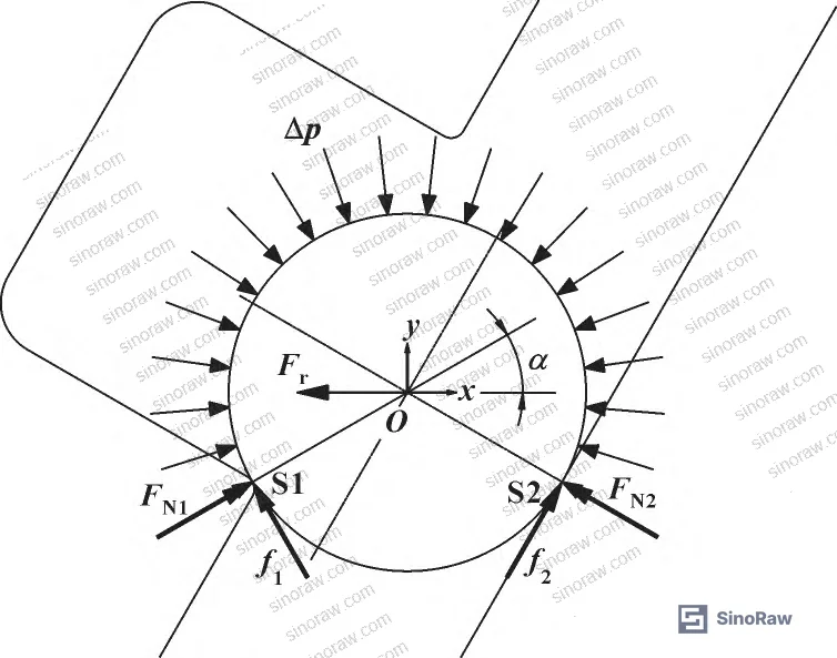
Treating the O-ring cross-section as a circular body with forces acting at the centroid simplifies the analysis while maintaining accuracy for the small deformations observed in adsorption state. Five forces act on the seal: differential pressure Δp distributed over the exposed arc, normal force FN1 and friction f₁ from surface S1, normal force FN2 and friction f₂ from surface S2, and radial elastic force F_r from seal compression.
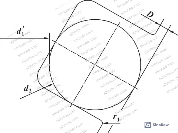
For a 60° conical surface, pressure acts over an arc from -30° to α+180° (where α is the contact angle on S2, ranging from 60° at initial corner contact to 0° when the seal center aligns horizontally with the corner radius). Normal forces FN1 and FN2 act perpendicular to their respective surfaces, with friction forces f₁=0.3FN1 and f₂=0.3FN2 (rubber-on-metal friction coefficient 0.3) acting tangentially. Radial force F_r depends on seal elastic modulus E₀, cross-section diameter d₂, and diametral stretch δ.
The radial force per unit circumference is F_r = πE₀d₂²δ / 2(d₁+d₂)², where stretch δ has two components: linear displacement along the groove sidewall (δ₁ = d’₁ + 2(D-s)cos30° – d₁) and rotational displacement about the corner radius (δ₂ = δ₁ + (d₂/2 – r₁) + (d₂ + 2r₁)(cosα – sin30°)). Here D is clearance, s is initial compression, d₁ is free-state ID, and d’₁ is installed ID.
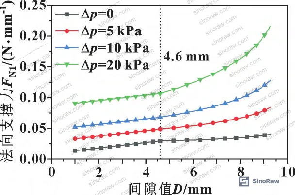
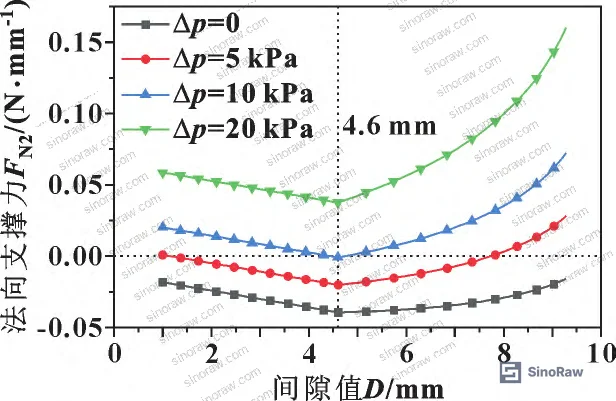
Force equilibrium in x and y directions yields two equations with unknowns FN1 and FN2. Solving these equations for the example geometry (d₁=525 mm, d₂=10 mm, s=1 mm, r₁=0.4 mm, E₀=5.504 MPa for 70 IRHD) at differential pressures of 0, 5, 10, and 20 kPa shows FN1 increases monotonically with clearance for all pressure cases, remaining positive throughout. FN2 initially decreases, reaches minimum at 4.6 mm clearance (α=60°), then increases during rotation. Critically, FN2 minimum value transitions from positive to negative as differential pressure decreases—at 5 kPa, FN2 becomes negative before the seal reaches the corner radius, indicating loss of contact and end of adsorption.
This defines the critical position: α=60° (corner radius contact point). If contact stress at this position exceeds differential pressure, dislodgment will occur. If contact stress is below differential pressure at α=60°, the seal separates from S2 earlier and retracts safely.
Contact Stress Calculation Using Hertz Theory #
Converting normal force F_N2 to contact stress requires accounting for the line contact between the circular O-ring cross-section and the flat conical surface. Because seal deformation remains small during adsorption (less than 5% diametral strain), Hertz contact theory applies despite rubber being a hyperelastic material.
For a cylinder contacting a flat surface, maximum contact stress is p₀ = [2F_N2 · E₀/(πd₂(1-υ²))]^0.5, where υ is Poisson’s ratio (0.4995 for near-incompressible rubber). This formula assumes the mating surface is rigid (valid for steel hatches with E=200 GPa versus rubber E₀=5.5 MPa) and the cylinder radius of curvature is small compared to contact width (valid for 10 mm diameter seal with contact widths under 0.5 mm).
Validation testing compared Hertz formula predictions against finite element results for O-rings at 60, 70, and 80 IRHD hardness under applied loads from 0.1 to 10 N/mm. At low loads (under 1 N/mm), Hertz predictions matched FEA results within 5% for all three hardnesses. At 10 N/mm load, deviation reached 15% for 60 IRHD material but remained under 8% for 70 and 80 IRHD. The divergence at high loads reflects increased deformation violating Hertz small-strain assumptions, but for adsorption state loads (typically 0.3–2 N/mm), agreement is excellent.
According to IEC 62620 Secondary cells and batteries containing alkaline or other non-acid electrolytes and related pressure vessel standards, contact stress verification is required for seals operating under cyclic loading, and the Hertz method provides a rapid analytical check during design iteration without requiring full FEA for every parameter combination.
Critical Parameter Calculation Method #
Setting p₀ = Δp at the critical position (α=60°) and substituting force balance equations yields a single implicit equation F(Δp, E₀, d₂, d₁, s) = 0 relating differential pressure, seal elastic modulus, cross-section diameter, inner diameter, and initial compression. For a given system with known differential pressure (determined by hatch geometry and operating depth), specifying any three of the four seal parameters allows calculation of the fourth parameter’s critical value—the threshold below which dislodgment will not occur.
Honestly, most buyers over-specify cross-section diameter and compression percentage based on static seal practice, then discover during trials that seals fall out during opening. The correct approach is to calculate critical ID for the actual operating differential pressure, then select the next smaller standard size.
The table below shows calculated critical parameter values for a 60° conical hatch with 0.4 mm groove corner radius, varying differential pressure from 5 to 20 kPa:
| Variable Parameter | Fixed Parameters | Critical Value at 5 kPa | Critical Value at 10 kPa | Critical Value at 20 kPa | Sensitivity Rank |
|---|---|---|---|---|---|
| Hardness (IRHD) | d₁=525 mm, d₂=10 mm, s=1 mm | 54.2 | 69.3 | 85.4 | 3 (moderate) |
| Inner diameter d₁ (mm) | 70 IRHD, d₂=10 mm, s=1 mm | 530.8 | 525.3 | 515.0 | 4 (lowest) |
| Cross-section d₂ (mm) | 70 IRHD, d₁=525 mm, s=1 mm | 6.6 | 9.8 | 14.6 | 2 (high) |
| Compression s (mm) | 70 IRHD, d₁=525 mm, d₂=10 mm | 4.4 | 1.2 | -5.3 | 1 (highest) |
The compression parameter sensitivity is highest—increasing differential pressure from 5 to 20 kPa drives the critical compression from 4.4 mm (44% compression, which would destroy the seal) to a physically meaningless negative value. Cross-section diameter sensitivity is also problematic, requiring 14.6 mm cross-section at 20 kPa, which exceeds standard O-ring proportions and creates groove design conflicts.
Inner diameter shows the lowest sensitivity: a 15.8 mm ID reduction (530.8 to 515.0 mm, only 3% change) accommodates a 4× increase in differential pressure. This is the design variable to adjust. Hardness is moderately sensitive but limited by material availability—seals softer than 60 IRHD lack abrasion resistance, while seals harder than 80 IRHD exhibit poor low-temperature flexibility. Most subsea applications standardize on 70 IRHD nitrile for this reason, making hardness adjustment impractical.
The critical parameter method requires iterative numerical solution because the equation contains nonlinear terms (trigonometric functions, square roots from Hertz stress formula, and elastic force stretch terms). MATLAB or equivalent software is necessary to maintain precision—approximating cos(30°) as 0.866 instead of the exact value introduces 0.2% error that propagates through the calculation and can shift the critical ID by several millimeters.
For buyers sourcing seals for existing hatch designs, the process is: measure actual differential pressure during opening (using pressure transducers on both sides of the hatch), fix cross-section diameter and compression based on groove geometry, set hardness at 70 IRHD, and solve for critical ID. Then specify ID at least 5–10 mm smaller than the critical value to provide margin against variability in rubber properties, surface finish, and assembly tolerance.
Practical Guidance for Buyers #
When qualifying O-ring suppliers for conical hatch seals, demand test data, not certifications. Request finite element simulation results showing contact stress distribution at the critical position for your specific geometry and operating pressure. If the supplier cannot provide this, they don’t understand the failure mode and you’ll waste time with trials that fail.
Second, verify elastic modulus through compression testing, not hardness measurement alone. The conversion formula (log E₀ = 0.0187Hr – 0.5670, where E₀ is in MPa and Hr is IRHD) is empirical with ±15% scatter. A 70 IRHD seal with modulus at the low end of the tolerance band (4.7 MPa instead of 5.5 MPa) has 12% lower radial force, shifting the critical ID by 7–8 mm. Insist on modulus certification or perform your own compression testing during incoming inspection.
Third, control groove corner radius tightly. The r₁=0.4 mm radius in the example is common for machined aluminum or steel parts, but if manufacturing allows radius to grow to 0.8 mm, the critical position shifts and the seal contacts the corner earlier during adsorption, reducing the margin before dislodgment. Specify corner radius as 0.4 +0.1/-0 mm and verify it with radius gauges during first article inspection.
Fourth, don’t assume that increasing initial compression improves retention. The table above shows compression has the worst sensitivity—higher compression increases contact stress in the static state but provides no benefit during adsorption because differential pressure and elastic force dominate the force balance. Excessive compression (above 15%) causes stress relaxation and permanent set, degrading sealing performance over repeated cycles. Stick to 8–12% compression and adjust ID instead.
For buyers working with Chinese manufacturers of Industrial Hose assemblies and Fluid Control components where subsea seals are integrated into larger systems, the critical parameter method allows you to specify ID tolerance based on actual operating conditions rather than generic catalog recommendations. At SinoRaw, we help overseas procurement teams identify suppliers who can perform this type of application-specific seal analysis and provide the supporting calculations and test data as part of the quotation package. Most factories stamp O-rings into grooves based on what fits, not what works under transient pressure differentials—having these calculations in hand before issuing the RFQ separates capable suppliers from order-takers.
Need help identifying qualified suppliers for conical hatch O-rings with verified critical parameter calculations? Talk to our sourcing team →
Experimental Validation Through Underwater Opening Trials #
Validation testing used a prototype wet-dry conversion system with conical hatch cover matching the analysis geometry (60° cone, 0.4 mm corner radius, 10 mm × 525 mm nominal O-ring). A depth gauge installed inside the hatch recorded 0.68 m water depth before opening and -0.64 m after equalization, yielding 13.2 kPa differential pressure. Applying the critical parameter calculation with d₂=10 mm, s=1 mm, and E₀=5.504 MPa (70 IRHD) gives critical ID of 521.9 mm.
Two O-rings were tested: 525 mm ID (3.1 mm above critical value) and 515 mm ID (6.9 mm below critical value). The 525 mm seal dislodged from the groove during opening and was recovered floating in the test tank. The 515 mm seal exhibited visible adsorption (shifted position in groove) but did not dislodge, retracting to near its initial position after pressure equalization. Post-test inspection showed no damage to either seal.
This bracketing test confirms two critical findings: (1) the calculated critical ID value of 521.9 mm accurately predicts the transition between safe retention and dislodgment, and (2) a 10 mm margin below critical (515 vs 521.9 mm) provides sufficient safety factor for parameter variability. The 525 mm seal failure was not marginal—it was a complete ejection, not a partial displacement that might self-correct. Similarly, the 515 mm seal retention was robust, with adsorption displacement limited to approximately 2 mm based on witness marks in the groove.
The test also validated the force balance model’s prediction that adsorption state occurs whenever differential pressure exists. Both seals showed evidence of movement during the initial opening phase, but only the seal above the critical ID threshold continued movement to the point of dislodgment. This confirms that adsorption cannot be eliminated through surface finish, lubrication, or other friction-reduction methods—it is a consequence of pressure differential acting on the seal cross-section and must be accommodated through correct parameter selection.
Supplier Qualification Questions #
- What is the measured initial elastic modulus E₀ (MPa) for your 70 IRHD nitrile compound, and can you provide compression stress-strain data at 10%, 15%, and 20% strain to verify the value falls within 5.0–6.0 MPa range specified for critical parameter calculations?
- For a 60° conical sealing surface with 13.2 kPa maximum operating differential pressure, what inner diameter do you specify for a 10 mm cross-section O-ring with 1 mm initial compression and 0.4 mm groove corner radius to ensure contact stress at α=60° critical position remains below the dislodgment threshold?
- Can you provide finite element simulation results showing contact stress distribution on both the groove sidewall (surface S1) and conical mating surface (surface S2) for the specified seal geometry at clearance values from 1 mm to 5 mm, with validation that surface S2 contact stress drops below differential pressure before reaching the corner radius contact point?
- What corner radius tolerance do you maintain on machined seal grooves for conical hatch applications, and how do you verify compliance during first article inspection—the critical parameter calculation assumes r₁=0.4 mm with +0.1/-0 mm tolerance?
- Have you conducted underwater opening trials with pressure differential measurement and high-speed video documentation to verify that O-rings remain captured in grooves throughout the opening sequence, and can you provide the test matrix showing combinations of differential pressure, seal ID, and hardness that were validated?
Sourcing Checklist #
- ☐ Supplier provides certified stress-strain data for rubber compound showing initial elastic modulus E₀ within ±10% of nominal value calculated from IRHD hardness using conversion formula log E₀ = 0.0187H_r – 0.5670
- ☐ Critical inner diameter d₁ calculated for maximum operating differential pressure Δp using force balance equation F(Δp, E₀, d₂, d₁, s)=0 solved numerically to ensure contact stress at α=60° position equals or slightly exceeds Δp
- ☐ Specified O-ring ID is at least 5 mm smaller than calculated critical ID value to provide margin for material property variation and assembly tolerance
- ☐ Groove corner radius verified as 0.4 mm +0.1/-0 mm using radius gauge or CMM measurement during first article inspection
- ☐ Initial compression s limited to 8–12% of cross-section diameter d₂ (0.8–1.2 mm for 10 mm cross-section) to avoid excessive stress relaxation while maintaining adequate sealing force
- ☐ Finite element simulation results provided showing surface S2 contact stress drops below operating differential pressure before seal cross-section center reaches corner radius contact point at clearance = (d₂/2 – r₁)/sin(30°)
- ☐ Underwater opening trial data available documenting successful seal retention under differential pressure equal to or exceeding maximum operating value for the specified seal geometry
- ☐ Material certification confirms compound meets ISO 12405-4 Electrically propelled road vehicles — Test specification for lithium-ion traction battery packs and systems requirements for seal elastomers in pressure differential applications if applicable to system classification
Key Specifications Table #
| Parameter | Recommended Value | Verification Method |
|---|---|---|
| Inner diameter d₁ (mm) | ≤ (Critical ID – 5 mm), where Critical ID calculated from F(Δp, E₀, d₂, d₁, s)=0 at α=60° | Dimensional inspection per ISO 3601-1, verify installed ID d’₁ = d₁(1 + stretch rate) matches groove diameter within ±0.5 mm |
| Cross-section diameter d₂ (mm) | 10 mm for hatches 500–600 mm diameter; maintain d₂/d₁ ratio 0.015–0.025 | Caliper measurement at 4 points 90° apart, maximum deviation ±0.2 mm per ISO 3601-1 |
| Initial compression s (mm) | 0.8–1.2 mm (8–12% of d₂) for static seal | Measure groove depth and seal cross-section; verify s = (groove depth – d₂) falls in range |
| Elastic modulus E₀ (MPa) | 5.0–6.0 for 70 IRHD nitrile; verify via compression test | ASTM D575 compression testing at 10% and 20% strain, calculate secant modulus, confirm ±10% of nominal |
| Groove corner radius r₁ (mm) | 0.4 +0.1/-0 mm | Radius gauge or CMM verification, maximum 0.5 mm to prevent premature corner contact |
| Contact stress at critical position (MPa) | p₀ ≤ 0.95 × Δp when α=60° | Calculate using Hertz formula p₀ = [2FN2·E₀/(πd₂(1-υ²))]^0.5 with FN2 from force balance at clearance D = (d₂/2 – r₁) |
Can’t find a supplier meeting these specs? Submit your requirements and we’ll match you within 48 hours.
References #
Data source: Adsorption State and Dislodgment Analysis of O-Rings on Conical Sealing Surfaces in Underwater Opening Applications, M. Yuan et al., Lubrication Engineering, 2025
Frequently Asked Questions #
Why does adsorption occur even with proper initial compression?
Adsorption is caused by differential pressure acting on the seal cross-section exposed between the groove sidewall and conical mating surface, not by inadequate compression. Even a heavily compressed seal will adsorb if pressure differential exists during opening because the net force from Δp acting over the exposed arc area exceeds the frictional resistance from contact surfaces. Initial compression affects static sealing performance but has minimal impact on adsorption behavior—the force balance during opening is dominated by differential pressure and elastic force, not by preload.
Can increasing surface finish or using lubricant prevent dislodgment?
No. Reducing friction coefficient from 0.3 to 0.1 through lubrication changes the force balance slightly but does not eliminate adsorption state or prevent dislodgment if the seal geometry is above the critical parameter threshold. The simulation and test results show that once the seal reaches the corner radius contact point with sufficient contact stress, rotation and dislodgment follow regardless of friction. Surface finish and lubrication are important for minimizing seal wear and ensuring smooth movement, but they cannot substitute for correct ID selection.
What happens if the calculated critical ID is smaller than available standard O-ring sizes?
This indicates the operating differential pressure is too high for the groove geometry, requiring either groove redesign to accommodate a smaller standard size or system modification to reduce differential pressure. Common solutions include adding staged equalization ports to limit maximum Δp during opening, increasing groove depth to allow a larger cross-section seal (which lowers the critical ID for a given Δp), or switching to a custom O-ring size. Do not specify an ID above the critical value hoping that “it might work”—the test data shows the failure is deterministic, not probabilistic.
Why is the 60° contact angle the critical position rather than 0° when the seal is most rotated?
The critical position is where the seal first contacts the groove corner radius (α=60° for a 60° cone), because this is the last point where the seal can still separate from surface S2 and retract due to radial elastic force. Once the seal rotates past α=60°, it wraps around the corner radius and the geometry prevents retraction even if contact stress drops below differential pressure. At α=0° (seal center aligned horizontally with corner center), the seal has already dislodged and is only held by friction on surface S1—there is no recovery path from this position. The critical position analysis identifies the decision point where retention versus dislodgment is determined.
How does temperature affect the critical parameter calculation?
Temperature changes rubber elastic modulus E₀, which directly impacts radial force F_r and therefore the critical ID calculation. For nitrile rubber, E₀ decreases approximately 20–30% from 20°C to 60°C and increases 50–80% from 20°C to -20°C. In cold subsea environments (near 0°C), higher modulus means greater radial force and lower critical ID requirement—the seal is less prone to dislodgment. In warm hydraulic systems (above 40°C), lower modulus increases critical ID and dislodgment risk. For systems operating over wide temperature ranges, calculate critical ID at the highest operating temperature (lowest modulus, worst case) and verify adequate margin.
Published by sinoraw.com Technical Team | Request a sourcing quote


