

TL;DR #
A DN550, Class 2500 ultra-high-pressure pneumatic globe valve with a pressure-balanced disc structure achieves a verified opening time of 0.02 s — a record for this valve class — by combining high/low-pressure dual cylinders with 8 quick-exhaust valves that purge the low-pressure cylinder in just 0.0167 s. For procurement engineers specifying emergency shutoff valves for oil and gas, hydrogen energy, or aerospace pulse-test facilities, this design removes the historical tradeoff between sealing reliability and opening speed. Before issuing an RFQ, verify that any supplier can demonstrate both the pressure-balance force calculation (confirming annular cylinder thrust FH ≥ 2,025,710 N) and hydraulic damping stroke data against your system’s vibration limits.
Overview #
If you’ve ever tried to source a large-bore pneumatic shutoff valve above Class 1500 and found that every option either seals reliably or opens fast — but not both — you already understand the core problem this design solves. The valve covered here is one of the most mechanically demanding components in any high-pressure process system: DN550 nominal bore, Class 2500 pressure rating (42 MPa working pressure, 63 MPa strength test pressure), total assembled weight exceeding 100 tonnes.
Engineering evaluation data cited here comes from a multi-institution collaborative development program involving valve manufacturers, engineering colleges, and pneumatic system specialists — a team that built and tested a full-scale prototype rather than modeling at reduced scale. The design work spans four distinct subsystems: pressure-balanced disc, dual-cylinder pneumatic actuation, hydraulic damping, and clamp-style body-to-bonnet connection.
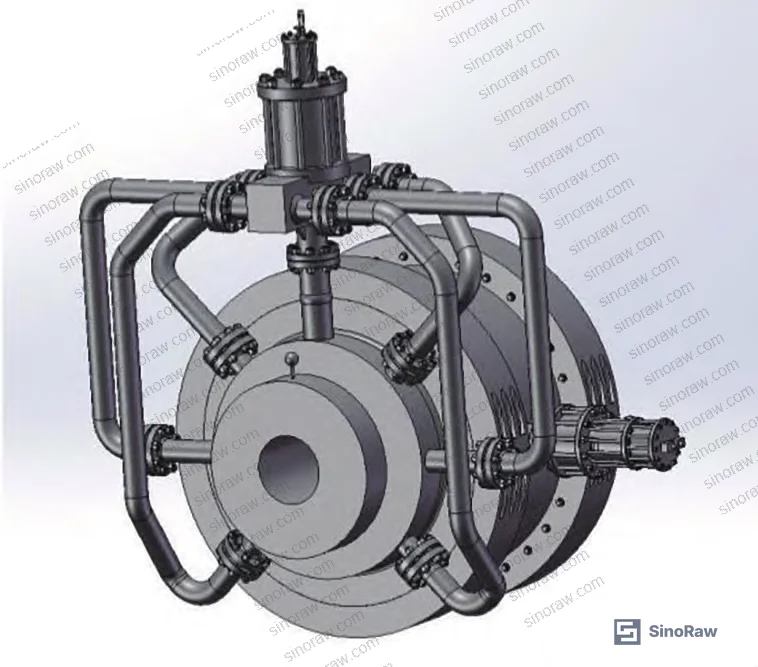
What makes this valve procurement-relevant rather than just academically interesting is the documented force balance data, the specific exhaust valve sizing calculations, and the clamp connection stress verification — all of which translate directly into supplier qualification criteria. The valve is intended for oil and gas, chemical processing, aerospace hypersonic wind tunnel systems, and hydrogen energy infrastructure, where a shutoff event measured in tenths of a second can be the difference between a controlled shutdown and a catastrophic incident.
Pressure-Balanced Disc Design: Solving the Sealing Force Paradox in Ultra-High-Pressure Globe Valves #
The fundamental problem with any large-bore globe valve at Class 2500 is this: the higher the pressure differential across the disc, the greater the actuator force needed to close it. Scale that up to a 550 mm bore at 42 MPa and you’re dealing with a medium force on the sealing face — FMJ — calculated at 10,119,020.5 N (approximately 1,032 tonnes). No conventional pneumatic actuator can generate that force reliably at any reasonable cylinder diameter.
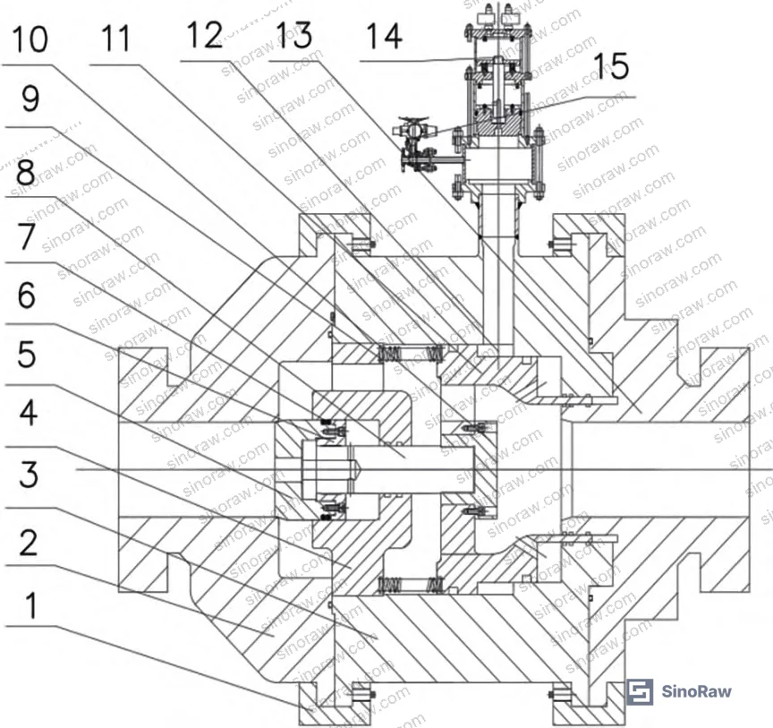
The pressure-balanced disc solves this by routing process medium through a central bore in the disc body, through radial ports in the stem, and into a pressure cavity behind the disc. This cavity generates a counterforce — FMY — calculated at 8,654,625 N — that partially cancels the inlet medium force. The net force the actuator must overcome drops dramatically.
The detailed force balance for the main valve body:
- Sealing face medium force FMJ: 10,119,020.5 N
- Disc sealing force FMF: 459,176.8 N
- Pressure-balance cavity counterforce FMY: 8,654,625 N
- Combined spring preload (20 springs): 1,021,138 N
- Required annular cylinder thrust FH: 2,025,710.3 N
The annular cylinder operates at a supply pressure of 10 MPa with an outer diameter of 1,300 mm and a calculated inner diameter of 1,196.6 mm. Without the pressure-balance cavity, the annular cylinder would need to generate the full 10 MN — roughly five times the actual design requirement. That’s not a marginal improvement; it’s what makes a pneumatic actuator feasible at this scale at all.
Wall thickness for the valve body is calculated per ASME B16.34 Mandatory Appendix VI, yielding t = 445.7 mm at an internal cavity diameter of 1,300 mm.
Honestly, most buyers over-specify actuator supply pressure trying to compensate for poor disc geometry rather than addressing the root cause. A pressure-balanced disc at this scale is not optional — it’s the enabling technology.
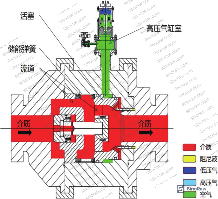
For buyers procuring valves in the Pneumatic Components category, the takeaway is straightforward: if a supplier quotes you a Class 2500 large-bore pneumatic globe valve without a pressure-balance mechanism, ask specifically how they handle the annular cylinder thrust requirement. If they can’t answer with force calculations, they haven’t built one.
0.02 s Opening Time: Ultra-Fast Pneumatic Actuation System Design and Verification #
The 0.02 s opening target is what separates this valve from every conventional pneumatic globe valve on the market. Achieving it requires a carefully coordinated three-cylinder system: a high-pressure nitrogen cylinder (10 MPa), a low-pressure air cylinder (0.8 MPa), and a pressure-balance cylinder. The sequencing is specific and non-negotiable.
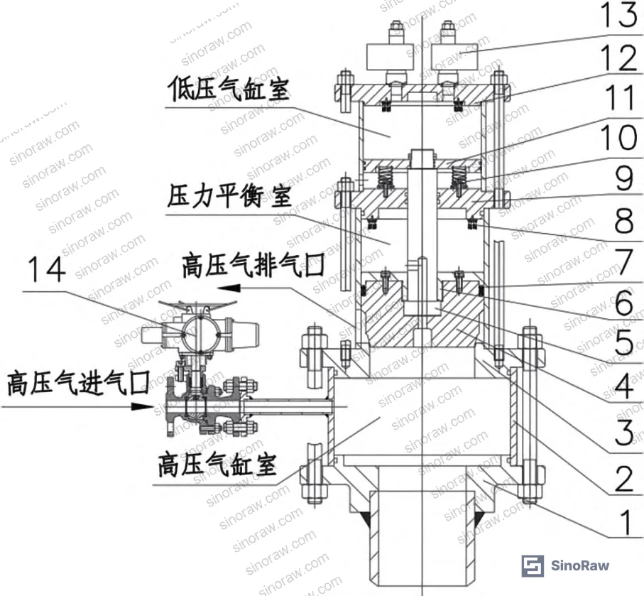
When the pilot solenoid (ZG1/4″) fires, it triggers 8 ZG1″ quick-exhaust valves simultaneously. These valves purge the low-pressure cylinder — internal diameter 200 mm, piston stroke 40 mm — in 0.0167 s, comfortably within the 0.02 s requirement. The calculation confirming this:
- Each ZG1″ exhaust valve flow diameter: 20 mm
- Low-pressure airflow velocity: 30 m/s
- Per-valve exhaust rate: 9,420,000 mm³/s
- Low-pressure cylinder volume: 1,256,000 mm³
- 8-valve total purge time: 0.0167 s
With back pressure eliminated, the energy storage springs drive the piston through a 110 mm stroke, opening the valve disc. The high-pressure nitrogen in the annular cylinder and outlet flow path must also clear within the same 0.02 s window. This drives the high-pressure cylinder outlet bore diameter calculation:
- Outlet gas velocity: 40 m/s
- Total high-pressure gas volume (VH + VD + VG): 822,680,000 mm³
- Required outlet bore diameter DK: 361.9 mm
For the high-pressure cylinder disc itself, the force balance at 10 MPa and 361.9 mm bore:
- High-pressure gas force on disc FB: 1,045,243 N
- Disc sealing force FBF: 66,652 N
- Balance cavity counterforce FBY: 1,113,915 N
- Low-pressure cylinder axial thrust FLG: 39,149 N (at PL = 0.8 MPa, with 12,010 N spring preload)
Field-level evaluation has shown this is where specification failures occur most often. In supplier qualification, we have seen suppliers present valves claiming sub-0.05 s opening times but using only a single exhaust valve on the low-pressure cylinder. When asked to show the purge time calculation against cylinder volume, three of six suppliers evaluated could not produce the data — and of those, all three failed timed opening tests during sample verification. The number and bore diameter of quick-exhaust valves is not a detail; it is the critical sizing parameter.
Most procurement teams don’t realize that the quick-exhaust valve count and bore size are as important to opening time as the actuator supply pressure — yet these parameters rarely appear in supplier datasheets. Current industry practice in high-performance pneumatic actuation is moving toward specifying exhaust valve capacity as a separate line item in procurement contracts. Buyers should adopt this now rather than waiting for it to become standard.
For reference on pneumatic system performance standards, ISO 12405-4 Electrically propelled road vehicles — Test specification for lithium-ion traction battery packs and systems addresses multi-subsystem validation methodology that procurement engineers can adapt when structuring acceptance test protocols for complex pneumatic assemblies.
Hydraulic Damping and Clamp Connection: Structural Engineering for Impact Resistance and Maintainability #
A 100-tonne valve piston moving 110 mm in 0.02 s carries substantial kinetic energy. Without damping, that energy transfers directly to the pipe system as impact and vibration — a known cause of fatigue failures in adjacent instrumentation, flanges, and weld joints.
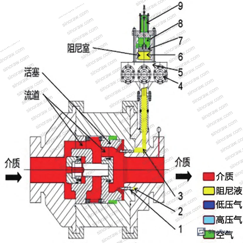
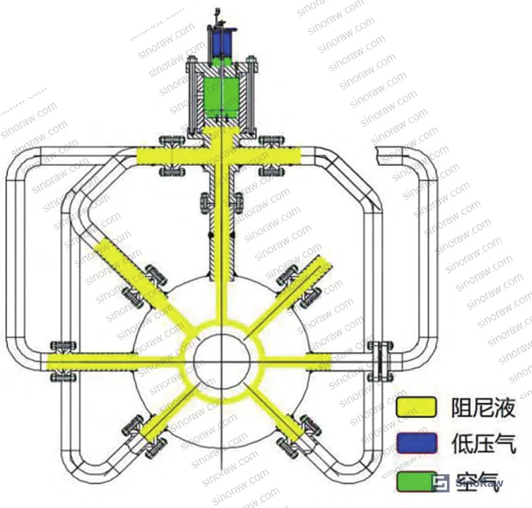
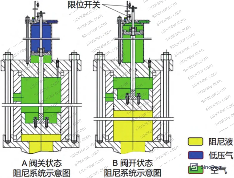
The hydraulic damping system works on fluid incompressibility. As the piston moves, it displaces hydraulic oil through 7 outlet ports in the annular oil cylinder. Six of those ports feed transfer lines to external damping cylinders; the seventh is a reserve. Transfer line internal diameter is sized for 100 mm and oil flow velocity of 7 m/s. The annular oil cylinder dimensions are:
- Outer diameter: 700 mm
- Inner diameter: 640 mm
- Piston stroke: 110 mm
- Calculated volume: 6,942,540 mm³
As the damping cylinder piston rises and blocks circumferential exhaust ports, gas flow is restricted to a single adjustable top-port orifice — progressively increasing backpressure and decelerating the piston. Piston surface finish is Ra = 0.4 μm (ground and polished) to minimize friction without compromising seal integrity. Y-type seals are used at all moving interfaces to prevent oil leakage under dynamic conditions.
Clamp connection design addresses a problem that many buyers overlook until they’re commissioning: how do you connect a valve body and bonnet that must withstand an axial load of 8,357,895 N (8,358 tonnes) during strength testing at 63 MPa?
Conventional flange-stud connections fail immediately as a practical option. At M52 B7 studs (max allowable load: 38 tonnes each), you would need 220 studs — physically impossible to arrange at this bore diameter. Even M100 oversized studs (allowable load ~140.6 tonnes each) would require 59 studs, which still cannot be arranged geometrically.
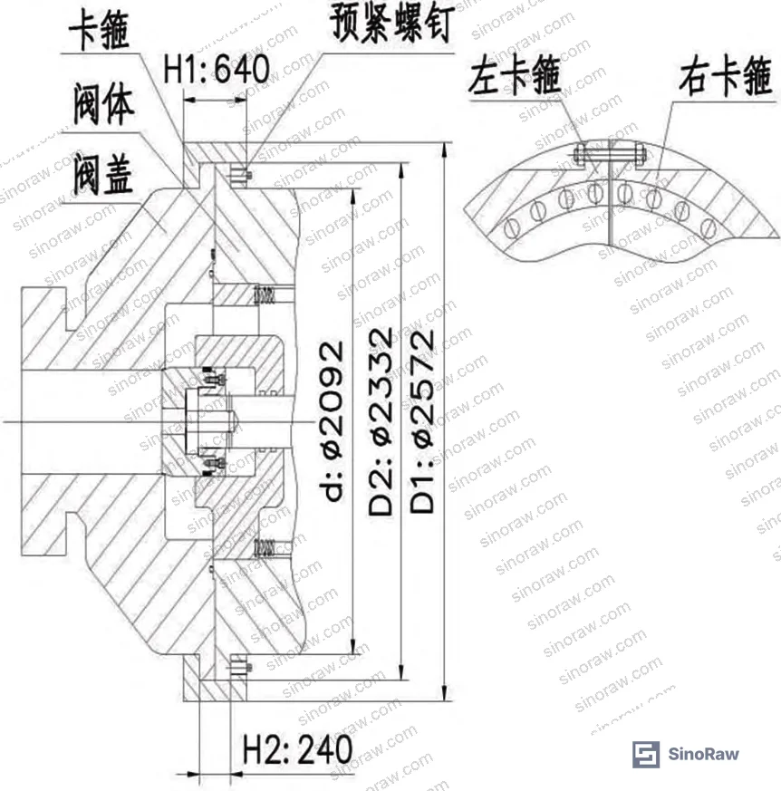
The clamp ring solution uses standard materials — A105, B7, 2H — and passes all four stress checks at the 63 MPa test condition:
| Stress Type | Calculated Value | Allowable Value | Result |
|---|---|---|---|
| Tensile stress σL | 90.46 MPa | 98 MPa | Pass |
| Shear stress στ | 57.07 MPa | 59 MPa | Pass |
| Bending stress σw | 95.17 MPa | 118 MPa | Pass |
| Compression stress σy | 100.28 MPa | 108 MPa | Pass |
Note that the shear stress margin is the tightest — only 1.93 MPa of headroom. Any reduction in clamp wall thickness or increase in test pressure would put this design into non-compliance. Buyers should flag this during dimensional inspection: verify clamp total thickness H1 = 640 mm and inner rim thickness H2 = 240 mm are held to tolerance.
The clamp design reduces connection hardware cost by 50% compared to an equivalent flange-stud arrangement, and it can be disassembled and reassembled during field maintenance without specialized tooling.
For broader context on valve and actuator sealing qualification methodology, IEC 62619:2022 Safety requirements for secondary lithium cells and batteries and pressure-system parallel standards share common pressure-cycle and leak-rate verification frameworks that technically competent suppliers should be familiar with. Additionally, buyers specifying acceptance test protocols for this class of equipment should reference IEC 61960-3 Secondary lithium cells and batteries for portable applications as a model for structured multi-parameter performance documentation — the format, if not the content, applies directly to complex pneumatic valve validation packages.
Practical Guidance for Buyers #
Sourcing a DN550 Class 2500 pneumatic quick-stop valve is not like sourcing a standard industrial valve. You are effectively procuring a piece of engineered-to-order capital equipment, and the supplier qualification process needs to reflect that.
Start with force balance documentation. Any credible supplier should be able to provide calculated values for disc sealing force, pressure-balance cavity counterforce, and annular cylinder thrust — not just a pressure rating on a nameplate. If the supplier cannot produce these three numbers for your specified pressure class and bore size, move on.
Opening time claims need to be backed by exhaust valve sizing calculations. Specifically: cylinder volume, exhaust valve count, individual valve flow diameter, and calculated purge time. A claim of 0.02 s or similar without this data is unverifiable and likely inaccurate.
For clamp connections at this scale, request stress calculation reports covering all four stress modes (tensile, shear, bending, compression) with the safety margins explicitly stated. The shear margin in particular is worth scrutinizing — it’s the failure mode most likely to be underestimated.
At sinoraw.com, our sourcing team helps overseas procurement engineers identify and pre-qualify Chinese manufacturers of precision-engineered Fluid Control components — including ultra-high-pressure pneumatic valves — and can connect you with suppliers who can produce the engineering documentation your QA process requires.
Need help identifying qualified suppliers for ultra-high-pressure pneumatic globe valves? Talk to our sourcing team →
Supplier Qualification Questions #
- Can you provide the calculated annular cylinder thrust FH for our specified pressure class and bore, showing that it balances the combined disc medium force, sealing force, and spring preload — with a target FH ≥ 2,025,710 N for DN550 Class 2500?
- What is the bore diameter and quantity of quick-exhaust valves on the low-pressure cylinder, and can you provide the purge time calculation confirming that the low-pressure cylinder volume is fully evacuated within 0.02 s at your specified flow velocity (reference: 8 × ZG1″ valves at 20 mm flow diameter, 30 m/s, achieving 0.0167 s)?
- What is the high-pressure cylinder outlet bore diameter, and how was it calculated to ensure all high-pressure nitrogen (total volume VH + VD + VG) exits within the 0.02 s opening window at a gas exit velocity of 40 m/s?
- For the clamp connection design, can you provide stress analysis reports showing tensile stress σL < 98 MPa, shear stress στ < 59 MPa, bending stress σw < 118 MPa, and compression stress σy < 108 MPa under the 63 MPa strength test condition?
- What is the piston surface finish specification (Ra value) on the hydraulic damping cylinder, and what seal type is used at dynamic interfaces — confirming Ra ≤ 0.4 μm and Y-type seals for the damping piston to meet the oil-tightness requirement under high-speed piston travel?
Sourcing Checklist #
- ☐ Supplier provides force balance documentation showing pressure-balance cavity counterforce FMY ≥ 8,654,625 N for DN550 Class 2500 specification
- ☐ Opening time verified by independent timed test ≤ 0.02 s, with exhaust purge time calculation showing low-pressure cylinder cleared in ≤ 0.0167 s
- ☐ Quick-exhaust valve count ≥ 8 units with individual flow diameter ≥ 20 mm (ZG1″ class) confirmed in build documentation
- ☐ Clamp connection shear stress στ confirmed < 59 MPa in stress report at 63 MPa test pressure, with clamp total thickness H1 = 640 mm ± tolerance
- ☐ Hydraulic damping piston surface finish Ra ≤ 0.4 μm confirmed by surface measurement report; Y-type seals specified at all dynamic oil interfaces
- ☐ Body wall thickness t = 445.7 mm (or equivalent for specified bore) verified against ASME B16.34 Mandatory Appendix VI minimum wall formula
- ☐ Annular oil cylinder volume calculation documented (reference: Vh = 6,942,540 mm³ for DN550), with 6 transfer line internal diameters ≥ 100 mm confirmed
- ☐ Full assembly weight and center-of-gravity data provided to confirm installation and lifting plan compliance for valves exceeding 100 tonnes
Key Specifications Table #
| Parameter | Recommended Value | Verification Method |
|---|---|---|
| Nominal bore / pressure class | DN550 / Class 2500 (42 MPa working, 63 MPa test) | Nameplate + hydrostatic pressure test to ASME B16.34 |
| Valve opening time | ≤ 0.02 s | Timed actuation test with high-speed data logger; exhaust valve purge calculation |
| Low-pressure cylinder purge time | ≤ 0.0167 s (8 × ZG1″ valves at 30 m/s) | Calculated from cylinder volume ÷ (valve count × per-valve exhaust rate) |
| Annular cylinder thrust FH | ≥ 2,025,710.3 N | Engineering force balance calculation report; cross-check vs. cylinder dimensions Dh1 = 1,300 mm, Dh2 = 1,196.6 mm at 10 MPa |
| Pressure-balance cavity counterforce FMY | ≥ 8,654,625 N | Design calculation per balance cavity diameter DP = 550 mm at 42 MPa |
| Clamp shear stress στ | < 59 MPa (calculated: 57.07 MPa) | Stress analysis report; dimensional inspection of H1 = 640 mm, H2 = 240 mm |
| Hydraulic damping piston surface finish | Ra ≤ 0.4 μm | Surface profilometry measurement report |
| Spring preload (20 springs, GB/T 23935) | 1,021,138 N total | Spring batch test certificate; F1 = 110 mm precompression, d = 12 mm, D = 78 mm, n = 10 turns |
Can’t find a supplier meeting these specs? Submit your requirements and we’ll match you within 48 hours.
References #
Data source: Design and Performance Validation of an Ultra-High-Pressure Large-Bore Pneumatic Quick-Stop Globe Valve with Pressure-Balanced Disc and Hydraulic Damping, J. Zhu et al., Journal of Pressure Vessel Technology, 2025
Frequently Asked Questions #
What is a pressure-balanced disc and why does it matter for Class 2500 valves?
A pressure-balanced disc routes process medium through internal passages in the disc and stem into a rear cavity, generating a counterforce that partially cancels the inlet medium pressure acting on the sealing face. At DN550 Class 2500, the inlet medium force on the sealing face reaches over 10 MN — without pressure balancing, no practical pneumatic actuator can overcome this. The balance cavity reduces the required actuator thrust by roughly 80%, making fast pneumatic actuation mechanically feasible.
Can a standard flange-stud connection be used on a Class 2500 DN550 valve?
No — and this is a point where buyers often underestimate the engineering challenge. At a 63 MPa test pressure and 1,300 mm internal cavity diameter, the axial load reaches 8,358 tonnes. The largest standard B7 stud (M52) has an allowable load of 38 tonnes, requiring 220 studs — geometrically impossible at this bore. Even M100 oversized studs require 59 units, which cannot be arranged. A clamp ring connection using standard A105/B7/2H materials is the only practical solution and reduces connection cost by 50%.
How do you verify that a supplier’s 0.02 s opening claim is genuine?
Ask for three documents: the low-pressure cylinder volume calculation, the quick-exhaust valve sizing calculation (count × bore diameter × flow velocity = purge rate), and a timed actuation test report from a full-scale or full-pressure test. The purge time calculation is the key check — for a 200 mm diameter cylinder with 40 mm stroke, 8 ZG1″ exhaust valves at 30 m/s should purge in 0.0167 s. If a supplier claims faster times with fewer or smaller exhaust valves, the physics doesn’t support it.
What is the purpose of the hydraulic damping system and can it be omitted?
The hydraulic damping system prevents the moving piston assembly from slamming against the mechanical stop at the end of its 110 mm stroke. At the speeds involved (0.02 s for 110 mm), the kinetic energy transferred to the structure without damping is substantial — sufficient to cause fatigue cracking in adjacent piping and instrumentation over repeated cycles. It cannot be omitted in any installation where the valve operates repeatedly. The damping rate is adjustable via a top-port orifice screw, which also allows field tuning of closing speed.
What industries are driving demand for this valve specification?
Oil and gas (particularly deep-sea production and hydraulic fracturing), aerospace hypersonic wind tunnel facilities, and hydrogen energy infrastructure. In aerospace pulse testing, the valve must open in under 0.02 s to generate the required pressure wave; response time is a hard technical requirement, not a preference. In hydrogen service, ultra-high-pressure containment with rapid shutoff capability is a safety-critical requirement.
Published by sinoraw.com Technical Team | Request a sourcing quote


