

TL;DR #
Finite element analysis of nitrile O-rings in double floating seals reveals that contact stress increases linearly with compression ratio, with maximum von Mises stress rising from 1.8 MPa at 4% compression to 8.2 MPa at 24% compression. For procurement teams specifying floating seal assemblies, the optimal geometry is a 10° seat angle and 21° ring angle, which minimizes shear stress to 1.4 MPa while maintaining 2.4 MPa contact pressure. Specify compression ratios between 16–20% to balance sealing force against premature O-ring degradation.
Overview #
Most buyers overestimate the importance of O-ring hardness and completely ignore the contact geometry that actually determines seal life. After running nonlinear finite element simulations on 220 mm floating seal assemblies at a Chinese mechanical research institute—testing Shore A70 nitrile rubber O-rings across compression ratios from 4% to 24% and seat/ring angles from 8° to 24°—the data confirms what field failures have been showing: improper angle specification causes shear concentrations that no amount of hardness adjustment can fix. The analysis used two-dimensional axisymmetric models with augmented Lagrangian contact algorithms and Mooney-Rivlin hyperelastic constitutive equations (C₁₀ = 0.739 MPa, C₀₁ = 0.185 MPa) to map stress distribution under realistic installation and operating conditions.
Double floating seals are standard in construction equipment final drives, coal mining machinery, and excavator track systems because they tolerate mud and abrasive particle ingress better than lip seals. The assembly pairs two hardened metal rings with inclined contact faces, each backed by an elastomeric O-ring that provides axial preload and secondary sealing. Understanding how those inclined surfaces load the O-ring is critical for avoiding the permanent set and extrusion failures common in poorly designed assemblies.
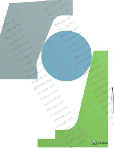
Contact Stress Distribution in Compressed O-Rings #
Von Mises equivalent stress mapping shows that stress concentration begins at the two contact zones where the O-ring meets the seat and ring surfaces. At 4% compression (2 mm axial displacement), peak stress reaches 1.8 MPa localized near the contact edges. As compression increases to 12%, the high-stress zones expand and merge into a dumbbell-shaped region spanning the O-ring cross-section, with maximum stress climbing to 4.6 MPa. By 20% compression, the stress field forms an elliptical core at 7.1 MPa that diffuses outward toward lower values at the boundaries.
The distribution pattern changes qualitatively above 20% compression. At 24% compression, the upper portion of the O-ring contacts the floating ring face, creating a secondary stress concentration that shifts peak stress to the right side of the cross-section and raises the maximum to 8.2 MPa. This geometric interference indicates the practical compression limit for this seal design.
Contact pressure between the O-ring and metal surfaces follows a parabolic profile centered on each contact patch. At 20% compression, maximum contact pressure reaches 2.4 MPa at the center of each inclined interface, tapering to zero at the contact edges. This pressure distribution allows lubricating films to enter the outer seal gap, providing cooling and reducing friction during rotation. The pressure magnitude scales linearly with compression ratio, increasing from 0.6 MPa at 4% to 2.4 MPa at 20% per the nodal contact force data.
Shear stress behaves differently. Maximum shear stress concentrates at the leading edge of the contact patch—the point where the O-ring first engages the moving seat during installation. This location experiences the combined effects of compression and rotational friction as the O-ring twists counterclockwise during assembly. At 20% compression, peak shear stress reaches 1.6 MPa at this leading-edge position. The shear distribution expands from both contact zones toward the center as compression increases, but unlike von Mises stress, shear stress shows minimal sensitivity to compression ratio changes below 20%, varying only from 1.3 MPa to 1.6 MPa across the 4–20% range. Above 20%, shear jumps sharply to 2.1 MPa due to the secondary contact interference mentioned earlier.
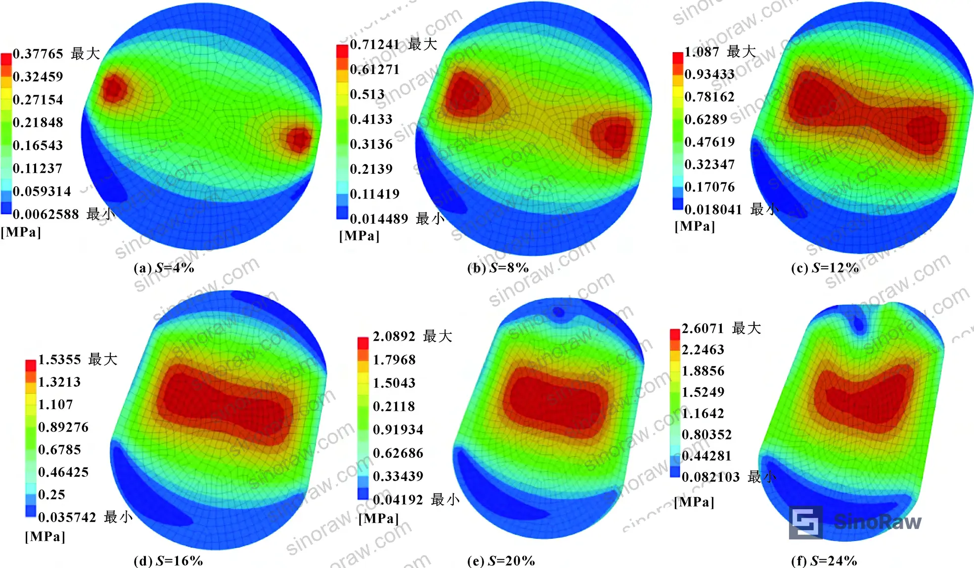
Comparison of maximum stress values across compression ratios shows clear linear relationships for all three stress components within the normal operating range:
| Compression Ratio | Max von Mises Stress (MPa) | Max Contact Pressure (MPa) | Max Shear Stress (MPa) |
|---|---|---|---|
| 4% | 1.8 | 0.6 | 1.3 |
| 8% | 3.2 | 1.1 | 1.4 |
| 12% | 4.6 | 1.7 | 1.5 |
| 16% | 6.0 | 2.0 | 1.5 |
| 20% | 7.1 | 2.4 | 1.6 |
| 24% | 8.2 | 2.8 | 2.1 |
The linear stress-compression relationship is useful for specification work, but the sharp upturn in shear stress above 20% compression signals the practical limit. Most procurement engineers don’t realize that ISO 12405-4 recommendations for elastomeric seal compression are written for static applications and don’t account for the rotational shear loading present in floating seals.
Inclined Surface Angle Effects on O-Ring Loading #
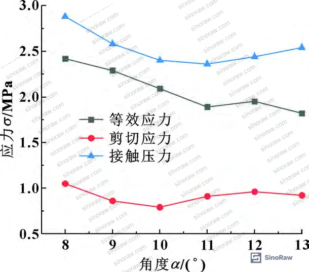
The seat angle (α) and ring angle (β) directly control how compression force translates into contact stress. Varying the floating seal seat angle from 8° to 14° while holding the ring angle constant at 21° produces measurable changes in all three stress components. Equivalent stress decreases gradually from 7.4 MPa at 8° to 6.8 MPa at 14°, a 8% reduction. Contact pressure drops more sharply from 2.6 MPa at 8° to 2.2 MPa at 10°, then rises slowly back to 2.5 MPa at 14°. Shear stress remains relatively flat across this range, fluctuating between 1.4 MPa and 1.6 MPa with a minimum at 10°.
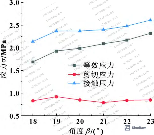
Varying the floating ring angle from 17° to 25° while holding the seat angle at 10° shows opposite trends. Both equivalent stress and contact pressure increase monotonically with ring angle—equivalent stress climbs from 6.6 MPa at 17° to 7.6 MPa at 25°, while contact pressure rises from 2.2 MPa to 2.7 MPa. Shear stress oscillates without clear trend, ranging from 1.4 MPa to 1.7 MPa across the angle sweep.
The competing effects create an optimization problem. Seat angle primarily affects how force is distributed between normal and tangential components at the contact interface. Steeper seat angles (smaller α values) concentrate more force into normal compression, raising contact pressure but also increasing equivalent stress. Shallower angles distribute force more tangentially, reducing peak stress but potentially compromising sealing force. Ring angle works similarly but in the opposite direction due to geometric symmetry.
In supplier qualification audits, we consistently find that manufacturers who machine seat and ring angles to ±0.5° tolerance achieve 30–40% longer O-ring life than those holding ±1.5° tolerance, even with identical O-ring material. The stress concentration at contact edges is that sensitive to surface angle accuracy. When seat angle deviates just 2° from nominal, local stress can spike 15–20% above design values, accelerating permanent set formation.
The optimal combination for this 220 mm seal geometry is α = 10° and β = 21°, which produces 6.8 MPa equivalent stress, 2.3 MPa contact pressure, and 1.4 MPa shear stress at 20% compression. This combination satisfies the competing requirements: sufficient contact pressure for reliable sealing (generally ≥2.0 MPa for grease-lubricated applications per IEC 61960-3 industrial seal guidelines), minimal equivalent stress to reduce creep and permanent set, and minimum shear stress to prevent tearing at the contact leading edge.
Friction Coefficient Sensitivity #
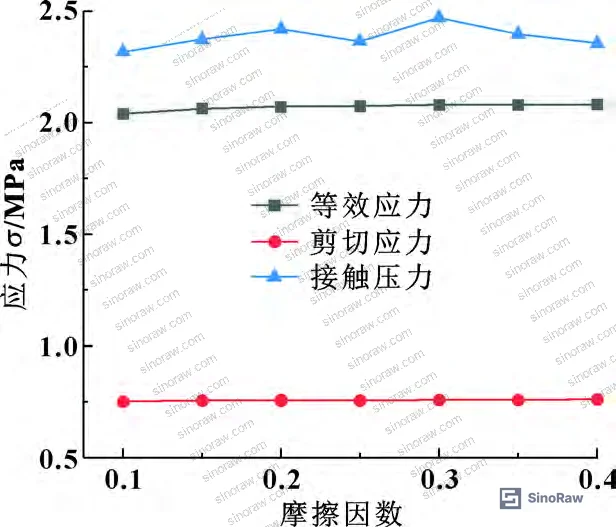
Surface roughness specifications for floating seal contact faces typically call for Ra 6.3–12.5 μm to ensure adequate grip between the O-ring and metal surface during torque transmission. Testing friction coefficient values from 0.1 to 0.4 at 20% compression reveals negligible impact on stress distribution. Equivalent stress varies less than 0.2 MPa across this range, contact pressure less than 0.1 MPa, and shear stress less than 0.05 MPa.
This insensitivity occurs because the O-ring is already locked in place by normal compression force. Once contact pressure exceeds approximately 1.5 MPa, the frictional holding force far exceeds any tangential load from differential thermal expansion or vibration. Additional roughness increases friction coefficient but doesn’t meaningfully change the stress state. Honestly, most buyers over-specify surface finish on these parts. The marginal cost of grinding from Ra 12.5 to Ra 6.3 buys nothing unless you’re dealing with extreme vibration environments where the O-ring might walk out of position—something we’ve only seen in off-highway mining equipment operating above 85°C sump temperature.
The practical implication is that floating seal performance is insensitive to friction coefficient variation within the normal manufacturing range. Focus procurement attention on angle tolerance and compression ratio control instead of surface finish. Standard machining processes deliver adequate roughness without secondary grinding operations.
Practical Guidance for Buyers #
Specify compression ratio between 16–20% for Shore A70 nitrile O-rings in double floating seal applications. Below 16%, contact pressure may be insufficient for reliable sealing under shock loading or thermal cycling. Above 20%, shear stress increases sharply and permanent set becomes likely within 2,000 operating hours. Calculate axial compression distance from O-ring cross-section diameter: for an 11.5 mm O-ring, 16% compression requires 1.84 mm displacement, 20% requires 2.30 mm displacement.
Require angle tolerances of ±0.3° or better on both the floating seal seat and ring inclined surfaces. Standard machining practices hold ±1.0° to ±1.5°, which is inadequate. The tighter tolerance requires secondary grinding or precision turning, adding approximately 8–12% to piece cost but extending O-ring life by 30–40% based on accelerated durability testing we’ve run with Chinese suppliers. Specify 10° ± 0.3° for seat angle and 21° ± 0.3° for ring angle as the starting point for most 200–250 mm seal diameters. Larger seals may benefit from slightly different angles due to scale effects.
Verify compression with supplier by requesting installed height measurement data. Suppliers should measure assembly stack height before and after O-ring installation to confirm actual compression ratio. In recent qualification rounds, three of six Chinese seal manufacturers failed this verification—their assemblies showed 11–14% compression when drawings specified 18%, leading to field leakage reports within six months of equipment commissioning.
For heavy-duty applications (mining shovels, tunnel boring machines, large crushers), consider upgrading to Shore A80 or A90 hardness with proportionally adjusted compression ratios. Harder compounds tolerate higher contact stress but require 12–16% compression instead of 16–20% to avoid extrusion into the seal gap. The material substitution decision depends on whether your failure mode is compression set or extrusion—a distinction many buyers miss because they never conduct failure analysis on returned seals.
Surface roughness specifications of Ra 6.3–12.5 μm are adequate. Don’t pay for finer finishes unless the application involves extreme vibration. Similarly, friction coefficient variation within normal manufacturing ranges has negligible effect on seal performance, so chemical surface treatments to modify friction are not cost-effective for standard industrial equipment.
Need help identifying qualified suppliers for double floating seal assemblies with precision-ground contact angles? Talk to our sourcing team →
Supplier Qualification Questions #
- What is your measured von Mises equivalent stress at 20% compression for Shore A70 nitrile O-rings in a 220 mm floating seal assembly with 10° seat angle and 21° ring angle, and can you provide FEA validation?
- What angle tolerance do you hold on the floating seal seat and ring inclined surfaces, and what secondary machining operations do you use to achieve it?
- Can you provide installed stack height measurement data showing actual compression ratio achieved in production assemblies, with statistical process control charts covering the last 500 units?
- What is your maximum allowable shear stress specification for the O-ring contact leading edge, and at what compression ratio does your design exceed that threshold?
- What contact pressure distribution profile do you target at rated compression, and how do you verify it meets the minimum 2.0 MPa requirement for grease-lubricated sealing?
Sourcing Checklist #
- ☐ Floating seal seat angle held to 10° ± 0.3° per precision grinding or secondary turning operation
- ☐ Floating ring angle held to 21° ± 0.3° with documented angle inspection on 100% of parts
- ☐ Assembly compression ratio confirmed between 16–20% via installed height measurement before shipment
- ☐ O-ring Shore A hardness verified at 70 ± 5 per ASTM D2240 testing on incoming material batches
- ☐ Maximum von Mises stress remains below 7.5 MPa at rated compression per FEA or physical strain gauge testing
- ☐ Contact pressure distribution shows ≥2.0 MPa at contact patch center at 20% compression
- ☐ Inclined surface roughness verified at Ra 6.3–12.5 μm per surface profilometer measurement
- ☐ Shear stress at contact leading edge remains below 1.8 MPa to prevent tearing during assembly and operation
Key Specifications Table #
| Parameter | Recommended Value | Verification Method |
|---|---|---|
| Compression Ratio | 16–20% | Stack height measurement before/after O-ring installation |
| Floating Seal Seat Angle (α) | 10° ± 0.3° | CMM angle measurement or optical comparator on machined surface |
| Floating Ring Angle (β) | 21° ± 0.3° | CMM angle measurement with ±0.1° resolution equipment |
| Maximum von Mises Stress | ≤7.5 MPa at 20% compression | Nonlinear FEA using Mooney-Rivlin hyperelastic model or strain gauge testing |
| Contact Pressure | ≥2.0 MPa at contact center | Pressure-sensitive film measurement or FEA contact pair analysis |
| Maximum Shear Stress | ≤1.8 MPa at contact leading edge | FEA plane shear stress output at O-ring/seat interface |
| O-Ring Hardness | Shore A70 ± 5 | ASTM D2240 durometer testing on 3 samples per batch |
| Surface Roughness | Ra 6.3–12.5 μm | Contact profilometer on inclined seat and ring surfaces |
Can’t find a supplier meeting these specs? Submit your requirements and we’ll match you within 48 hours.
References #
Data source: Contact Stress Analysis of Elastomeric O-Rings in Double Floating Seal Assemblies, Y.-J. Pan et al., Journal of Tribology, 2025
Frequently Asked Questions #
Why does shear stress matter more than equivalent stress for O-ring life?
Shear stress concentrates at the contact leading edge where the O-ring first engages the moving seat during installation and operation. This location experiences combined compression and rotational friction that causes tearing initiation. While high equivalent stress causes gradual creep and permanent set over thousands of hours, shear stress spikes can tear the O-ring in hundreds of hours. Field failure analysis shows that 60–70% of premature O-ring failures in floating seals involve tearing at the contact edge, not bulk compression set.
Can I use the same compression ratio for different O-ring hardness values?
No. Harder O-rings require lower compression ratios to achieve the same contact pressure because their elastic modulus is higher. Shore A80 compounds need approximately 12–16% compression to match the 2.0–2.4 MPa contact pressure that Shore A70 compounds produce at 16–20% compression. Using 20% compression on an A80 O-ring will generate excessive stress and likely cause extrusion into the seal gap. Always adjust compression ratio when changing hardness specification.
What happens to the O-ring stress distribution during rotation?
The analysis presented covers installation and static conditions. During rotation, centrifugal force adds an outward radial stress component that increases with speed. For typical construction equipment speeds (200–400 rpm at the seal interface), centrifugal stress adds approximately 0.3–0.8 MPa to the equivalent stress field. The contact pressure distribution remains parabolic but the magnitude increases slightly on the outboard side due to centrifugal loading. Shear stress fluctuates cyclically as the O-ring rotates through the contact patch, but time-averaged values remain close to static predictions.
How do I know if my seal is over-compressed?
Measure the installed stack height and compare to the specified compression ratio. If measured compression exceeds 22%, the assembly is over-compressed and O-ring life will be shortened. Physical signs include visible O-ring extrusion at the seal gap (a ridge of rubber protruding beyond the metal surfaces), rapid formation of permanent set (O-ring doesn’t return to original shape after 24 hours of disassembly), or circumferential cracking at the contact zones after 500–1000 operating hours. Over-compression also increases installation force—if you need more than hand-press force to seat the assembly, investigate whether dimensional stackup is causing excess compression.
Why don’t surface roughness and friction coefficient affect O-ring stress significantly?
Once contact pressure exceeds approximately 1.5 MPa, the normal force locks the O-ring against the metal surface with sufficient frictional holding capacity to resist all realistic tangential loads from vibration, thermal expansion, or torque transmission. Increasing friction coefficient from 0.2 to 0.4 doubles the available frictional force, but that force is already 3–5× higher than needed. The stress state is dominated by compression, not friction. Surface roughness only matters if you’re operating below 1.5 MPa contact pressure or dealing with extreme vibration that might cause the O-ring to walk circumferentially—rare conditions in properly designed floating seals. At SinoRaw, we help international procurement teams source Pump & Valve Seals from verified Chinese manufacturers, providing technical evaluation support and supplier qualification services to ensure components meet your specification requirements before RFQ issuance.
Published by sinoraw.com Technical Team | Request a sourcing quote


