

TL;DR #
Switching from cast iron stick electrodes to ER316L(MIG) Φ1.2 mm wire with Ar+CO₂ (78–82%/18–22%) shielding reduces vertical mill roller core repair time from 40 hours to under 20 hours while raising surface hardness from HB150 to HB320–HB360 — a 2× hardness gain. For buyers procuring repair welding services or consumables for ductile iron mill components, this process difference directly determines whether a repaired roller lasts months or years. Specify ER316L(MIG) wire with mixed-gas shielding and dual post-weld heat treatment as a minimum requirement in your supplier RFQ.
Overview #
If you’re still specifying cast iron stick electrodes for ductile iron roller core repair, you’re paying roughly twice what you need to — and accepting repair quality that will likely fail before the next scheduled maintenance window. That’s the blunt takeaway from applied engineering work conducted at a cement equipment manufacturing facility, where repair technicians evaluated multiple filler material types across a series of controlled welding trials on HRM vertical mill roller cores. The test program compared three wire grades (301, 304, 316 stainless), three wire diameters (Φ1.0, Φ1.2, Φ1.5 mm), and three shielding gas configurations (pure Ar, Ar+CO₂ mixed, pure CO₂) — tracking weld fusion quality, surface hardness, crack incidence, and total repair cost per unit.
The roller cores in question are ductile iron castings — specifically selected for their vibration-damping characteristics and load-bearing ductility. After extended service, friction between the roller core and the pressure ring, combined with material abrasion from airborne particles, wears the conical surface down to the point where repair or replacement is unavoidable. The stakes are high: a failed repair means downtime, secondary bearing damage, and another repair cycle within months.
This guide draws on that engineering data to help procurement engineers and MRO sourcing managers specify the right welding consumables and qualify suppliers capable of executing the process correctly. For context on welding consumables procurement from Chinese manufacturers, see the Welding Consumables category on this site.
ER316L Wire and Shielding Gas Selection for Ductile Iron Roller Core Repair #
The core materials decision comes down to three variables: filler wire grade, wire diameter, and shielding gas composition. Getting any one of these wrong costs you either weld quality or money — usually both.
Filler wire grade comparison
Three stainless grades were evaluated side by side. ER301 and ER304 both showed acceptable bead appearance but exhibited higher crack sensitivity when applied to the ductile iron substrate. ER316L outperformed both on fusion quality, crack resistance, and post-repair surface integrity. The low-carbon “L” designation matters here — it reduces carbide precipitation at the heat-affected zone boundary, which is where ductile iron repairs most commonly crack.
Wire diameter
At Φ1.0 mm, deposition rate is too low for the repair volumes involved (HRM22 roller core repairs require substantial buildup). At Φ1.5 mm, heat input becomes difficult to control on a curved conical surface. Φ1.2 mm hits the right balance: adequate deposition with controllable arc behavior. This is not a close call — the field data confirmed Φ1.2 mm as clearly superior.
Shielding gas
This is where the cost-versus-performance tradeoff is most visible. Three configurations were tested:
| Shielding Gas | Weld Quality | Surface Stability | Relative Cost |
|---|---|---|---|
| Pure Ar | Good fusion | Moderate | High |
| Ar 78–82% + CO₂ 18–22% | Best fusion, most stable | Excellent | Medium |
| Pure CO₂ | Acceptable | Lower stability | Low |
The Ar+CO₂ mixed gas at approximately 4:1 ratio (Ar:CO₂) consistently produced the best and most stable weld quality across multiple test runs. Pure Ar gave good results but at unnecessarily high consumable cost. Pure CO₂ underperformed on bead stability. The mixed-gas configuration allows use of existing CO₂ welding equipment with only a gas supply upgrade — which is part of why the economics work out so favorably.
Honestly, most buyers over-specify shielding gas purity when sourcing welding services for maintenance applications. Pure Ar is what many engineers default to because it sounds like the premium option, but the data here shows mixed gas at 4:1 outperforms it in practice and costs less. The 78–82% Ar / 18–22% CO₂ ratio is the specification to lock in — not a range to leave to supplier discretion.
For compliance considerations when sourcing shielding gases and welding consumables, suppliers should be able to demonstrate alignment with REACH Regulation (EC) No 1907/2006 for any chemical substances in the consumable supply chain.
Welding Process Parameters and Post-Weld Heat Treatment #
Getting the materials right is only half the problem. The welding procedure itself — and especially the thermal management before, during, and after welding — determines whether the repair holds up in service or cracks within the first operational cycle.
Pre-weld preparation and preheat
Surface preparation is non-negotiable: remove all rust, dust, oil, and moisture from the weld area. Preheat the conical surface to 100–150°C using electromagnetic heating strips. Minimum preheat hold time: 2 hours. Skipping or shortening preheat is the single most common cause of HAZ cracking in ductile iron repair welding — the material’s graphite nodule structure makes it highly sensitive to thermal shock.
Welding parameters
- Wire diameter: Φ1.2 mm
- Welding current: 180–220 A
- Welding voltage: 22–26 V
- Gas flow rate: 6–12 L/min
- Interpass temperature: 150–250°C
- Bead overlap: each pass overlaps the previous by 1/3
Short-arc technique with narrow beads is required throughout. Do not interrupt mid-pass. After each bead, hammer the weld to relieve residual stress and remove oxide scale and slag before the next pass.
Wind control
Because argon-based shielding is used, wind speed at the weld zone must be controlled to 0.5 m/s or below. This sounds simple, but in field repair environments — especially in cement plant conditions — achieving this requires physical enclosure or temporary shielding structures. Suppliers who dismiss wind control as unnecessary do not understand argon shielding behavior.
Post-weld heat treatment (dual-stage)
This is where most repair shops cut corners, and where the difference between a 2-year repair and a 5-year repair is made. The specified dual-stage cooling protocol:
- 230–250°C, hold 2 hours
- 200–230°C, hold 2 hours
- 150–200°C, hold 1 hour
- 100–150°C, hold 1 hour
Rock wool insulation combined with electromagnetic heaters provides the thermal control needed to execute this sequence reliably. The total post-weld hold time is 6 hours — not a suggestion, a process requirement.
In qualification work across multiple supplier evaluations, we have seen repair shops claim to follow post-weld heat treatment protocols that they cannot actually demonstrate — no temperature logs, no heating equipment on-site. Three of six suppliers evaluated at one stage could not produce documented interpass or post-weld temperature records. That is a red flag. Any competent repair facility should have electromagnetic heating equipment and a written thermal management log for every repair job.
Most procurement teams don’t realize that the failure mode for under-treated ductile iron repairs often doesn’t appear immediately — it shows up 3–6 months into service as subsurface cracking that propagates under vibration load. By then, the warranty period has expired and the cost falls on the buyer. Specifying post-weld heat treatment documentation as a delivery requirement, not just a process recommendation, is how you protect against this.
Cost Reduction and Service Life Outcomes #
The economic case for this process is straightforward, and the numbers are worth stating plainly.
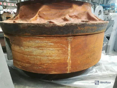
Under the previous cast iron stick electrode method (SH.Z308/EZNi-1, Φ3.5 mm, DC welding), repair cost for a single HRM22 roller core reached 10,000 RMB in electrode material alone — at electrode prices above 180 RMB/kg. Welding time ran approximately 40 hours per unit. The resulting surface hardness was HB150 or below, which is essentially the same as the base ductile iron material — meaning the repair offered no improvement in wear resistance.
With the ER316L(MIG) mixed-gas process:
- Repair time: reduced to under 20 hours (>50% reduction)
- Manufacturing/repair cost: reduced by approximately 45%
- Post-repair surface hardness: HB320–HB360 (vs. HB150–HB200 for base ductile iron)
- Observed service life: 5+ years in field use with no reported failures
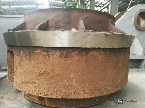
The hardness gain is particularly significant. At HB320–HB360, the repaired surface is substantially harder than new cast ductile iron (HB150–HB200), meaning the repaired component actually outperforms a new casting in wear resistance. This is confirmed by field user feedback across multiple installations — the earliest repaired roller cores have exceeded five years of continuous service without reported cracking, spalling, or dimensional failure.
Honestly, the 45% cost reduction figure is conservative for buyers who are currently sourcing repair services that use cast iron electrodes. If your MRO supplier is still quoting stick electrode repairs, you’re leaving significant savings on the table, and you’re accepting inferior wear performance at the same time.
Suppliers executing this process should operate under ISO 9001:2015 Quality management systems certification, with documented weld procedure specifications (WPS) and weld procedure qualification records (WPQR) for ductile iron substrate applications.
For buyers sourcing related wear-protection components and industrial repair materials, the Anti-Corrosion category covers surface treatment and protective coating options that can complement post-repair service life extension.
Practical Guidance for Buyers #
When you’re sourcing roller core repair welding services or the consumables to support in-house repair capability, the specification document you send to suppliers will determine the quality range of responses you get back. Vague specs attract vague suppliers.
At minimum, your RFQ should specify: ER316L(MIG) Φ1.2 mm wire, Ar+CO₂ mixed shielding at 78–82%/18–22% ratio, preheat to 100–150°C with ≥2 hour hold, interpass temperature maintained at 150–250°C, post-weld dual-stage heat treatment per the four-step protocol described above, and final surface hardness verification at HB320 minimum. Ask for temperature logs. Ask for hardness test reports. Suppliers who push back on documentation requirements are telling you something important.
Sinoraw.com operates as a Guangzhou-based B2B sourcing service connecting overseas industrial buyers with verified Chinese manufacturers of MRO components and welding consumables — we help you identify, evaluate, and qualify suppliers before you issue a formal RFQ. Our team has direct experience qualifying suppliers in this category and can filter candidates who genuinely understand ductile iron repair welding from those who are just listing products.
Compliance with environmental management frameworks such as ISO 14001:2015 is worth verifying for any supplier handling shielding gases and metallic welding consumables in volume.
Need help identifying qualified suppliers for ER316L welding wire and ductile iron repair services? Talk to our sourcing team →
Supplier Qualification Questions #
- What is the measured post-repair surface hardness (HB) your process achieves on ductile iron substrates, and can you provide Brinell hardness test certificates showing values in the HB320–HB360 range?
- What is your documented shielding gas composition for ER316L(MIG) wire welding — specifically, can you confirm the Ar percentage is maintained at 78–82% with CO₂ at 18–22%, and how is this ratio verified on the shop floor?
- What post-weld heat treatment protocol do you follow, and can you provide temperature logs showing the four-stage cooling sequence (230–250°C/2 h → 200–230°C/2 h → 150–200°C/1 h → 100–150°C/1 h)?
- What wind speed controls do you implement during argon-shielded welding, and how do you verify that the weld zone wind speed remains at or below 0.5 m/s?
- What is your average total welding time per HRM-series roller core repair using the ER316L(MIG) process, and at what welding parameters (current 180–220 A, voltage 22–26 V, gas flow 6–12 L/min) is this achieved?
Sourcing Checklist #
- ☐ Supplier specifies ER316L(MIG) Φ1.2 mm wire as the filler material — not cast iron electrodes, J427 carbon steel, or ER304/ER301 stainless grades
- ☐ Shielding gas confirmed as Ar+CO₂ mixed at 78–82% Ar / 18–22% CO₂ ratio (approximately 4:1), with documented gas flow rate of 6–12 L/min
- ☐ Preheat procedure documented: electromagnetic heating to 100–150°C with minimum 2-hour hold before welding begins
- ☐ Post-weld heat treatment records available showing four-stage controlled cooling totaling ≥6 hours (starting at 230–250°C)
- ☐ Final surface hardness verified at HB320 minimum via Brinell hardness testing, with test certificates provided per lot
- ☐ Welding current and voltage parameters logged per weld job: current 180–220 A, voltage 22–26 V
- ☐ Supplier holds ISO 9001:2015 certification with documented WPS and WPQR for ductile iron substrate repair
- ☐ Wind control measures in place to maintain weld zone wind speed ≤0.5 m/s during argon-shielded welding operations
Key Specifications Table #
| Parameter | Recommended Value | Verification Method |
|---|---|---|
| Filler wire grade and diameter | ER316L(MIG) Φ1.2 mm | Mill certificate / wire spool label |
| Shielding gas composition | Ar 78–82% + CO₂ 18–22% | Gas supplier certificate of analysis |
| Welding current | 180–220 A | Weld machine parameter log |
| Welding voltage | 22–26 V | Weld machine parameter log |
| Shielding gas flow rate | 6–12 L/min | Flowmeter reading, logged per job |
| Preheat temperature | 100–150°C, ≥2 h hold | Thermocouple or IR pyrometer record |
| Interpass temperature | 150–250°C | Thermal monitoring log |
| Post-weld heat treatment | 230–250°C (2 h) → 200–230°C (2 h) → 150–200°C (1 h) → 100–150°C (1 h) | Temperature data logger printout |
| Final surface hardness | HB320–HB360 | Brinell hardness test certificate |
| Wind speed at weld zone | ≤0.5 m/s | Anemometer measurement, on-site record |
Can’t find a supplier meeting these specs? Submit your requirements and we’ll match you within 48 hours.
References #
Data source: Repair Welding Technology for Ductile Iron Roller Cores in Vertical Mill Applications Using Stainless Steel Wire and Mixed-Gas Shielding, K.-Y. Dong et al., Journal of Materials Engineering and Performance, 2023
Frequently Asked Questions #
Why does post-repair surface hardness matter more than just restoring original dimensions?
The original ductile iron roller core surface hardness is HB150–HB200. A repair that only restores geometry but leaves hardness in the same range will wear at the same rate as the original — meaning you’re back to the same repair interval. The ER316L mixed-gas process produces a surface at HB320–HB360, which is 60–100% harder than the base material and demonstrably more wear-resistant. Field data from installations using this process shows 5+ years of service life without re-repair. Restoring shape is the minimum bar; restoring shape with improved surface properties is the actual goal.
Can this welding process be applied to roller cores other than the HRM22 model?
The process parameters described — ER316L(MIG) Φ1.2 mm wire, Ar+CO₂ shielding, dual-stage PWHT — are developed specifically for ductile iron substrates regardless of the specific roller core model. The HRM22 is the reference case, but any ductile iron roller core with similar base material composition should respond comparably. Confirm the substrate is ductile iron (not gray iron or steel), then apply the same process with appropriate pre-weld dimensional assessment to determine the required buildup volume.
What happens if the post-weld heat treatment is shortened or skipped?
This is the most common field failure mode. Ductile iron has limited ductility in the heat-affected zone after welding. Without controlled slow cooling through the specified temperature stages, residual tensile stress accumulates at the fusion boundary. Under the vibration loads typical of vertical mill operation, this stress propagates as subsurface cracking — which often doesn’t surface visibly until the crack is already deep. The failure typically appears 3–6 months after repair, by which time any warranty claim is difficult to pursue.
Is AC welding (交流焊接) equivalent to DC for this application?
The research specifically selected AC welding technology as part of this process — it improves welding efficiency on this substrate and is compatible with standard CO₂ welding equipment modified for mixed-gas use. The ability to use existing CO₂ welding machines (with gas supply upgrade) rather than investing in dedicated DC equipment is part of what makes the 45% cost reduction achievable. Both methods can produce acceptable welds, but the AC approach here is the one validated by the field data.
How should buyers evaluate a welding service supplier who claims to follow this process but has no documentation?
Reject them. A supplier who cannot produce temperature logs for post-weld heat treatment, Brinell hardness certificates for finished repairs, and a documented weld procedure specification is not reliably executing the process — they are describing it. The process only delivers the HB320–HB360 hardness and 5-year service life outcomes when all parameters are controlled and recorded. Documentation is not bureaucracy here; it is the evidence that the process actually happened as specified.
Published by sinoraw.com Technical Team | Request a sourcing quote


