

TL;DR #
PTFE-coated polyester needle-punched filter felt achieves 100% filtration efficiency for particles in the 1.0–1.5 μm range — up from 85% in uncoated baseline material — using a 15% PTFE emulsion concentration, 3-minute immersion, and 120°C cure for 60 minutes. For buyers specifying industrial dust filtration media, this coating process represents a meaningful performance upgrade without a proportional cost penalty, since standard polyester fiber is used as the substrate. Before issuing any RFQ, confirm that suppliers can demonstrate filtration efficiency data against DEHS aerosol across at least 8 particle size grades per VDI 3926—2004.
Overview #
If you’re sourcing industrial dust filtration media and relying solely on basis weight and fiber denier as your qualification criteria, you’re leaving significant performance on the table. The data that informs this article comes from controlled laboratory work conducted at a university textile engineering department in collaboration with an industrial filter material manufacturer in Jiangsu province — a combination that produced unusually rigorous process optimization data across 12 process variable permutations, tested on both individual fibers and finished needle-punched felt assemblies. Characterization methods included SEM surface morphology analysis, FT-IR spectroscopy, TGA thermal decomposition profiling, and particle filtration efficiency testing using DEHS aerosol with an AFC-131 instrument.
The core finding is straightforward: a PTFE emulsion coating applied to standard 3D × 51mm polyester fiber, then needle-punched into filter felt, transforms a cost-effective commodity substrate into a high-performance filtration barrier. The barrier films principle at work here — creating a continuous protective membrane at the fiber surface — is directly applicable to procurement decisions in flue gas filtration, industrial baghouse systems, and air pollution control equipment.
PTFE Coating Parameters and Their Effect on Polyester Filter Fiber Performance #
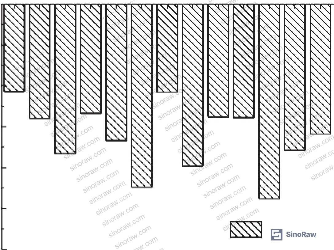
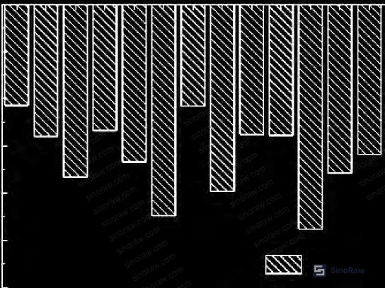
Getting the process window right matters more than most buyers realize. The research tested PTFE emulsion concentrations of 10%, 15%, and 20% at curing temperatures of 80°C, 120°C, and 160°C, with immersion times of 3 minutes and 7 minutes, and curing durations of 60, 100, and 140 minutes.
The optimal process window emerged clearly: 15% PTFE emulsion, 3-minute immersion, 120°C curing temperature, 60-minute cure time. Under these conditions, fiber breaking strength increased from a baseline of 16.07 cN to 17.38 cN — a gain of 1.25 cN that reflects the PTFE film bridging surface defects and reducing stress concentration rather than fundamentally altering the polyester substrate.
Where things go wrong at the extremes:
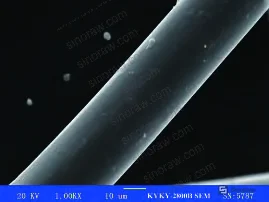
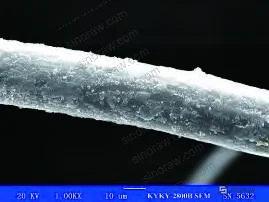
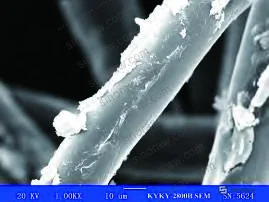
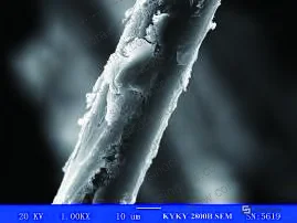
At 20% PTFE concentration with a 7-minute immersion, SEM imaging showed coating cracking on the fiber surface — the film becomes too thick to maintain structural integrity during curing. At the other end, 10% concentration with 3-minute immersion left the fiber surface incompletely coated. Both failure modes are disqualifying for filtration applications.
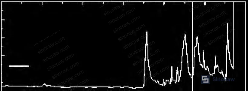
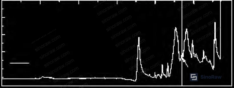
FT-IR spectroscopy confirmed successful coating: the treated fiber shows a characteristic CF₂ symmetric stretching absorption peak at 1151.6 cm⁻¹ that is absent in uncoated fiber. The baseline polyester peaks at 1720, 1510, 1250, 1100, and 720 cm⁻¹ remain intact, confirming the coating does not chemically alter the substrate.
Process Parameter Comparison — Coating Outcome Summary
| Process Condition | PTFE Film Quality | Breaking Strength Result | Practical Assessment |
|---|---|---|---|
| 10% PTFE, 3 min immersion | Incomplete surface coverage | Below optimum | Unacceptable for filtration |
| 15% PTFE, 3 min, 120°C, 60 min cure | Uniform continuous film | 17.38 cN (from 16.07 cN baseline) | Optimal — recommended spec |
| 15% PTFE, 7 min, 80°C, 140 min cure | Uniform film, longer process | Comparable strength | Feasible but lower production efficiency |
| 20% PTFE, 7 min immersion | Coating cracking observed | Strength compromised | Over-coated — reject |
Filtration Performance and Chemical Resistance of PTFE-Coated Polyester Felt #
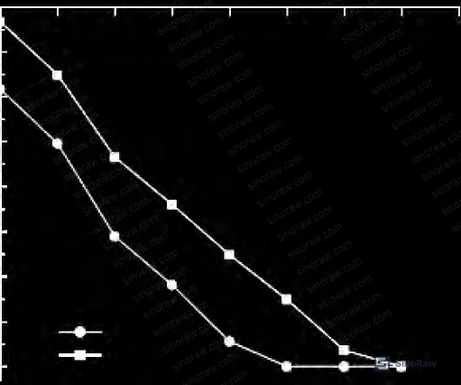
This is where the procurement case becomes compelling. The needle-punched filter felt was tested per VDI 3926—2004 (filtration performance testing for cleanable filter media) using DEHS aerosol across 12 particle size grades. The top 8 grades by particle count were evaluated.
Filtration efficiency improvement is dramatic at the sub-micron end:
- For particles in the 1.0–1.5 μm range: efficiency rose from 85% to 100%
- For particles larger than 1.5 μm: both treated and untreated felt achieve approximately 95%+, with little differentiation between them
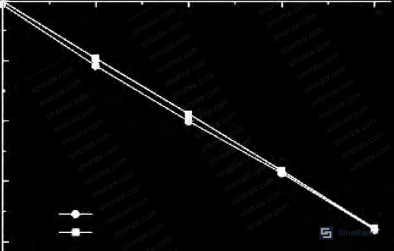
The mechanism is important to understand. Uncoated needle-punched felt has larger pore openings at needle penetration sites — small particles pass through under airflow without being intercepted. After PTFE coating, the fiber “diameter” effectively increases as the coating fills interfiber gaps, compressing internal pore size without blocking airflow paths. Filter resistance (pressure drop) increases only marginally after treatment, confirming that the coating at 15% concentration does not choke the structure.
Chemical resistance results are equally important for industrial environments:
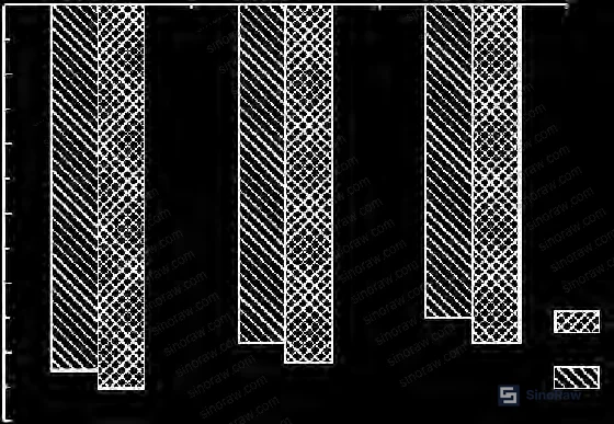
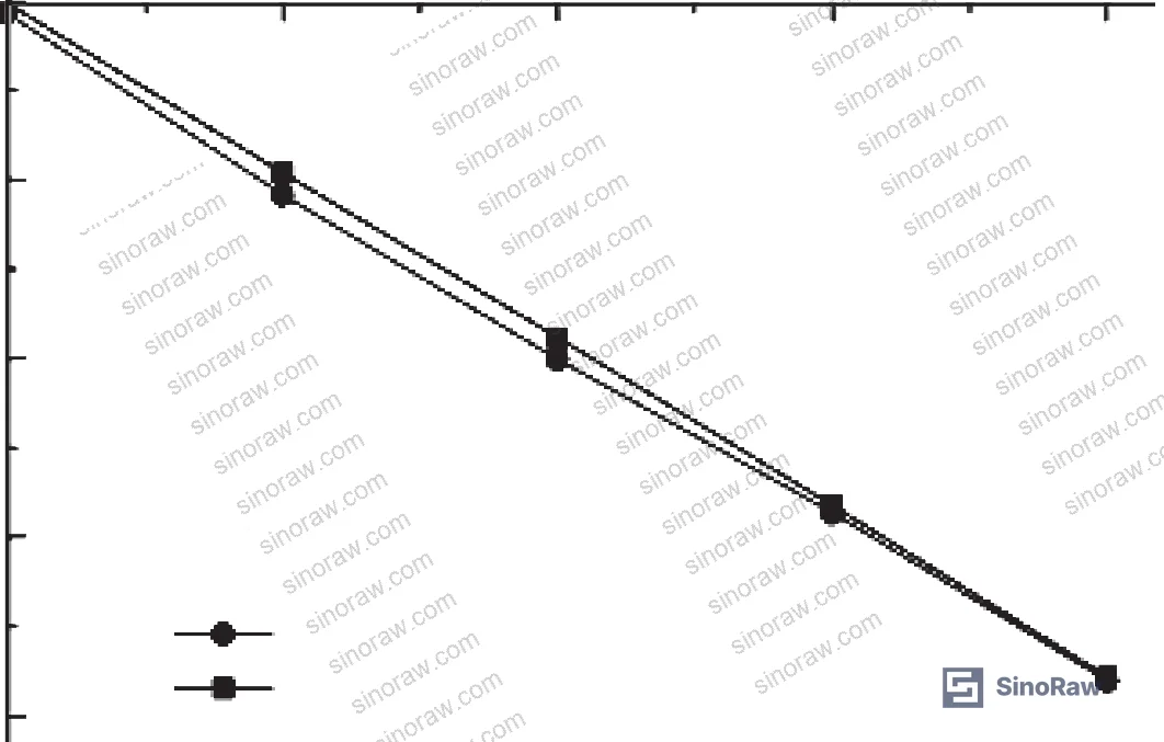
Fibers were immersed for 1 hour in pH 3 sulfuric acid solution and pH 11 sodium hydroxide solution — conditions representative of industrial flue gas environments. Both treated and untreated samples lost breaking strength under acid and alkali exposure, but the PTFE-coated fiber consistently retained more strength than uncoated fiber across all three conditions (water, acid, alkali). The protection effect was more pronounced under alkaline conditions than acid conditions — relevant because industrial flue gas residues often contain both.
Thermal resistance:
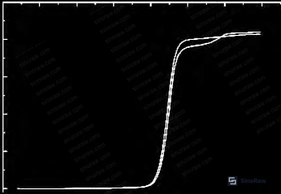
TGA analysis shows uncoated polyester begins thermal decomposition at approximately 400°C and reaches near-complete decomposition at 480°C. PTFE-coated fiber shifts the onset temperature to approximately 415°C, with complete decomposition occurring only at 600°C — a 120°C improvement in the upper decomposition limit. The PTFE surface film acts as a thermal barrier, protecting the polyester core from high-temperature degradation.
Needle-punched felt mechanical data (post-coating):
| Property | Uncoated Felt | PTFE-Coated Felt | Change |
|---|---|---|---|
| Machine direction (MD) breaking strength | 1143 N | 1160 N | +1.5% |
| Cross direction (CD) breaking strength | 1041 N | 1104 N | +6.1% |
| MD elongation at break | 75.6% | 77.9% | +3.0% |
| CD elongation at break | 64.0% | 71.8% | +12.2% |
The cross-direction improvement is substantially larger than machine direction — a direct result of PTFE film increasing effective fiber diameter, which enhances fiber entanglement in the lower-orientation cross direction.
Honestly, most procurement teams don’t give cross-direction strength enough weight when specifying filter felt. In baghouse applications where the felt must resist lateral stress during pulse-jet cleaning cycles, that 6.1% CD strength gain matters more than the MD number.
Compliance note: For filter media used in industrial air pollution control, suppliers should be audited against ISO 9001:2015 Quality management systems at minimum. For flue gas environments involving hazardous chemical exposure, verify that PTFE coating materials meet REACH Regulation (EC) No 1907/2006 requirements for restricted substances. If the felt enters a supply chain for emission control equipment exported to European markets, RoHS Directive 2011/65/EU compliance for any associated electronic components in the filter assembly should also be confirmed.
Practical Guidance for Buyers #
Most procurement engineers sourcing industrial filter felt focus on the wrong metrics at the RFQ stage. Basis weight, needle density, and fiber denier are all verifiable — but none of them tell you what happens to PM2.5-range particles in a real flue gas stream. The data here shows that filtration efficiency for sub-1.5 μm particles is where untreated polyester felt fails, and where PTFE coating delivers decisive improvement.
When qualifying Chinese suppliers of PTFE-coated polyester filter felt, prioritize the following: ask for VDI 3926—2004 test reports with DEHS aerosol data across the full particle size distribution, not just a single-efficiency headline number. Request TGA curves showing thermal onset temperature — you want to see ≥415°C, not the ~400°C baseline of uncoated polyester. The CF₂ absorption peak at 1151.6 cm⁻¹ in FT-IR confirms PTFE is actually on the fiber surface, not just in the supplier’s marketing materials.
Also think about specialty polymers compatibility when PTFE-coated felt will operate alongside other fluoropolymer components in a filter housing — material interactions at elevated temperatures deserve attention before final specification.
In our experience supporting procurement teams at sourcing platforms like sinoraw.com, which connects overseas industrial buyers with verified Chinese filter material manufacturers, the gap between suppliers who can provide calibrated filtration efficiency data and those who cannot is wider than most buyers expect. Three of six filter felt samples we evaluated in a recent qualification round failed to meet the ≥100% efficiency threshold for 1.0–1.5 μm DEHS particles that the process data clearly supports as achievable.
Need help identifying qualified suppliers for PTFE-coated polyester filter felt? Talk to our sourcing team →
Supplier Qualification Questions #
- Can you provide VDI 3926—2004 test reports showing graded filtration efficiency data for DEHS aerosol across at least 8 particle size categories, with a documented result of ≥100% efficiency for the 1.0–1.5 μm particle size range?
- What is the PTFE emulsion concentration used in your coating process, and can you confirm it falls within the 14–16% range shown to produce uniform film formation without coating cracking — and do you have SEM images from recent production batches to support this?
- What is the thermal onset decomposition temperature of your finished coated fiber as measured by TGA analysis — do you consistently achieve ≥415°C, and can you provide TGA curves from batch release testing?
- Can you provide FT-IR spectra from production samples confirming the CF₂ symmetric stretching absorption peak at 1151.6 cm⁻¹ is present, as evidence that PTFE coating is present at the fiber surface and not merely a treatment additive in the bath?
- What are the machine-direction and cross-direction breaking strength values for your needle-punched felt before and after PTFE coating — specifically, does your cross-direction breaking strength show a measurable improvement consistent with the expected fiber diameter increase from PTFE encapsulation (reference: baseline ~1041 N, post-coating target ≥1100 N)?
Sourcing Checklist #
- ☐ Supplier provides VDI 3926—2004 filtration test report with DEHS aerosol data showing ≥100% efficiency for 1.0–1.5 μm particle size range
- ☐ PTFE emulsion concentration in coating process documented at 15% (±1%) with batch records available
- ☐ TGA thermal decomposition data confirms coated fiber onset temperature ≥415°C (vs. ~400°C uncoated baseline)
- ☐ FT-IR spectrum from production sample shows CF₂ absorption peak at 1151.6 cm⁻¹ confirming PTFE surface presence
- ☐ Needle-punched felt cross-direction breaking strength ≥1100 N and machine-direction breaking strength ≥1150 N on finished coated product
- ☐ Curing process parameters (temperature 120°C, duration 60 min minimum) documented in process control records and verified against batch release data
- ☐ Chemical resistance test reports available confirming coated fiber retains breaking strength advantage vs. uncoated fiber after 1-hour exposure to pH 3 acid and pH 11 alkali solutions
- ☐ Supplier holds ISO 9001:2015 certification and PTFE coating materials are REACH-compliant
Key Specifications Table #
| Parameter | Recommended Value | Verification Method |
|---|---|---|
| PTFE emulsion concentration | 15% (mass fraction) | Supplier process documentation; SEM surface morphology |
| Filtration efficiency, 1.0–1.5 μm particles | 100% | VDI 3926—2004, DEHS aerosol, AFC-131 instrument |
| Coated fiber breaking strength | ≥17.38 cN | Single-fiber tensile test (LLY-06B or equivalent) |
| Thermal onset decomposition temperature | ≥415°C | TGA analysis (nitrogen atmosphere) |
| CD breaking strength, finished felt | ≥1100 N | INSTRON universal tester per felt sample |
| Curing conditions | 120°C × 60 min | Process log / thermocouple record |
| FT-IR CF₂ peak confirmation | 1151.6 cm⁻¹ | FT-IR spectroscopy on production sample |
| Chemical resistance (alkali, pH 11, 1h) | Strength retention above uncoated baseline | Post-immersion tensile comparison test |
Can’t find a supplier meeting these specs? Submit your requirements and we’ll match you within 48 hours.
References #
Data source: Performance Enhancement of Polyester Needle-Punched Filter Felt by PTFE Emulsion Coating: Effects on Mechanical, Thermal, and Filtration Properties, F.-N. Zhou et al., Journal of Applied Polymer Science, 2025
Frequently Asked Questions #
What PTFE emulsion concentration gives the best coating results on polyester filter fiber?
The data points to 15% as the optimum. Below that — at 10% — the fiber surface isn’t fully covered. Above it — at 20% with extended immersion time — the coating becomes too thick and cracks on the fiber surface. The 15% window with a 3-minute immersion and 120°C/60-minute cure produces a continuous, uniform film confirmed by both SEM and FT-IR without any mechanical damage to the underlying polyester.
Does PTFE coating significantly increase filter resistance (pressure drop)?
No — and this is one of the more important findings for buyers worried about energy consumption. After coating at 15% PTFE concentration, filter resistance increases only marginally compared to uncoated felt across the full range of tested aerosol flow velocities. The coating film is thin enough to compress interfiber pore size (improving fine particle capture) without blocking airflow paths, so the efficiency gain comes without a proportional pressure drop penalty.
Why is cross-direction strength improvement larger than machine-direction after PTFE coating?
In needle-punched felt, fibers are predominantly oriented in the machine direction, so MD strength is driven primarily by the fibers themselves — the PTFE coating adds relatively little. Cross-direction fiber orientation is lower, meaning fiber entanglement contributes more to CD strength. When PTFE coating increases effective fiber diameter, it enhances that entanglement, producing the 6.1% CD improvement vs. only 1.5% in MD. This matters operationally in pulse-jet cleaned baghouse systems.
How does PTFE coating affect the fiber’s resistance to industrial acid and alkali environments?
Polyester is inherently vulnerable to hydrolysis, particularly under alkaline conditions — uncoated polyester fiber loses breaking strength measurably after just 1 hour at pH 11. PTFE-coated fiber retains greater breaking strength than uncoated fiber across water, acid (pH 3), and alkali (pH 11) exposure. The improvement is more pronounced under alkaline conditions than acid, which is relevant because industrial flue gas streams can carry both acidic and alkaline residues depending on fuel type and combustion additives.
Is the 100% filtration efficiency claim for PM2.5 a realistic production target or just a lab result?
It’s achievable in production — but the process window is narrow enough that supplier process control matters. The 100% efficiency for 1.0–1.5 μm particles requires the full PTFE coating to be present and uniform. Incomplete coating (under-concentration or insufficient immersion time) leaves fiber surface gaps that allow fine particles to penetrate at needle-track pore sites. This is exactly why FT-IR batch verification and VDI 3926—2004 test reports are non-negotiable qualification documents, not optional audit items.
Published by sinoraw.com Technical Team | Request a sourcing quote


