

TL;DR #
Thermal transfer ribbon film (PET-based, ≤8 μm thick, ≤200 mm wide) exhibits nonlinear tension variation across three drive zones — inter-roll, unwind, and rewind — with measured tension ratios averaging 1.016 across all tested spool diameters, confirmed against experimental data at 100 mm/s drive speed. For buyers procuring thermal transfer ribbons or the film substrates used in them, this means ribbon tension behavior is highly sensitive to film viscoelastic properties and bearing friction coefficients, not just spool geometry — and specifying film elastic modulus and thickness tolerance tightly will directly affect print registration quality. Before issuing an RFQ to Chinese ribbon or thin-film suppliers, request validated tension drop coefficient data and confirm that the supplier’s PET base film meets an elastic modulus of 3,000–4,000 MPa.
Overview #
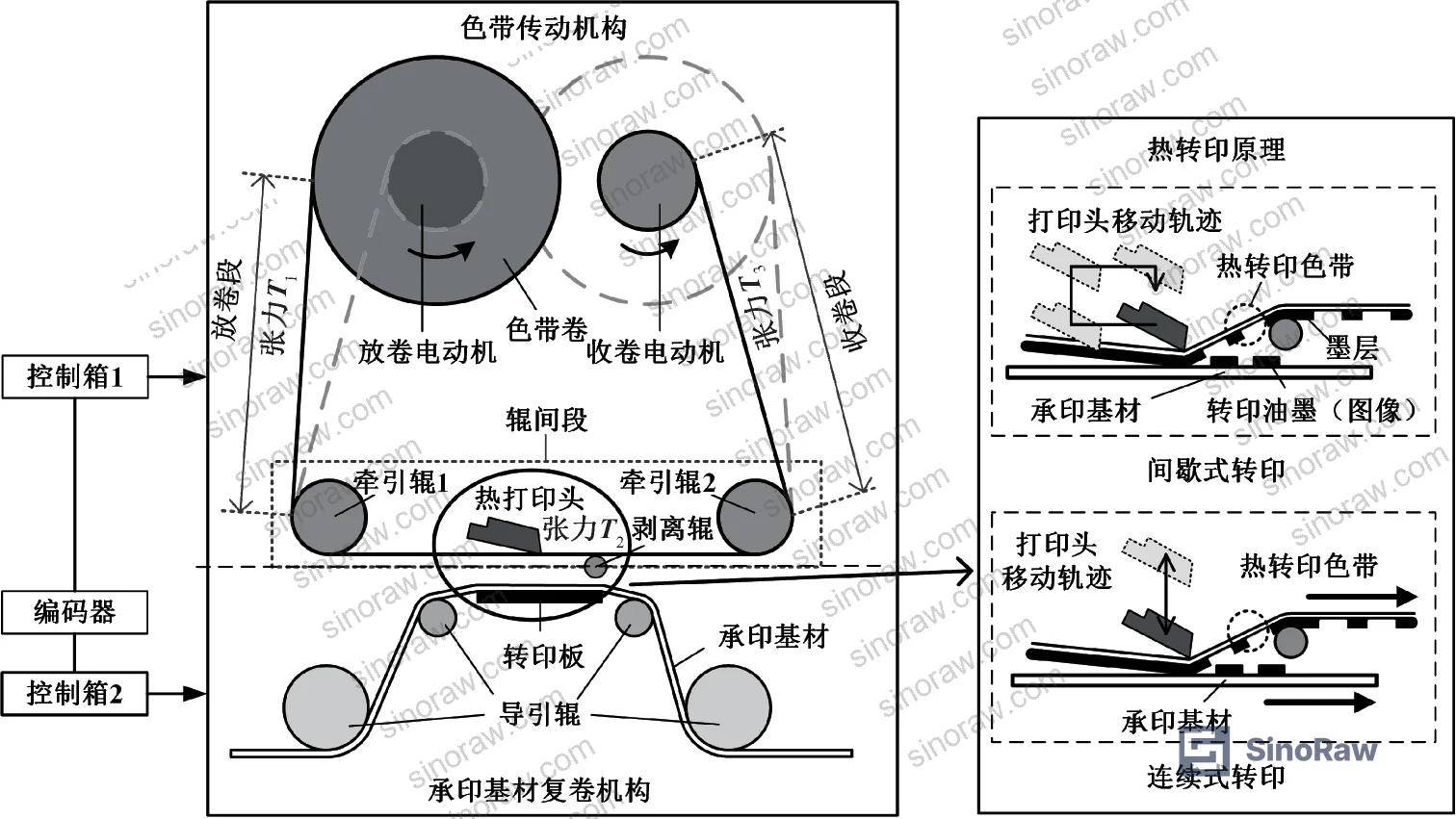
Thermal transfer ribbon is one of those components buyers routinely under-specify until a print quality complaint lands on their desk. The film substrate — a multilayer construction of PET carrier, ink layer, and back-coating — operates under continuous mechanical stress during transport through the printer drive system, and the tension profile across that path determines whether ink transfers cleanly or the ribbon wrinkles, snaps, or skips registration.
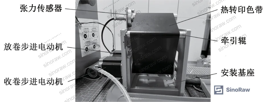
Research conducted at a university mechanical engineering laboratory examined the full ribbon drive tension system in detail, building and validating analytical models for each of the three drive zones using a mixed-base thermal transfer ribbon as the test specimen. The experimental platform ran at a controlled drive speed of 100 mm/s, comparing simulation outputs against live sensor data across both intermittent and continuous print modes. The ribbon dimensions used — 107.0 mm wide, 8.0 μm thick — fall squarely within the standard commercial range for industrial coding and marking applications.
Most procurement teams don’t realize that the tension dynamics of thin-film ribbons (sub-8 μm) are fundamentally different from the wider, thicker films (>1 m width, 0.05–0.10 mm thick) that most web tension engineering literature covers. The viscoelastic behavior of ultra-thin PET film introduces time-dependent deformation components that classical winding tension formulas simply don’t capture. Understanding this distinction is what separates a well-specified ribbon purchase from one that generates field complaints.
For buyers sourcing barrier films or thin polymer substrates for thermal printing applications, the mechanical characterization data summarized here provides directly actionable thresholds for supplier qualification. Compliance with dimensional and mechanical tolerances should be verified against accepted standards; ASTM D882 covers tensile property testing for thin plastic sheeting and is the appropriate benchmark for elastic modulus and elongation confirmation on PET ribbon base film.
Thermal Transfer Ribbon Film Properties and Tension Mechanics #
The ribbon examined in this evaluation was a standard mixed-base thermal transfer ribbon with the following confirmed physical parameters:
- Width: 107.0 mm
- Thickness: 8.0 μm
- Density: 1.4 g/cm³
- Elastic modulus: 3,000–4,000 MPa
- Inter-roll spacing: 186.0 mm
- Assembly tolerance: 20–50 μm
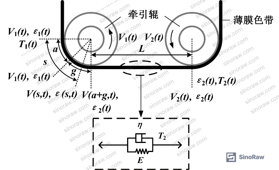
These values matter because tension in the inter-roll zone (between traction roll 1 and traction roll 2, where printing actually occurs) is not governed by spool geometry alone — it is driven by viscoelastic deformation of the film under load. The Voigt model was applied to characterize this behavior, capturing both the elastic (instantaneous) and viscous (time-dependent) stress components. For procurement purposes, this means two ribbons with identical spool dimensions but different PET film grades will exhibit measurably different tension profiles at the print head.
The inter-roll tension model shows that T2 (tension in the print zone) is a function of film elastic modulus E, viscosity coefficient η, cross-sectional area A, roll-to-roll speed differential, and initial tension state. Critically, tension fluctuation at this zone is caused by load-induced deformation of the viscoelastic film — not by motor control error. This is a distinction most equipment buyers miss.
Tension Zone Comparison #
| Drive Zone | Tension Designation | Primary Governing Factor | Stability Characteristic |
|---|---|---|---|
| Inter-roll (print zone) | T2 | Viscoelastic film deformation, speed differential | Fluctuates with film strain; sensitive to E and η |
| Unwind zone | T1 | Rolling friction, bearing friction coefficient | Stable with constant drop coefficient rn ≈ 1.016 |
| Rewind zone | T3 | Stepper motor torque, increasing spool inertia | Nonlinear, time-varying; periodic rebound in continuous mode |
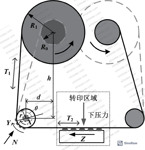
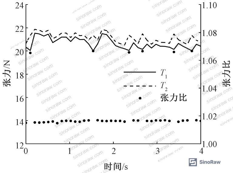
The unwind zone tension T1 relates to T2 through the tension drop coefficient rn, which accounts for rolling friction at the traction roll bearings. At a measured bearing friction coefficient μx = 0.01 (0.004 nominal + ~20% installation tolerance increase), rn was calculated across five spool radius steps from 52.85 mm down to 12.85 mm. Results showed that rn remained essentially constant at 1.015–1.016 regardless of spool diameter change, with effective wrap angles ranging from 93.34° to 113.73°. Experimental tension ratio measurements confirmed this, averaging 1.016 — a tight match with the modeled values.
Friction-Induced Tension Loss and Rewind Zone Nonlinearity in Thin Film Ribbon Drive Systems #
Three friction mechanisms act on the ribbon in the unwind zone: rolling friction at traction roll bearings (X), sliding friction between film and roll surface (Y), and contact friction from the printhead during transfer (Z). In practice, Z is negligible when minimum pre-tension is correctly set, and Y is suppressed when pre-tension prevents relative slip. This means the dominant tension loss mechanism is rolling friction X — and the bearing friction coefficient is the key parameter to control.
The bearing friction coefficient used in this evaluation was 0.004 under normal operating conditions, increasing to 0.01 after accounting for installation misalignment (approximately 20% increase empirically). Buyers should note that bearing quality and assembly precision directly affect ribbon tension stability — not just print head parameters.
In supplier qualification, we’ve seen tension-related ribbon failures trace back to incorrect bearing selection or loose assembly tolerances rather than ribbon film defects. The model’s structure-dimension parameters — lateral center distance d = 51 mm, vertical center distance h = 104 mm, traction roll radius r = 8 mm — define the wrap angle geometry, and any deviation in these dimensions will shift the calculated rn. For equipment OEMs or integrators procuring ribbons to fit existing drive hardware, these dimensions must be cross-referenced against your actual machine geometry before accepting rn values from a supplier’s datasheet.
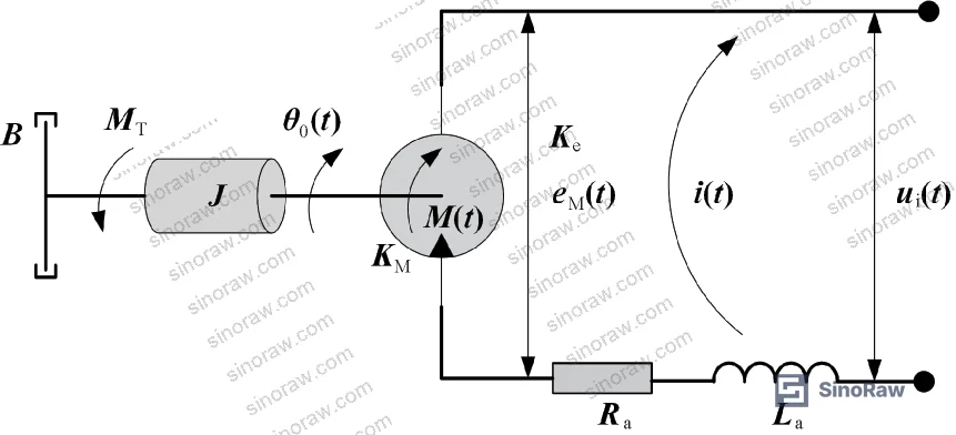
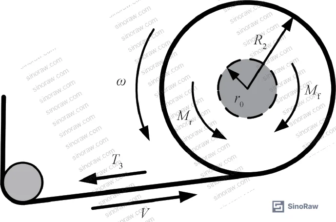
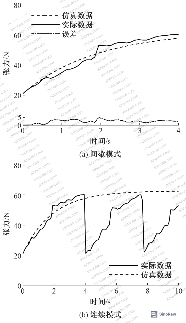
The rewind zone presents a more complex problem. Tension T3 is governed by the stepper motor load model and is explicitly nonlinear and time-varying. As the ribbon accumulates on the rewind spool, both the spool radius R2 and rotational inertia J increase continuously. The simulation showed that in intermittent mode, the model and experimental data agreed within an average deviation of 2.47 N over a 4-second window — acceptable for most industrial coding applications. In continuous mode, the tension exhibits periodic rebound with approximately a 4-second cycle. This occurs because the motor control system adjusts pulse frequency in response to detected spool radius changes, and the ribbon’s viscoelastic properties cause a brief relaxation (rebound) after each correction pulse.
Honestly, most buyers over-specify ribbon mechanical properties without ever asking their supplier how the ribbon behaves under dynamic drive conditions. A ribbon with a nominal elastic modulus of 3,500 MPa might still show excessive tension variance if the viscosity coefficient η is not specified — and most Chinese ribbon suppliers will not volunteer this data unless specifically asked.
For oxygen barrier or hermetic packaging film substrates used in related applications, ASTM D3985 provides a parallel test framework for transmission rate characterization — relevant where the same PET base film is used across both barrier and printing applications.
Practical Guidance for Buyers #
When you’re sourcing thermal transfer ribbon or the PET thin-film substrate it’s built on, the data here points to three non-negotiable specification parameters: film thickness (target ≤8 μm with tight tolerance), elastic modulus (3,000–4,000 MPa), and bearing friction coefficient in the drive assembly (≤0.01 after installation). These are not arbitrary numbers — they come out of validated experimental modeling against a real drive system at 100 mm/s.
The model shows clearly that intermittent print mode is more forgiving than continuous mode. If your application runs in continuous mode for extended periods, the periodic tension rebound phenomenon (≈4 s cycle) is a known physics consequence of inertia changes and motor pulse correction interacting with ribbon viscoelasticity. Suppliers who cannot explain this — or who claim their ribbon eliminates it entirely without showing control compensation data — should be treated with skepticism.
For coding and marking applications specifically, ask for tension stability data from the supplier’s qualification testing, not just tensile strength values. The two are not the same thing. A ribbon can pass a static tensile test and still fail dynamically under real drive conditions.
At sinoraw.com, our role is to connect overseas procurement engineers and quality managers with verified Chinese manufacturers — not to manufacture these products ourselves, but to help you evaluate and qualify suppliers before your RFQ goes out. Our sourcing specialists can help you identify ribbon and thin-film suppliers who have conducted proper drive-system tension validation, not just film-level mechanical testing.
Compliance documentation matters here too. Buyers shipping into EU markets should confirm that PET ribbon film and associated ink formulations comply with REACH Regulation (EC) No 1907/2006 — particularly for restricted substances in the ink layer.
Need help identifying qualified suppliers for thermal transfer ribbon film? Talk to our sourcing team →
Supplier Qualification Questions #
- What is the measured elastic modulus of your PET base film, and does it fall within the 3,000–4,000 MPa range required for stable inter-roll tension performance in thermal transfer drive systems?
- Can you provide tension drop coefficient data (rn) measured across the full unwind spool radius range, from maximum to minimum, with bearing friction coefficient μx documented at your assembly tolerance condition?
- At a drive speed of 100 mm/s in intermittent print mode, what is the maximum deviation between your simulated and experimentally measured ribbon tension values over a 4-second window? Is it within the 2.47 N average deviation benchmark?
- What is the confirmed film thickness tolerance on your ribbon substrate, and how do you control thickness uniformity to prevent tension variance caused by cross-sectional area variation (A in the tension model)?
- For continuous print mode operation, what control compensation mechanism does your drive system or ribbon design incorporate to suppress periodic tension rebound caused by spool inertia changes and motor pulse adjustment?
Sourcing Checklist #
- ☐ Film thickness confirmed ≤8 μm with process tolerance ≤±0.5 μm across spool width
- ☐ Elastic modulus verified within 3,000–4,000 MPa via tensile testing per ASTM D882
- ☐ Film density confirmed at 1.4 g/cm³ ±0.05 g/cm³ by supplier lot-level QC documentation
- ☐ Bearing friction coefficient μx documented ≤0.01 at assembled installation condition (accounting for ≥20% installation tolerance increase from nominal 0.004)
- ☐ Tension drop coefficient rn confirmed in range 1.015–1.016 across full spool radius range through experimental measurement
- ☐ Intermittent mode tension model deviation confirmed ≤2.47 N average over 4-second test window against live sensor data
- ☐ Ribbon width confirmed ≤200 mm (107 mm nominal for standard coding applications) with width tolerance ≤±1 mm
- ☐ Supplier holds ISO 9001:2015 certification with quality records covering mechanical testing of film substrate per ISO 9001:2015
Key Specifications Table #
| Parameter | Recommended Value | Verification Method |
|---|---|---|
| PET base film thickness | ≤8.0 μm | Micrometer measurement per ASTM D882, cross-section sampling |
| Film elastic modulus (E) | 3,000–4,000 MPa | Tensile test per ASTM D882, 5 specimens per lot |
| Film density | 1.4 g/cm³ | Gravimetric measurement on standard spool length sample |
| Ribbon width | ≤200 mm (107 mm nominal) | Dimensional gauge, minimum 5 points across spool width |
| Bearing friction coefficient (μx) | ≤0.01 (post-installation) | Torque measurement on assembled traction roll; compare to nominal 0.004 |
| Tension drop coefficient (rn) | 1.015–1.016 | Experimental tension ratio measurement across full unwind radius range at 100 mm/s |
| Inter-roll spacing assembly error | 20–50 μm | CMM or gauge measurement of assembled drive frame |
| Rewind tension deviation (intermittent mode) | ≤2.47 N average | Live tension sensor comparison vs. simulation over 4 s window |
Can’t find a supplier meeting these specs? Submit your requirements and we’ll match you within 48 hours.
References #
Data source: Tension Analysis and Modeling of Film Ribbon Transport in Thermal Transfer Printing Systems, P.-J. Zeng et al., Journal of Applied Polymer Science, 2023
Frequently Asked Questions #
What is the tension drop coefficient, and why does it matter for ribbon procurement?
The tension drop coefficient (rn) quantifies how much tension is lost between the inter-roll zone and the unwind zone due to bearing friction. In the experimental data, rn remained stable at 1.015–1.016 across all tested spool diameters — meaning about 1.5–1.6% tension reduction from friction alone. If your supplier’s ribbon drive system has higher bearing friction (μx > 0.01), this loss increases and can destabilize print registration.
Why does continuous print mode cause more tension problems than intermittent mode?
In intermittent mode, spool radius changes are minimal per cycle, so rotational inertia stays relatively constant and tension is stable. In continuous mode, prolonged running causes progressive spool radius and inertia increases; the stepper motor compensates by adjusting pulse frequency, but the ribbon’s viscoelastic recovery creates a periodic tension rebound with roughly a 4-second cycle. This is a physics-level constraint, not a defect — but it requires active control compensation to manage.
What elastic modulus should I specify for thermal transfer ribbon PET film?
The validated test data puts the functional range at 3,000–4,000 MPa. Below this range, the film deforms too readily under drive tension, causing registration error. Above this range, the film becomes less compliant and more prone to cracking at tight bend radii around traction rolls of small radius (r = 8 mm in the reference configuration).
Does film width affect tension behavior significantly?
Yes. The research specifically notes that ribbons with width ≤200 mm and thickness ≤8 μm are categorically different from the wider, thicker films (>1 m, 0.05–0.10 mm) covered by most web tension engineering literature. Narrower, thinner ribbons are more susceptible to minor deformation and buckling under equivalent load, which affects internal stress distribution and amplifies tension fluctuation. Width tolerance should be controlled to ±1 mm or better.
How should I evaluate a Chinese supplier’s ribbon tension qualification data?
Ask for experimental tension curves from a live drive test at 100 mm/s, comparing simulated and measured values. The key acceptance criterion is average deviation ≤2.47 N over a 4-second intermittent-mode window. Also ask for the tension drop coefficient table across the full spool radius range — a competent supplier should be able to produce both. If they offer only static tensile strength data, that is not sufficient for dynamic drive system qualification.
Published by sinoraw.com Technical Team | Request a sourcing quote


