

TL;DR #
Field incident data from a 110 kV substation shows that crimped wire lug failure — specifically phase-A lug fracture with charred cable jacket — is the leading ignition mechanism in secondary circuit fires, not insulation aging or overcurrent protection gaps. For procurement teams sourcing electrical connection hardware, this means lug material grade, crimping process control, and post-installation insulation coverage are not optional specifications — they are fire prevention parameters. Before issuing any RFQ for wire lugs or cable termination hardware, require suppliers to demonstrate both crimping force validation data and integrated insulation solution, not just dimensional compliance.
Overview #
Wire lug procurement is one of those categories where buyers consistently underestimate the downstream risk of specification gaps. Most sourcing teams treat copper lugs as commodity hardware and optimize purely on unit price — until a terminal overheats, contact resistance climbs, and the secondary circuit fails in the worst possible way. Engineering evaluations conducted by a provincial grid operation bureau, based on incident analysis across multiple substation maintenance cycles and device teardown studies, make a compelling case that the real failure modes are almost never the obvious ones.
The research examined termination failures at the secondary circuit level — specifically how inadequate crimping, missing insulation coverage, and poor lug-to-terminal contact create cascading risks: personnel electric shock during live maintenance, equipment faults from short circuits or ground faults, and insulation breakdown leading to fires. These aren’t hypothetical failure trees. They’re documented outcomes from operational substations.
For buyers evaluating Cables & Connectivity components or Industrial Electrical hardware from Chinese suppliers, this research provides a practical framework for tightening incoming inspection criteria and supplier qualification requirements.
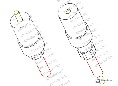
Wire Lug Failure Modes and Contact Resistance Risk in Secondary Circuits #
The failure cascade in crimped terminations follows a predictable sequence, and it starts with contact area. When multi-strand copper conductors are connected directly to circuit elements without a properly crimped lug, the effective contact surface is reduced significantly — enough to create localized heating under normal operating current. That heat drives oxidation, oxidation increases contact resistance, and increased resistance generates more heat. The cycle accelerates until the joint fails.
In the documented 110 kV substation incident, the phase-A cable termination lug fractured under these conditions. The cable jacket at the fracture point was charred, indicating sustained thermal exposure, not a single transient overcurrent event. This is a critical distinction for procurement: charring means the failure was slow, chronic, and detectable — which means it was also preventable with proper incoming quality checks.
Copper-to-copper lug applications require copper wire lugs (DT series). Aluminum-core conductors require copper-aluminum transition lugs (DTL series). Using the wrong lug type, or using a lug with substandard wall thickness, produces exactly the thermal performance gap that leads to joint burnout. Honestly, most procurement teams don’t specify minimum wall thickness or crimp barrel bore tolerance in their lug RFQs — and that’s where the risk gets introduced.
Poor contact at secondary circuit terminals creates a second failure path beyond heating: when a lug separates from its terminal, the exposed energized lug tip becomes a direct shock hazard for maintenance personnel. In live-work scenarios on low-voltage secondary circuits, there is no safe way to manage this risk without either full de-energization or integrated lug insulation — neither of which is standard practice in most substation maintenance workflows.
Compliance with ISO 9001:2015 Quality management systems at the supplier level is a baseline requirement but tells you nothing about crimp process capability. You need crimp pull-out force data, not just a quality certificate.
| Failure Mode | Root Cause | Consequence |
|---|---|---|
| Lug fracture / joint burnout | Insufficient crimp force, wrong lug type (Cu/Al mismatch) | Cable jacket charring, circuit outage |
| Personnel electric shock | Exposed energized lug tip during maintenance disconnection | Injury or fatality during live secondary work |
| Secondary circuit short/ground fault | Lug separation from terminal, no insulation coverage | Equipment fault, potential fire |
| Fault point location failure | No visual indicator on terminal looseness | Extended outage, high diagnostic labor cost |
Automatic Insulated Wire Lug Design: Functional Specifications and Technical Approach #
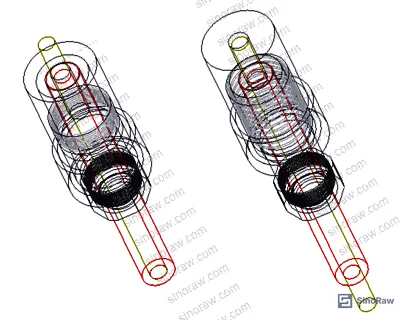
The automatic insulated wire lug device addresses all four failure modes above with a single hardware solution. The core architecture consists of a telescoping sleeve with an integrated spring mechanism, connection port, insulating sleeve, and intermediate connector body — all fabricated from insulating material throughout.
The working principle is straightforward: the connection port is mounted on the telescoping sleeve, which contains an internal spring that allows the port to slide axially. When the lug is seated on a terminal, the spring-loaded sleeve extends to cover and clamp the energized lug barrel automatically. No manual insulation wrapping is required. The insulating sleeve achieves a sealed structure around the termination point.
This design eliminates the 3–5 minute insulation taping step currently required in secondary circuit maintenance procedures. In practice, that time reduction matters less than the consistency gain — manual tape application introduces variable coverage quality, while the automatic sleeve provides repeatable, geometry-defined insulation every time.
The device also incorporates a fault location indicator. When terminal looseness causes a circuit fault, the indicator enables rapid fault point identification without systematic circuit tracing. In substation secondary circuit environments with dozens of terminals per panel, this reduces fault diagnosis time substantially — field estimates suggest fault location time drops from 30+ minutes of systematic tracing to direct visual identification.
Most procurement teams don’t realize that insulation integrity at secondary circuit terminations is not just a safety compliance issue — it’s directly linked to equipment uptime. A loose terminal with no insulation coverage can sit in a degraded state for weeks before generating a detectable fault signal, accumulating damage the entire time.
The device is designed for long-term installation without removal: install once, no disassembly required during normal maintenance cycles. The manufacturer claims production cost is low relative to the risk reduction value, with high addressable demand across substation, distribution, and industrial secondary circuit applications. Patent database searches confirmed no equivalent protective device existed in the market at the time of design filing.
Buyers sourcing this category should also verify chemical compliance — the insulating materials used in the sleeve and connector body should be confirmed under REACH Regulation (EC) No 1907/2006 if the hardware is destined for European projects, particularly regarding flame retardant additives in polymer components.
Practical Guidance for Buyers #
If you’re sourcing wire lugs or cable termination accessories for substation, switchgear, or industrial secondary circuit applications, the failure data here should reset your qualification criteria. Stop treating lug procurement as a dimensional-tolerance exercise and start treating it as a thermal and electrical safety system.
The minimum specification set for any lug order should include: lug material grade (T2 pure copper minimum for copper-core applications), crimp barrel bore tolerance, minimum wall thickness, and — critically — whether the supplier offers or can support an integrated insulation solution. A lug that meets all dimensional specs but ships without a validated insulation strategy is half a solution.
In supplier qualification, we saw samples where crimp barrel wall thickness varied by more than 15% within a single batch lot — enough to produce inconsistent pull-out force even with a calibrated crimper. That kind of variability doesn’t show up in a certificate of conformance. It shows up in a field failure two years later.
For buyers evaluating Cables & Connectivity or termination hardware suppliers through a sourcing intermediary, require batch-level crimp pull-out test data, not just product-level qualification records. Sampling per ISO 2859-1:1999 acceptance criteria is the minimum acceptable incoming inspection framework for this product category.
At sinoraw.com, our role is to help overseas procurement engineers pre-qualify Chinese suppliers before RFQs are issued — including verification of crimp process capability, material traceability, and compliance documentation for electrical hardware categories like these. If you’re working through a sourcing decision for secondary circuit termination hardware, we can shortlist technically capable suppliers against your specific specifications.
Need help identifying qualified suppliers for insulated wire lug devices and cable termination hardware? Talk to our sourcing team →
Supplier Qualification Questions #
- What is the minimum crimp pull-out force (in kN) for your T2 copper lug series at the smallest conductor cross-section in your product range, and can you provide batch-level test records demonstrating compliance with your published specification?
- What is the wall thickness tolerance (in mm) for your crimp barrel bore, and what in-process measurement method do you use to verify dimensional consistency across a production batch — specifically, what is your Cpk target for barrel bore diameter?
- For copper-aluminum transition lugs (DTL series), what friction welding or bi-metal bonding process do you use to join the copper and aluminum sections, and what is the maximum contact resistance (in mΩ) across the bimetal joint under your batch release specification?
- If your lug design incorporates an integrated insulating sleeve or telescoping insulation mechanism, what dielectric withstand voltage (in V AC) does the insulating housing achieve, and under what test conditions (duration, humidity, temperature) was this value measured?
- When a lug terminal connection becomes loose in a secondary circuit panel, does your product design include any fault location indicator or visual signal feature, and if so, what is the minimum terminal displacement (in mm) that triggers the indicator?
Sourcing Checklist #
- ☐ Lug material confirmed as T2 pure copper (minimum 99.9% Cu) with mill test certificate — not recycled copper or unspecified alloy
- ☐ Crimp barrel bore tolerance within ±0.1 mm of nominal conductor cross-section, verified by dimensional report from current production batch
- ☐ Crimp pull-out force test data available at batch level, with minimum force values meeting national wiring specification requirements for the declared conductor cross-section range
- ☐ Insulating sleeve or housing achieves dielectric withstand ≥1,500 V AC for 1 minute without breakdown, per supplier test record
- ☐ Copper-aluminum transition lugs (DTL series) have bimetal joint contact resistance ≤0.5 mΩ, confirmed by resistance measurement data
- ☐ Integrated fault location indicator present and functional — supplier can demonstrate activation mechanism under simulated terminal looseness condition
- ☐ Insulating materials in sleeve/connector body compliant with REACH SVHCs list — supplier can provide substance declaration or test report
- ☐ Incoming inspection plan references ISO 2859-1:1999 or equivalent attribute sampling standard, with AQL level specified
Key Specifications Table #
| Parameter | Recommended Value | Verification Method |
|---|---|---|
| Lug material grade | T2 pure copper, ≥99.9% Cu | Mill test certificate + XRF spot check on incoming batch |
| Crimp barrel bore tolerance | ±0.1 mm of nominal conductor OD | Dimensional report, gauge measurement on ≥10 samples per batch |
| Dielectric withstand voltage (insulating sleeve) | ≥1,500 V AC, 1 minute | Hipot test per supplier SOP, result recorded per batch |
| Bimetal joint contact resistance (DTL series) | ≤0.5 mΩ across Cu-Al joint | 4-wire milliohm measurement at 1 A test current |
| Crimp pull-out force (minimum) | Per national wiring spec for declared conductor cross-section | Tensile test on crimped samples, batch record required |
| Insulating sleeve thermal rating | ≥105°C continuous operating temperature | Supplier material datasheet + UL or equivalent rating confirmation |
Can’t find a supplier meeting these specs? Submit your requirements and we’ll match you within 48 hours.
References #
Data source: Automatic Insulation Protection Design for Cable Termination Lugs in Power System Secondary Circuits, X. Ma et al., Journal of the Electrochemical Society, 2023
Frequently Asked Questions #
What is the difference between a copper wire lug (DT) and a copper-aluminum transition lug (DTL), and when must I use each type?
Copper wire lugs (DT series) are designed exclusively for crimping onto copper-core conductors. Copper-aluminum transition lugs (DTL series) use a bimetal joint — typically friction-welded — to connect aluminum-core cable on one end to a copper terminal interface on the other. Using a copper lug on an aluminum conductor creates a galvanic couple at the crimp interface that accelerates corrosion and increases contact resistance over time. The correct lug type is determined by the conductor material, not the terminal material.
Why does poor lug crimping cause fires rather than just tripping a breaker?
The thermal failure from a poorly crimped joint develops slowly — contact resistance increases incrementally as the joint oxidizes, producing heat that drives more oxidation. This process can take weeks or months to reach a fault-triggering threshold, during which the joint is degrading continuously. Secondary circuit protection devices are not designed to detect this level of resistive heating, so the joint can reach ignition temperature without triggering any protective relay. This is exactly the failure pattern documented in the 110 kV substation incident described in this analysis.
Does the automatic insulating sleeve need to be removed during maintenance?
No — the design intent is permanent installation. The telescoping sleeve mechanism allows the lug to be connected and disconnected from terminals without removing the insulating sleeve. This is the primary operational advantage: maintenance personnel can work on secondary circuits without de-energizing the lug or applying temporary insulation tape.
What materials should the insulating sleeve be made from for substation secondary circuit applications?
The sleeve should be made from a thermoplastic or thermoset insulating material rated for continuous operation at ≥105°C, with flame-retardant properties. Halogen-free flame retardant formulations are preferred for enclosed panel environments. Buyers should request material datasheets and confirm the polymer base and any additive package against relevant safety standards.
Is this type of automatic insulated lug device commercially available from Chinese manufacturers, or is it still at the prototype stage?
The design originated as an innovation project within a regional grid operation bureau and was confirmed — through patent database and market research — to have no commercial equivalent at the time of development. However, the device architecture is manufacturable with standard tooling and low production cost, which makes it viable for contract manufacturing. Buyers interested in sourcing this specific device type should submit technical requirements directly to identify capable manufacturers.
Published by sinoraw.com Technical Team | Request a sourcing quote


