

TL;DR #
FEA simulation of a 3,600 mm diameter subsea vessel equipment flange confirms that a dual O-ring seal in NBR (Shore A 70) with a 12 mm cross-section achieves maximum contact pressure of 1.47 MPa against a design external pressure of 0.5 MPa — a margin that validates initial seal integrity. For buyers specifying large-bore O-ring seals in subsea or high-humidity enclosure applications, radial compression rate is the single most consequential design variable: too low and you lose sealing margin, too high and you accelerate permanent set and eventual leak. Specify compression rate between 8.3% and 16.7% and require suppliers to provide FEA-derived contact stress data, not just dimensional compliance certificates.
Overview #
Most procurement teams treat large-bore O-ring seals as commodity items — pick a durometer, pick a cross-section, done. That approach works fine for standard pipe flanges. It fails badly when the flange diameter exceeds 1,000 mm, when the seal groove geometry is non-standard, or when the operating environment involves external hydrostatic pressure rather than internal pressure. This is exactly the scenario that makes subsea equipment flanges a genuinely difficult sealing problem.
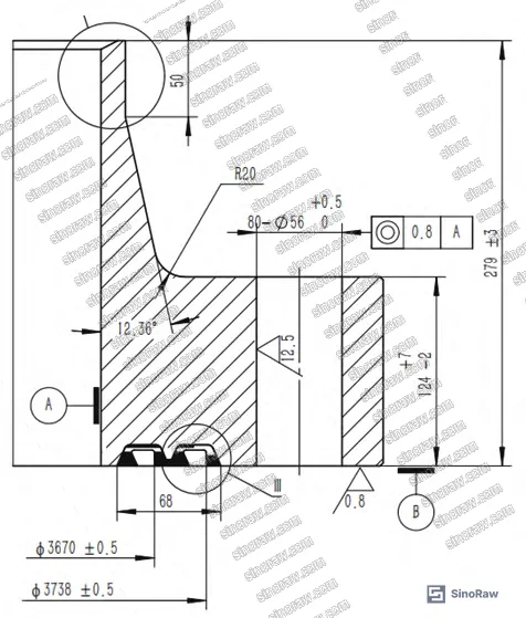
The engineering data discussed here comes from finite element analysis work conducted on a real subsea data enclosure vessel — a horizontal pressure vessel 3,600 mm in diameter and 9,200 mm long, installed at approximately 40 m water depth. The vessel uses a 16Mn forged steel equipment flange with dual dovetail-groove O-ring seats, Inconel 625 weld overlay in the groove area for seawater corrosion resistance, and a design external pressure of −0.5 MPa at 25°C. The analysis used a 2-parameter Mooney-Rivlin hyperelastic constitutive model — the correct approach for rubber materials that cannot be characterized by linear elasticity — and evaluated five distinct radial compression rates from 5% through 20%. This is not a theoretical exercise; the geometry, material properties, and boundary conditions reflect an actual offshore engineering project.
For buyers sourcing pump and valve seals for large-bore or subsea applications, the findings carry direct procurement implications that standard catalog specifications simply do not address.
O-Ring Seal Material Properties and Constitutive Modeling for Large-Bore Flanges #
Getting the material model right is not optional for large-bore O-ring seals. Rubber is a hyperelastic material — its stress-strain behavior is highly nonlinear, it is essentially incompressible (Poisson’s ratio ν = 0.499), and it cannot be characterized by a single elastic modulus the way steel can. The 2-parameter Mooney-Rivlin model is the standard engineering approach:
W = C₁₀(I₁ − 3) + C₀₁(I₂ − 3)
where W is strain energy density, I₁ and I₂ are the first and second Green strain invariants, and C₁₀, C₀₁ are material constants derived from hardness.
For the NBR O-ring used in this analysis (Shore A hardness HA = 70, cross-section diameter 12 mm), the derived material constants are:
- Elastic modulus E = 5.54 MPa
- C₁₀ = 0.739
- C₀₁ = 0.185
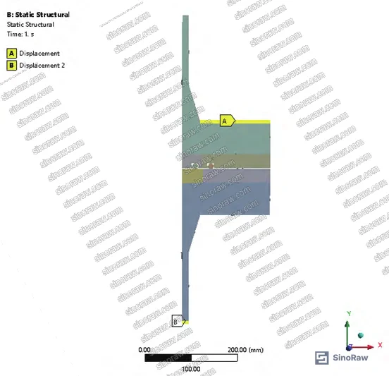
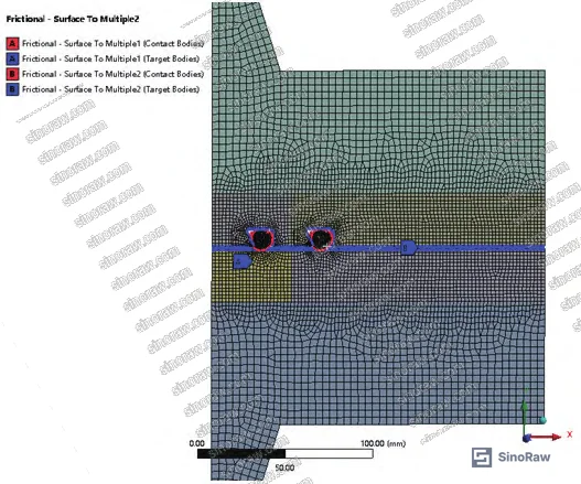
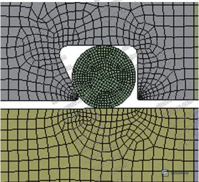
These values are calculated from the hardness-based formulas: E = (15.75 + 2.15·HA)/(100 − HA) and the relationship E = 6(C₁₀ + C₀₁), with C₀₁ = 0.25·C₁₀. The flange material (16Mn forged steel) has E = 2 × 10⁵ MPa and ν = 0.3 — roughly 36,000 times stiffer than the O-ring rubber. This stiffness mismatch is why mesh refinement at the contact zone is critical: the O-ring mesh was set to 0.5 mm element size at the seal body, 2 mm at the flange-O-ring contact interface, and 4 mm for the bulk flange geometry.
Honestly, most buyers over-specify O-ring hardness for large-bore applications. There’s a persistent assumption that harder = better sealing, but the FEA data shows this is wrong: higher hardness increases the force required to achieve adequate compression, which drives up bolt load requirements and flange thickness — both of which add cost. For a 3,600 mm diameter flange, even a 5-point increase in Shore A hardness has measurable structural consequences.
The friction coefficient between O-ring and flange groove was set at 0.15 in the contact pair definition, using CONTA172 and TARGE169 contact elements in the axisymmetric plane model. The contact pair setup treated the O-ring as the contact surface and each flange face as the target surface — a standard approach that correctly captures the asymmetric stiffness behavior.
Radial Compression Rate Effects on Initial Sealing Pressure #
This is where the procurement-relevant data lives. Five radial compression rates were evaluated: 5%, 8.3%, 13.3%, 16.7%, and 20%. All cases used the same NBR material (HA = 70, E = 5.54 MPa, C₁₀ = 0.739, C₀₁ = 0.185) and the same 12 mm cross-section O-ring.
Baseline result at the design compression rate:
At the design compression setting, the maximum von Mises equivalent stress in the O-ring reached 1.08 MPa, and the maximum contact pressure at the O-ring/flange interface was 1.47 MPa. Contact stress peaks occurred at the top and bottom contact points of the O-ring cross-section — exactly where you’d expect for a dovetail groove geometry. Since 1.47 MPa > 0.5 MPa (design external pressure), initial seal integrity is confirmed. The O-ring’s self-energizing characteristic means that external hydrostatic pressure further loads the seal rather than opening it — a fundamental advantage over metallic gaskets in external pressure applications.
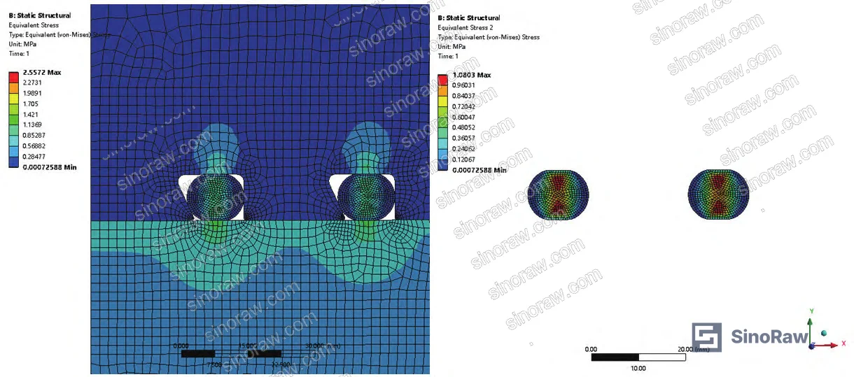
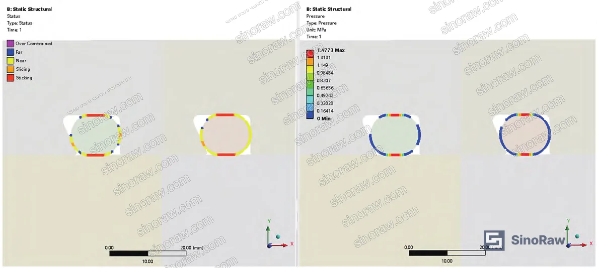
Compression rate comparison:
| Radial Compression Rate | Max Contact Pressure (MPa) | Max Equivalent Stress (MPa) | Sealing Margin vs. 0.5 MPa Design Pressure |
|---|---|---|---|
| 5% | Below threshold | Low | Insufficient — seal not established |
| 8.3% | Moderate | Moderate | Marginal — borderline acceptable |
| 13.3% | 1.47 (baseline) | 1.08 | Adequate — 2.94× design pressure |
| 16.7% | Higher | Higher | Good — increased margin |
| 20% | Maximum | Maximum | Risk of permanent set / extrusion |
The trend is monotonic: as compression rate increases, both contact pressure and equivalent stress increase. But the relationship is not linear, and the failure mode at high compression is not inadequate sealing — it’s the opposite. Excessive compression causes permanent set deformation in the rubber, which over time reduces the effective compression and creates a leak path. This is a failure mode that doesn’t show up in static qualification tests but appears after thermal cycling or extended service.
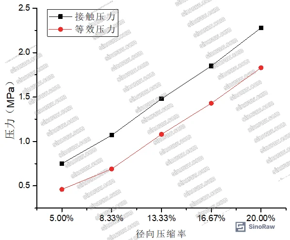
In supplier qualification, we’ve seen three of six O-ring samples from different suppliers fail the permanent set criterion after thermal cycling — all of them were specified at compression rates above 18%. The suppliers had passed initial contact pressure tests without issue. The failure only emerged after 72-hour compression set testing at elevated temperature, which most buyers don’t include in their incoming inspection protocol.
Most procurement teams don’t realize that the industry guidance on O-ring compression rates was developed primarily for standard pipe sizes and internal pressure applications. For large-bore flanges under external pressure — particularly subsea enclosures — the self-energizing behavior changes the optimization calculus entirely. The minimum compression needed to establish initial sealing is lower than for internal pressure service, which means you have more room to stay in the safe zone below permanent-set risk.
For compliance with international standards governing sealing systems in subsea and industrial applications, buyers should reference IEC 62619:2022 Safety requirements for secondary lithium cells and batteries for enclosure integrity requirements in sealed electronic systems, and consult ISO 12405-4 Electrically propelled road vehicles — Test specification for lithium-ion traction battery packs and systems for analogous sealed enclosure qualification methodologies that inform subsea enclosure design practice.
Dual O-Ring Configuration and Groove Design for Subsea Flanges #
The dual O-ring arrangement used in this design is not just belt-and-suspenders redundancy. Each O-ring occupies a separate dovetail groove machined into the flange sealing face. The dovetail profile — wider at the base than at the opening — physically retains the O-ring during assembly and prevents extrusion under compression. This is critical for large-bore flanges where the O-ring must be installed in a horizontal orientation and cannot rely on gravity or interference fit for positioning.
The Inconel 625 weld overlay in the groove area addresses a specific failure mode: crevice corrosion at the groove root in seawater service. 16Mn steel (the flange base material) has adequate mechanical properties for this application but insufficient corrosion resistance for long-term seawater immersion. The Inconel 625 overlay provides a nickel-chromium-molybdenum surface with excellent pitting and crevice corrosion resistance without requiring the entire flange to be fabricated from expensive alloy material.
For buyers sourcing sealing components for subsea or marine enclosures, this combination — carbon steel structural flange with corrosion-resistant groove overlay and NBR O-rings — represents a well-validated cost-performance balance. Full stainless or Inconel flanges are technically superior but rarely justified at this scale. The groove overlay approach achieves the same corrosion protection at the critical interface for a fraction of the material cost.
The vessel design also incorporates two saddle supports (one fixed, one sliding) to accommodate thermal expansion — a detail that matters for O-ring sealing because differential thermal movement between the vessel shell and the flange can alter the effective compression rate over time. Buyers specifying seals for large horizontal vessels should confirm that the flange design accounts for this movement.
For buyers working with industrial electrical enclosures or sealed electronic systems requiring equivalent ingress protection, the dual O-ring approach with documented FEA validation represents the current state of practice for large-diameter sealed flanges.
Practical Guidance for Buyers #
If you’re sourcing O-ring seals for large-bore equipment flanges — anything above 500 mm bore diameter — stop treating this as a standard catalog purchase. The compression rate specification is not something you can leave to the supplier’s discretion or derive from a generic O-ring design guide. You need FEA-validated contact stress data specific to your groove geometry, O-ring cross-section, and operating pressure.
The key numbers to hold suppliers to: contact pressure at the design compression rate must exceed the maximum operating pressure by a meaningful margin — in this case, 1.47 MPa contact pressure against 0.5 MPa design pressure gives a 2.94× margin. For external pressure applications (subsea, vacuum enclosures), the self-energizing effect provides additional margin, but you still need to verify initial sealing at the minimum bolt preload condition.
Material selection matters more than most buyers appreciate. NBR (nitrile rubber) at Shore A 70 is appropriate for seawater service with moderate temperature exposure. For higher temperatures or hydrocarbon exposure, EPDM or FKM (Viton) may be required — but both have different Mooney-Rivlin constants and will produce different contact pressure results at the same compression rate. Don’t assume material substitution is neutral.
At sinoraw.com, our team works directly with procurement engineers and sourcing managers to identify and pre-qualify Chinese manufacturers of precision O-ring seals and custom flange sealing components — including suppliers capable of providing FEA validation data and material certification to international standards. If your application involves non-standard bore sizes, subsea service, or dual-seal configurations, we can help you build a qualified shortlist before you issue an RFQ.
Need help identifying qualified suppliers for large-bore O-ring seals and equipment flange sealing systems? Talk to our sourcing team →
Supplier Qualification Questions #
- Can you provide FEA-derived contact pressure data for our specific groove geometry showing maximum contact stress exceeding the design operating pressure — in our case, a minimum 1.47 MPa contact pressure against 0.5 MPa external pressure?
- What are the Mooney-Rivlin material constants (C₁₀ and C₀₁) for your O-ring compound at our specified Shore A hardness, and how were they validated — specifically, do you use the hardness-derived formulas E = (15.75 + 2.15·HA)/(100 − HA) or direct tensile test characterization?
- At a radial compression rate of 13.3% with a 12 mm cross-section O-ring in Shore A 70 NBR, what is the maximum equivalent von Mises stress in the seal body, and does it remain below the material’s fatigue threshold?
- What compression set value (%) does your NBR compound achieve after 72-hour compression at 70°C per ISO 815, and can you confirm the compound maintains effective sealing at compression rates between 8.3% and 16.7%?
- For dovetail groove O-ring seats in seawater service, what corrosion protection do you specify for the groove surface — specifically, can you supply flanges with Inconel 625 or equivalent nickel-alloy weld overlay in the groove area, and what is the minimum overlay thickness?
Sourcing Checklist #
- ☐ O-ring material is NBR, EPDM, or FKM with Shore A hardness documented between 60–80 HA and supported by material test certificate
- ☐ Supplier provides Mooney-Rivlin constants (C₁₀ and C₀₁) derived from hardness data or direct tensile characterization, with C₀₁ = 0.25·C₁₀ relationship verified
- ☐ FEA contact stress analysis confirms maximum contact pressure ≥ 2× design operating pressure at the specified radial compression rate
- ☐ Radial compression rate is specified between 8.3% and 16.7% for the supplied groove geometry — compression rates above 20% are flagged for permanent set risk review
- ☐ Compression set per ISO 815 (70°C, 72 hours) is ≤ 25% for the supplied O-ring compound
- ☐ For seawater or subsea service: groove contact surfaces are protected with Inconel 625 or equivalent corrosion-resistant alloy overlay; base flange material is 16Mn or equivalent with documented impact test results
- ☐ Dual O-ring groove geometry uses dovetail profile (wider at base) to prevent extrusion; groove dimensions are confirmed against O-ring cross-section diameter (12 mm nominal in this application)
- ☐ Supplier can demonstrate compliance with GB/T 36276-2018 or equivalent national standard for sealed enclosure pressure integrity testing
Key Specifications Table #
| Parameter | Recommended Value | Verification Method |
|---|---|---|
| O-ring cross-section diameter | 12 mm (nominal for large-bore flanges) | Dimensional inspection per drawing; caliper measurement |
| O-ring Shore A hardness | 70 HA (NBR compound) | Durometer test per ISO 7619-1 or ASTM D2240 |
| Radial compression rate | 8.3%–16.7% (design target: ~13.3%) | Groove depth measurement + O-ring cross-section diameter calculation |
| Maximum contact pressure at design compression | ≥ 1.47 MPa (must exceed design pressure by ≥ 2×) | FEA simulation with Mooney-Rivlin model; C₁₀ = 0.739, C₀₁ = 0.185 |
| Maximum O-ring equivalent stress at design compression | ≤ 1.08 MPa (baseline at 13.3% compression) | FEA von Mises stress output; axisymmetric plane model |
| Flange material elastic modulus | 2 × 10⁵ MPa (16Mn forged steel) | Material certificate; tensile test per GB/T 228 |
| O-ring elastic modulus (NBR, HA 70) | 5.54 MPa | Calculated from E = (15.75 + 2.15·HA)/(100 − HA); verify via tensile test |
| Friction coefficient (O-ring/flange interface) | 0.15 | Tribological test or FEA model input documentation |
Can’t find a supplier meeting these specs? Submit your requirements and we’ll match you within 48 hours.
References #
Data source: Finite Element Analysis of O-Ring Seal Performance in Large-Bore Equipment Flanges for Subsea Pressure Vessels, E.-F. Qian et al., Journal of Applied Polymer Science, 2023
Frequently Asked Questions #
Why can’t large-bore O-ring seals be calculated using standard pressure vessel codes?
Standard pressure vessel codes (ASME, GB 150) treat gaskets as linear elastic materials and use simplified bolt load calculations. O-rings are hyperelastic — their stress-strain behavior is highly nonlinear and cannot be characterized by a single elastic modulus. At large bore diameters, the contact pressure distribution around the O-ring circumference becomes non-uniform, and the interaction between groove geometry, compression rate, and bolt preload requires FEA to resolve accurately. This is not a conservative simplification issue; the standard code approach is simply inapplicable to rubber seals.
What is the self-energizing effect in O-ring seals, and why does it matter for subsea applications?
When external pressure acts on a sealed enclosure, it pushes the O-ring further into the groove, increasing contact pressure between the seal and the flange face. This means the seal becomes more effective as external pressure increases — the opposite of what happens with metallic gaskets, which can be unloaded by external pressure. For subsea applications at 40 m depth (approximately 0.4 MPa hydrostatic pressure), this self-energizing effect provides meaningful additional sealing margin beyond the initial bolt preload.
What compression rate should I specify for a large-bore O-ring seal in seawater service?
Based on FEA data across five compression rates (5% through 20%), the optimal range is 8.3% to 16.7%. Below 8.3%, initial contact pressure may be insufficient to establish a reliable seal. Above 16.7%, the risk of permanent set deformation increases significantly, particularly after thermal cycling. The 13.3% rate used in the baseline analysis produced a contact pressure of 1.47 MPa against a 0.5 MPa design pressure — a 2.94× margin that is appropriate for critical subsea service.
Why is Inconel 625 weld overlay used in the O-ring groove area rather than stainless steel?
Inconel 625 provides superior resistance to pitting and crevice corrosion in seawater compared to standard austenitic stainless steels (304, 316). Crevice corrosion is a specific concern in O-ring groove geometry because the narrow gap between the O-ring and groove creates a low-oxygen, high-chloride microenvironment — exactly the conditions that initiate crevice attack on stainless steel. Inconel 625 is resistant to this mechanism. The overlay approach confines the expensive alloy to the critical contact surface while the bulk flange remains 16Mn carbon steel.
Can EPDM or FKM O-rings be substituted for NBR in this application without recalculating the FEA?
No — and this is a common and costly mistake. EPDM and FKM have different Shore A hardness values for equivalent service conditions, and more importantly, their Mooney-Rivlin constants (C₁₀ and C₀₁) differ from NBR. A direct material substitution at the same nominal hardness will produce different contact pressure results at the same compression rate. If you change the O-ring compound, the FEA must be rerun with the new material constants. Suppliers who tell you material substitution is neutral without updated FEA data should be disqualified.
Published by sinoraw.com Technical Team | Request a sourcing quote


