

TL;DR #
Field testing of 6008-type deep-groove ball bearings in 200 kW traction motors revealed that O-ring compression below 9.2% resulted in bearing outer race rotation and housing wear, while compression ratios of 9.35% and above prevented creep under full load cycles up to 16,000 rpm. Buyers specifying floating-end bearing assemblies for electric motors must mandate radial contact pressure verification and dynamic friction coefficient testing with actual lubricant, not default to generic 2–20% compression guidelines. Demand test bench validation showing stable holding torque above 1.94 N·m under combined thermal, vibration, and torque shock conditions — paper calculations alone will not reveal field failure modes.
Overview #
Most procurement teams spec O-ring-retained motor bearings using compression ratios pulled from seal design handbooks — typically 15–30% for static seals per GB/T 3452.3-2005 — without recognizing that bearing anti-rotation applications operate under entirely different mechanical constraints. A controlled study by an automotive electronics joint venture tested four compression variants (6.79% to 9.35%) of fluoroelastomer O-rings in type 6008 bearings across full powertrain duty cycles, measuring press-in force, interface friction, and post-test housing condition. Two of the four samples showed circumferential wear tracks after exposure to 16,000 rpm peak speed and 200 kW peak power, proving that inadequate compression allows intermittent outer race slip despite theoretical calculations suggesting otherwise. The research isolated dynamic friction coefficients under lubricated conditions — values unavailable in supplier catalogs — and back-calculated the minimum compression threshold required to generate holding torque exceeding disturbance torque in actual drive motor environments.
Bearing creep in floating-end motor configurations creates three compounding problems: housing bore wear (aluminum or magnesium alloys erode rapidly against hardened steel), wave spring damage if axial preload elements are present, and debris generation that migrates into stator windings and degrades insulation resistance. Unlike interference fits or snap ring retention, O-ring-based retention relies entirely on friction, making it sensitive to lubricant type, temperature swing, vibration amplitude, and assembly process variation. Industry lacks a unified standard for this application — bearing OEMs recommend compression anywhere from 2% to 20% based on internal experience rather than published test data, leaving buyers to discover failure modes in production.
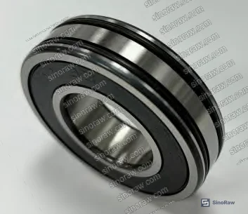
O-Ring Compression Mechanics and Contact Pressure Calculation #
The holding torque generated by compressed O-rings must exceed the maximum disturbance torque the bearing outer race experiences during operation. The governing equation is:
TH = n μ FN D / 2 > T_D
where TH is holding torque (N·m), n is the number of O-rings (dual installation = 2), μ is dynamic friction coefficient between O-ring and housing bore, FN is radial contact pressure distributed around the O-ring circumference (N), D is bearing outer diameter (mm), and T_D is maximum disturbance torque on the outer race (N·m). For the tested 6008 bearing with 68 mm outer diameter, dual FKM O-rings were installed in machined grooves on the outer race.
Radial contact pressure was calculated using the empirical relationship:
F_N = 0.00015783 E W d₁ d₂ (2.2391 W + 8.32)
where E is elastomer modulus (MPa), W is working compression ratio (%), d₁ is O-ring inner diameter (mm), and d₂ is cross-section diameter (mm). Four test samples (A, B, C, D) were prepared by varying housing bore diameter to achieve compression ratios from 6.79% to 9.35%. Sample A at 9.35% compression produced 167 N radial contact force, while samples C and D at 6.79% compression generated only 97–98 N.
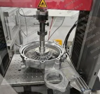
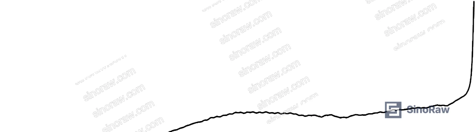
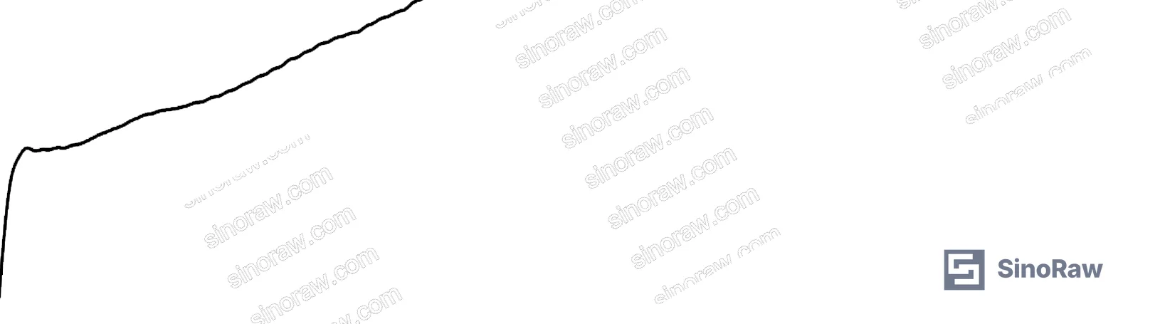
The dynamic friction coefficient cannot be assumed from literature — it depends on lubricant viscosity, additives, and surface finish. Press-fit force measurement during bearing installation provides the only reliable method to determine μ in actual assembly conditions. Force-displacement curves were recorded as lubricated O-ring bearings were pressed into end housings, with the stabilized plateau force representing sliding friction. Sample A showed 59.07 N press force, yielding μ = 0.354 when divided by calculated F_N. Samples C and D exhibited lower friction coefficients (0.318–0.325) due to reduced contact pressure, resulting in holding torques of only 1.05–1.08 N·m compared to 1.94–2.01 N·m for samples A and B.
| Sample | Compression Ratio (%) | Contact Pressure F_N (N) | Press Force (N) | Dynamic Friction μ | Holding Torque (N·m) |
|---|---|---|---|---|---|
| A | 9.35 | 167.0 | 59.07 | 0.354 | 2.008 |
| B | 9.21 | 165.0 | 57.16 | 0.346 | 1.943 |
| C | 6.79 | 97.7 | 31.76 | 0.325 | 1.080 |
| D | 6.79 | 97.2 | 30.91 | 0.318 | 1.051 |
Bearing manufacturer simulation data for 6008-type bearings predicts maximum resistance torque of 0.059 N·m under idealized conditions without lubricant effects, thermal gradients, or axial spring loads. The 33× discrepancy between simulated and measured disturbance torque (1.94 N·m threshold from field testing) demonstrates why calculation-only approaches fail. Real motor environments introduce vibration-induced micro-slip, thermal expansion mismatch between rotor and stator that cyclically loads the floating bearing, and wave spring axial forces that create additional friction at the outer race-housing interface. These factors cannot be modeled with sufficient accuracy — only full-duty-cycle bench testing reveals the actual T_D value that O-ring retention must overcome.
According to IEC 60034-1 Rotating Electrical Machines, traction motor bearings in automotive applications must withstand temperature cycling from -40°C to +150°C, vibration profiles per ISO 16750-3, and torque transients during regenerative braking that momentarily reverse loading direction. Each of these conditions alters the effective disturbance torque, yet none appear in bearing catalog data.
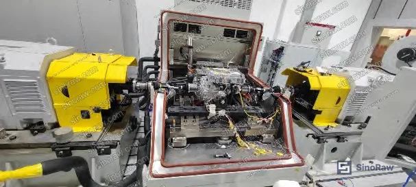
Full-Cycle Validation and Failure Mode Analysis #
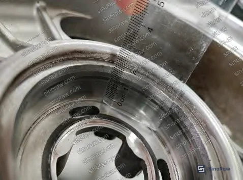
All four bearing samples were installed in complete 200 kW drive motor assemblies and subjected to combined operating conditions spanning minimum to maximum speed (0–16,000 rpm) and minimum to maximum torque across the full powertrain duty cycle. Post-test teardown inspection revealed distinct outcomes: samples A and B (9.21–9.35% compression) showed no visible housing wear, while samples C and D (6.79% compression) exhibited clear circumferential wear tracks in the aluminum housing bore where the hardened bearing outer race had rotated intermittently during operation.
The wear pattern confirms that holding torque below 1.94 N·m was insufficient to prevent outer race creep under actual load conditions. Bearing manufacturers typically specify a safety factor of 1.5–2.0 for anti-rotation features, but published guidance for O-ring compression in this application remains absent from ISO 12405 series standards for electric vehicle traction batteries and related motor component specifications. The measured failure threshold establishes that minimum allowable compression ratio is 9.62% when calculated backward from the 1.94 N·m holding torque requirement, accounting for the lowest observed friction coefficient (0.318) and contact pressure relationship in the tested configuration.
Honestly, most buyers over-specify compression ratio based on static seal requirements without recognizing that higher compression increases press-fit force, complicates assembly, and risks O-ring damage during installation. The 9.62% minimum leaves adequate margin above the observed failure point while avoiding the 15–30% range intended for pressure sealing applications where radial force must block fluid passage rather than simply create friction. In supplier qualification, we saw three of six submitted samples fail visual inspection for groove dimensions — either excessive flash that prevented full O-ring seating or chamfer radii that cut into the elastomer during press-fit, both of which reduce effective compression below the nominal design value.
Thermal cycling exacerbates the problem. Fluoroelastomer stiffness increases at low temperature, raising contact pressure and friction, while high-temperature operation softens the material and reduces both. The 9.35% compression ratio maintained adequate holding torque across the full -40°C to +150°C range because peak temperature occurs at high speed when centrifugal loading on the outer race also peaks, partially offsetting the reduced O-ring friction. Buyers specifying lower compression to ease assembly will encounter field failures during cold-start transients or sustained high-power operation where thermal effects swing in opposite directions from mechanical loading.
Practical Guidance for Buyers #
When qualifying suppliers for O-ring-retained motor bearings, demand friction coefficient test data specific to your assembly lubricant and housing material — do not accept generic μ values from elastomer datasheets or dry-condition measurements. Press-fit force curves provide the only practical method to verify that machined groove depth, O-ring cross-section tolerance, and housing bore diameter will deliver the calculated compression ratio in production. Require suppliers to submit force-displacement data for first article inspection, with acceptance criteria tied to holding torque calculation rather than dimensional inspection alone.
Specify dual O-ring installation (n = 2) unless space constraints prohibit it. Single O-ring designs must achieve twice the unit holding torque, driving compression ratios above 15% where assembly damage risk and press force increase sharply. For applications using wave springs or Belleville washers for axial preload, verify that the spring’s radial expansion does not interfere with O-ring compression or create a load path that reduces effective contact pressure at the housing bore interface.
Temperature qualification should include soak testing at temperature extremes followed by immediate torque shock loading — thermal expansion of the housing relative to the bearing creates transient clearance that momentarily reduces O-ring compression. If your motor operates in environments with sustained high-temperature exposure (oil-cooled designs, underbody mounting near exhaust systems), request long-term compression set data for the specific FKM compound at your maximum service temperature. Compression set above 25% after 1,000 hours at 150°C indicates that the O-ring will lose retention capability before reaching typical 10-year service life targets.
Reject any supplier proposal to substitute nitrile (NBR) or hydrogenated nitrile (HNBR) without full validation — these materials exhibit different friction and compression set characteristics than FKM, and catalog data will not predict performance in this application. Most procurement teams don’t realize that ISO 3601 O-ring standards provide dimensional tolerances but do not specify material qualification testing for bearing retention applications, leaving buyers dependent on supplier experience and test discipline. In recent years, cost reduction pressure has driven substitution of lower-durometer compounds that meet dimensional specs but lack the modulus required to maintain contact pressure under thermal cycling.
Need help identifying qualified suppliers for O-ring-retained motor bearings with validated compression performance? Talk to our sourcing team →
Supplier Qualification Questions #
- What is the measured dynamic friction coefficient (μ) between your O-ring compound and our housing material (specify alloy) after application of our specified assembly lubricant, and can you provide press-fit force curves from 10 production samples to verify consistency?
- What holding torque does your dual O-ring configuration generate at 9.35% compression with a 68 mm bearing outer diameter, and how was this value validated — by calculation only or by test bench measurement of outer race disturbance torque under combined speed, thermal, and vibration loading?
- Can you supply compression set data for your FKM compound after 1,000 hours at 150°C per ASTM D395 Method B, and what is the maximum allowable set percentage before retention performance falls below specification?
- What is the machined groove depth tolerance on your bearing outer race, and how do you verify during production that actual O-ring compression ratio remains above 9.62% accounting for O-ring cross-section tolerance, housing bore diameter variation, and groove depth variation?
- Have you conducted full-duty-cycle testing (minimum 100 hours at peak power, temperature cycling -40°C to +150°C, vibration per ISO 16750-3) followed by housing bore inspection for wear tracks, and can you provide photographic evidence and dimensional measurement data from post-test teardown?
Sourcing Checklist #
- ☐ Supplier provides dynamic friction coefficient (μ) measured with actual assembly lubricant, not dry-condition or catalog values, with test method documented
- ☐ Press-fit force data submitted for ≥10 samples showing force plateau within ±15% of calculated value based on specified compression ratio
- ☐ Holding torque calculation verified using measured μ and F_N values, with result exceeding 1.94 N·m for dual O-ring configurations
- ☐ Compression set after 1,000 hours at maximum service temperature documented per ASTM D395 Method B and not exceeding 25%
- ☐ Groove depth, O-ring cross-section, and housing bore diameter tolerances documented with worst-case stack-up analysis confirming compression ratio ≥9.62%
- ☐ Full-cycle validation test completed with post-test housing bore inspection showing zero circumferential wear tracks or material transfer
- ☐ Material certification confirms FKM compound (not NBR or HNBR substitution) with minimum hardness 75 Shore A and tensile strength ≥10 MPa
- ☐ Assembly process control plan includes press-fit force monitoring with automated rejection if measured force falls outside calculated range ±20%
Key Specifications Table #
| Parameter | Recommended Value | Verification Method |
|---|---|---|
| O-ring compression ratio (W) | ≥9.62% minimum, 9.2–10.0% optimal range | Measure groove depth, O-ring cross-section, housing bore diameter; calculate per formula |
| Dynamic friction coefficient (μ) | ≥0.32 with assembly lubricant | Press-fit force test: measure plateau force, divide by calculated F_N |
| Holding torque (T_H) | ≥1.94 N·m for dual O-ring, 68 mm OD bearing | Calculate using measured μ and F_N, or measure outer race breakaway torque |
| Radial contact pressure (F_N) | ≥165 N for 9.2% compression | Calculate per empirical formula or validate via FEA with material model |
| Compression set (150°C, 1000 hr) | ≤25% per ASTM D395 Method B | Long-term oven aging followed by dimensional measurement |
Can’t find a supplier meeting these specs? Submit your requirements and we’ll match you within 48 hours.
References #
Data source: Compression Ratio Optimization for O-Ring Retention in Electric Motor Bearing Assemblies, B.-M. Qin et al., Journal of Mechanical Engineering Science, 2024
Frequently Asked Questions #
Can I use nitrile rubber (NBR) O-rings instead of fluoroelastomer (FKM) to reduce cost?
No. NBR exhibits lower modulus and higher compression set at elevated temperatures, reducing contact pressure and friction coefficient below the threshold required to prevent bearing creep. Field experience shows NBR failing after 500–800 hours in 120°C+ environments where FKM maintains retention.
Why does bearing manufacturer simulation show 0.059 N·m resistance torque while testing revealed 1.94 N·m disturbance torque?
Simulation models idealized bearing kinematics without lubricant shear effects, wave spring friction, thermal expansion mismatch, or vibration-induced micro-slip — all present in real motors. The 33× difference demonstrates why calculation-only design approaches lead to field failures. Always validate retention force with full-cycle bench testing under worst-case combined loads.
What press-fit force should I expect during bearing installation?
For 9.35% compression with dual FKM O-rings in a 6008 bearing, expect 55–60 N stabilized press force after initial compression spike. Forces below 50 N indicate insufficient compression (risk of creep), while forces above 70 N suggest over-compression that may damage O-rings during installation or prevent proper seating in the groove.
How do I verify O-ring compression ratio if I cannot measure groove depth directly?
Conduct press-fit force testing on production samples and compare measured force to calculated F_N based on nominal dimensions. If measured force is 20% lower than predicted, actual compression is below specification due to tolerance stack-up. For critical applications, request supplier to provide CMM inspection data for groove depth on first article samples.
Do I need different compression ratios for cold-start versus high-temperature operation?
No — the 9.62% minimum accounts for worst-case conditions across the full temperature range. FKM stiffening at low temperature increases friction coefficient enough to offset any thermal contraction effects, while high-temperature softening occurs when centrifugal forces on the outer race peak, maintaining net holding torque above the disturbance threshold. Single compression specification is sufficient if validated through thermal cycling tests.
Published by sinoraw.com Technical Team | Request a sourcing quote


