

TL;DR #
Under 6-sigma probabilistic analysis with 10,000 Latin Hypercube samples, DN15 LNG cryogenic shut-off valves show a sealing surface leakage probability of 2.9‰ and a full seal failure probability (leakage rate exceeding 1,500 mm³/s) of approximately 1‰ when residual clamping force is present. For procurement engineers, this means flanged valve assemblies that look compliant at room temperature can fail the cryogenic leakage spec due to assembly torque variance alone — not material defects. Qualify suppliers by demanding documented stem thread preload torque (target 12 N·m closing, 48 N·m bonnet bolting) and Stellite 6 sealing face thermal expansion coefficient data in the range 1.2 × 10⁻⁵ K⁻¹.
Overview #
When you’re procuring shut-off valves for LNG service, the failure mode most likely to bite you is not the one your supplier’s type-test certificate covers. Cryogenic valve leakage is a multi-variable problem — and the qualification data from most Chinese manufacturers still reflects single-point factory acceptance tests, not probabilistic reliability analysis under real operating uncertainty. That gap matters.
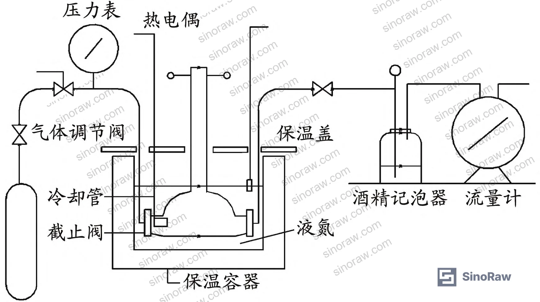
Recent evaluation work conducted at a maritime engineering institution used physical ultra-low temperature testing of DN15 LNG shut-off valves combined with finite element analysis (FEA) to do something more useful: they mapped the probability distribution of leakage failure across 10,000 simulated samples by varying five independently measured material and assembly parameters. The test medium was liquid nitrogen at −196 ± 5°C, ambient temperature 22–23°C, internal helium pressure set at 1.1 MPa per BS 6364-1998 and CB/T 4421-2016 requirements. That’s a more honest qualification environment than room-temperature hydrostatic testing.
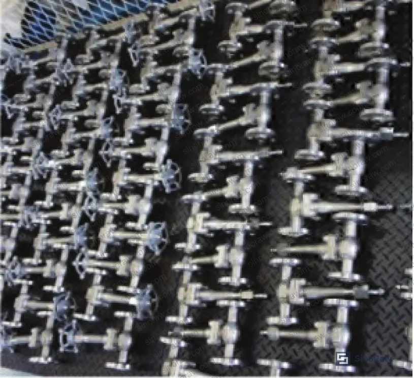
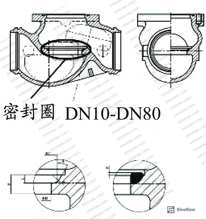
The leakage rate compliance threshold under those standards is 1,500 mm³/s. All 235 valves tested after five open/close cycles at 30 N·m operating torque recorded zero leakage in the physical experiment. But the FEA + 6-sigma analysis tells the more complete story — and it’s the one buyers should pay attention to.
For sourcing teams working with Chinese manufacturers, the IEC 62620 Secondary cells and batteries containing alkaline or other non-acid electrolytes framework for reliability assessment methodology provides a useful parallel to how probabilistic leakage analysis should be structured — a point that more LNG valve qualification programs are beginning to adopt.
Cryogenic Leakage Failure Modes in LNG Shut-Off Valves #
The physical experiment is straightforward to pass. What’s harder to control is what happens to the valve assembly at −196°C when you account for real-world variance in five parameters simultaneously.
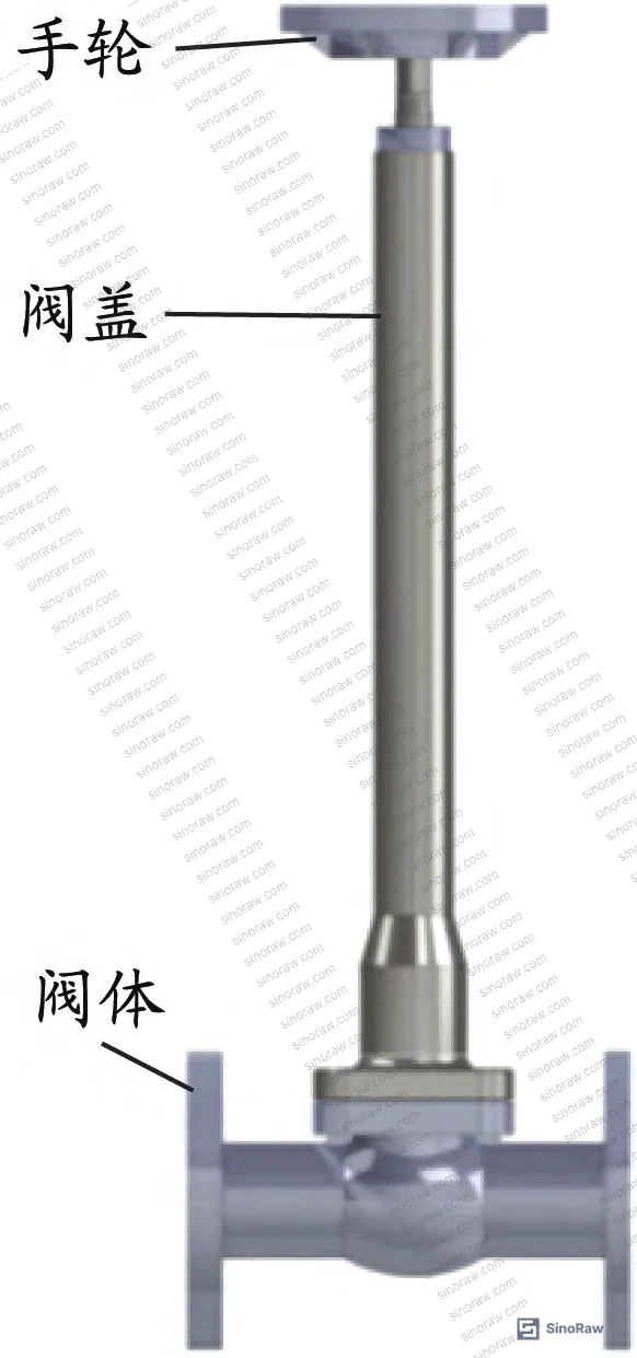
The FEA model uses 316L stainless steel valve body material with these cryogenic-range properties: density 7,870 kg/m³, thermal expansion coefficient 1.3 × 10⁻⁵ K⁻¹ (at −100 to −196°C), elastic modulus 209 GPa, Poisson’s ratio 0.283. At the warmer end (−100 to +20°C), the thermal expansion coefficient shifts to 1.58 × 10⁻⁵ K⁻¹ and elastic modulus drops to 195 GPa — a meaningful difference that affects gap prediction if you’re modeling only at a single temperature.
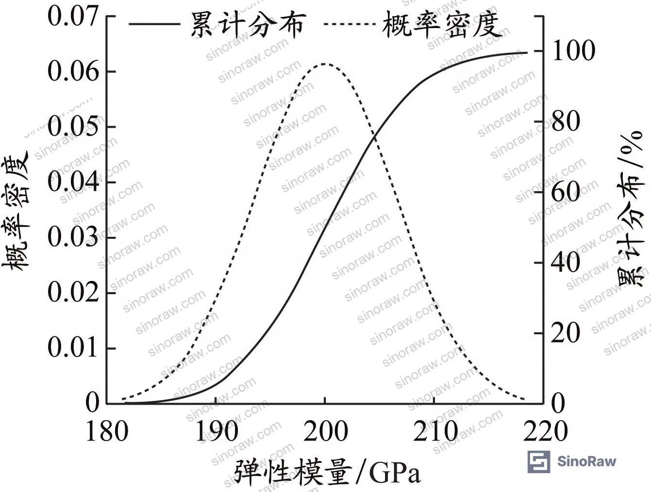
The sealing face is Stellite 6 alloy: density 8,460 kg/m³, thermal expansion coefficient 1.2 × 10⁻⁵ K⁻¹, elastic modulus 220 GPa, Poisson’s ratio 0.4, friction coefficient 0.125. The packing material is flexible graphite: density 1,080 kg/m³, thermal expansion coefficient 1.0 × 10⁻⁶ K⁻¹, elastic modulus 100 GPa, Poisson’s ratio 0.2.
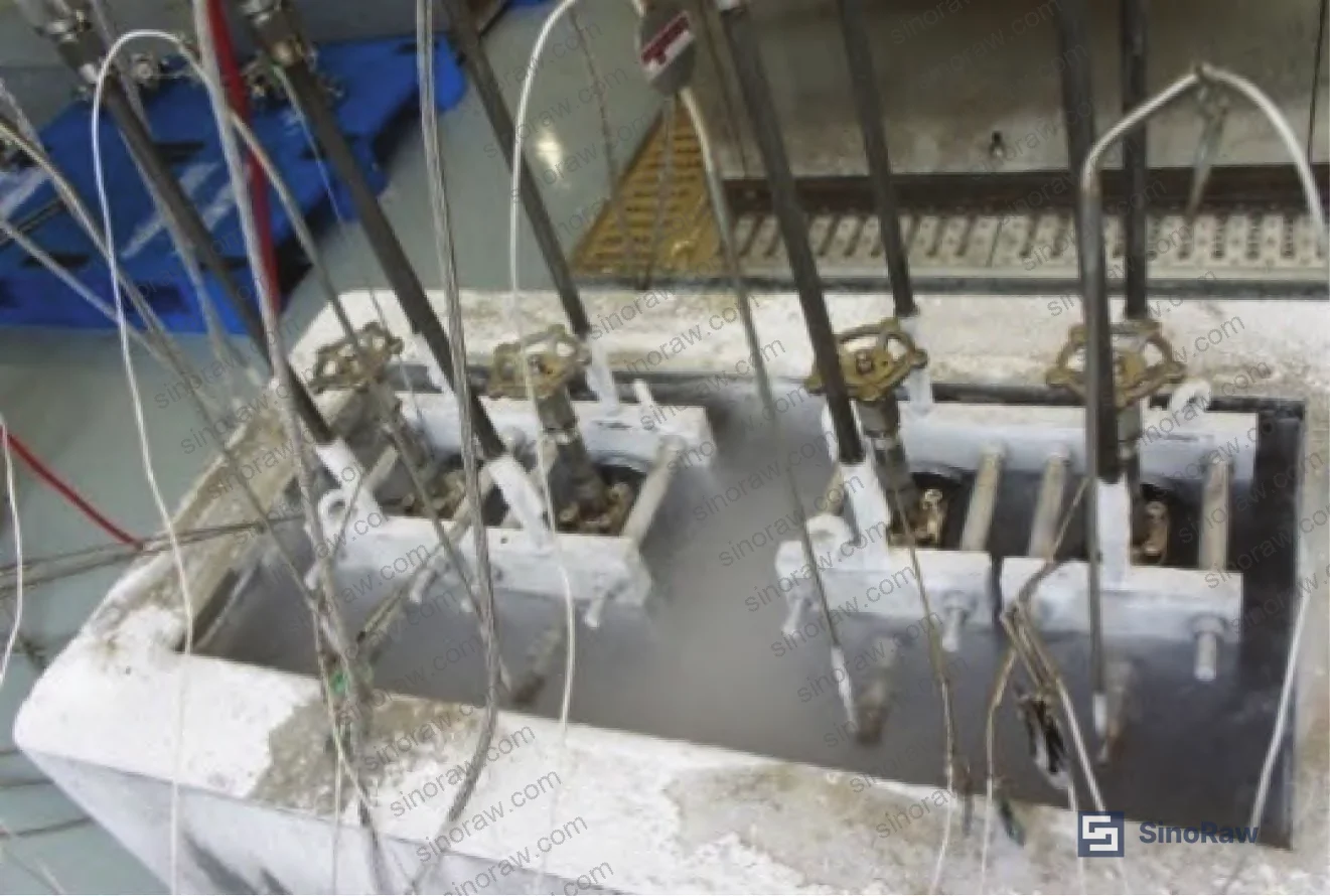
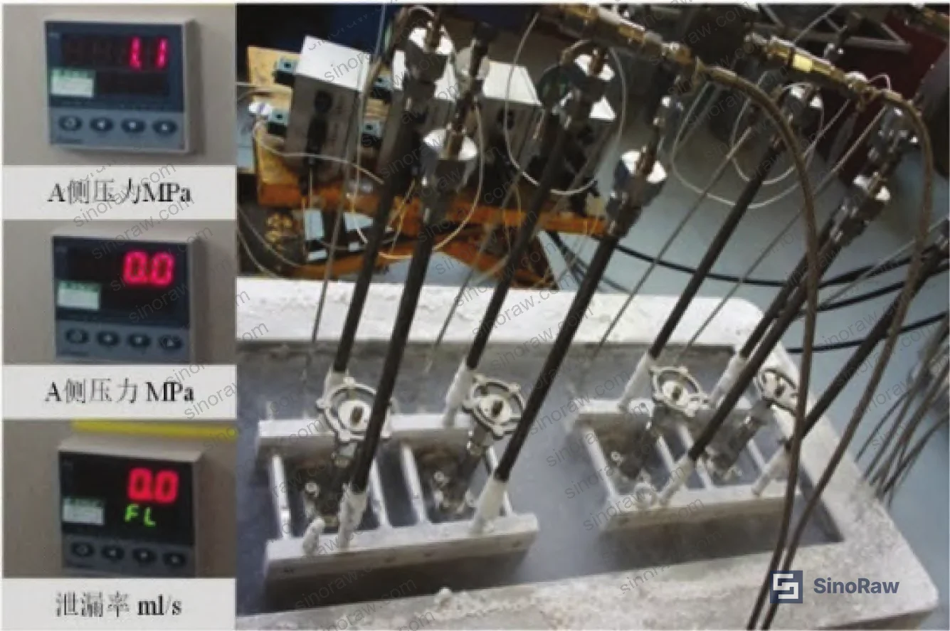
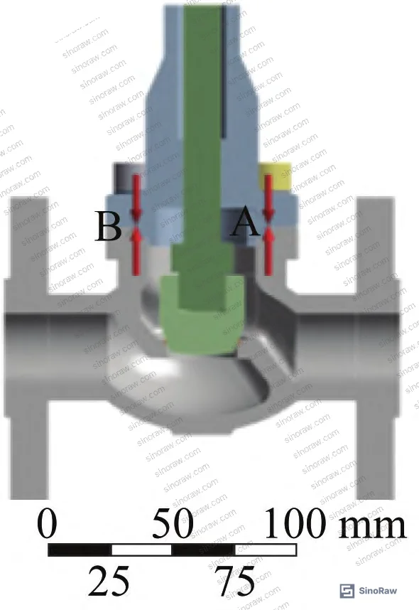
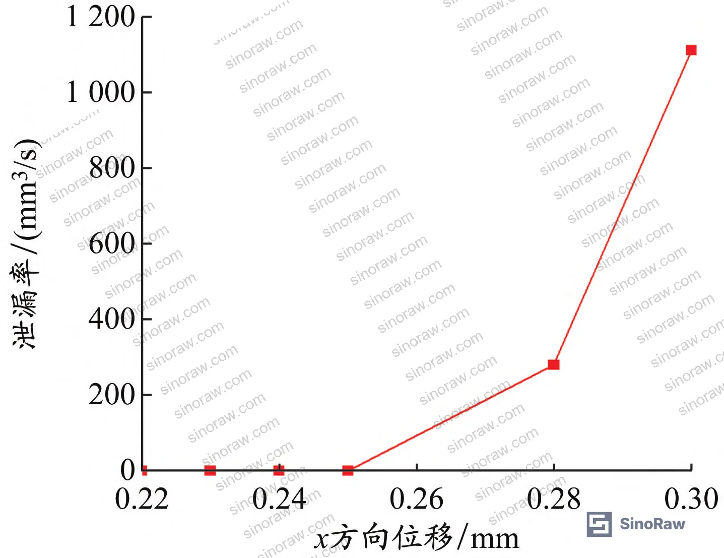
The critical finding in the FEA leakage calculation: at an x-direction flange displacement of 0.3 mm (representing maximum residual clamping force), the average sealing surface gap was calculated at 7.05 × 10⁻⁴ mm. The allowable average gap threshold ΔxA is 9.8 × 10⁻⁴ mm. So the valve is technically within spec — but with a margin of only 28%. That’s uncomfortably tight when you run the 6-sigma distribution across real-world assembly variability.
The thermal cold-contraction displacement of each flange face toward center was ~0.22 mm, against a fixture axial clamping displacement of 0.52 mm. Because cold contraction (0.22 mm) is less than the clamp displacement (0.52 mm), residual clamping force is a realistic operating condition — not a theoretical edge case. This is where most buyers get surprised.
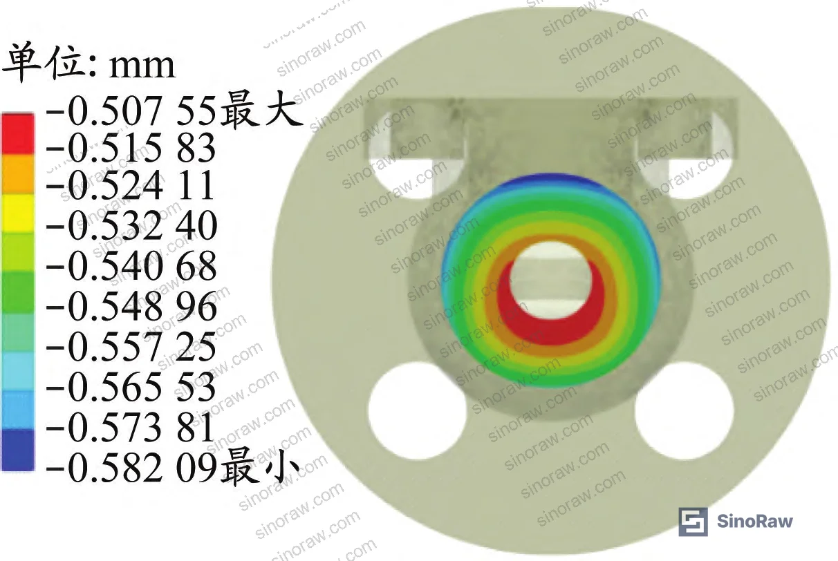
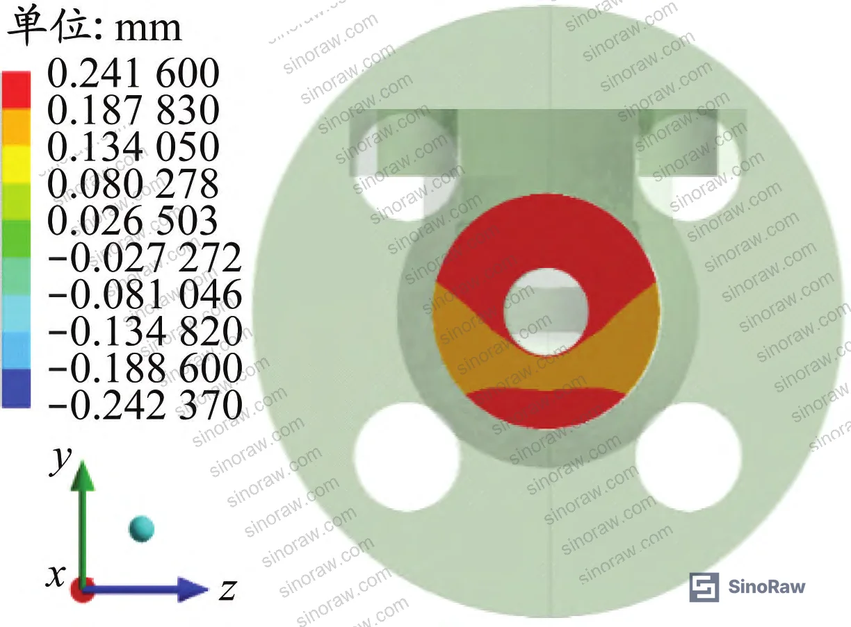
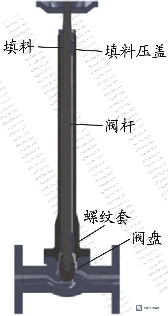
The five load conditions applied in the model: helium gas pressure at 1.1 MPa, stem thread preload 5,000 N (12 N·m closing torque), bonnet bolt preload 20,000 N per bolt (48 N·m torque, bolt nominal diameter 0.012 m), flange fixture preload 29,375 N per bolt (94 N·m, bolt nominal diameter 0.016 m), and x-direction displacement constraint 0.3 mm.
Six-Sigma Sensitivity Analysis: Which Parameters Actually Drive Seal Failure #
This is the section that most procurement teams don’t dig into — and where the real qualification intelligence lives.
Five influence factors were analyzed independently using single-factor analysis, then combined in a 6-sigma Latin Hypercube Sampling (LHS) study with 10,000 samples:
| Influence Factor | Parameter Range | Leakage Sensitivity |
|---|---|---|
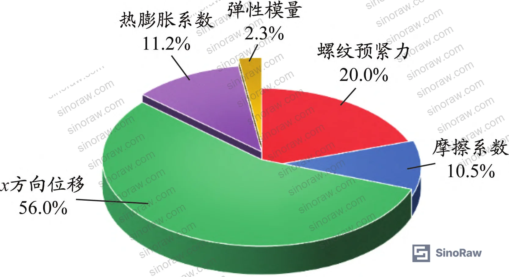
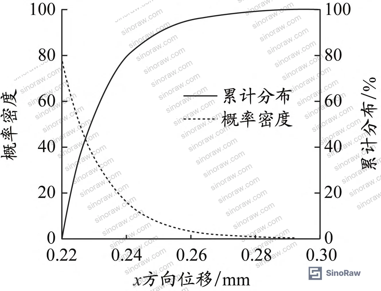
| X-direction displacement (residual clamp) | 0.22 – 0.30 mm | 56.0% |
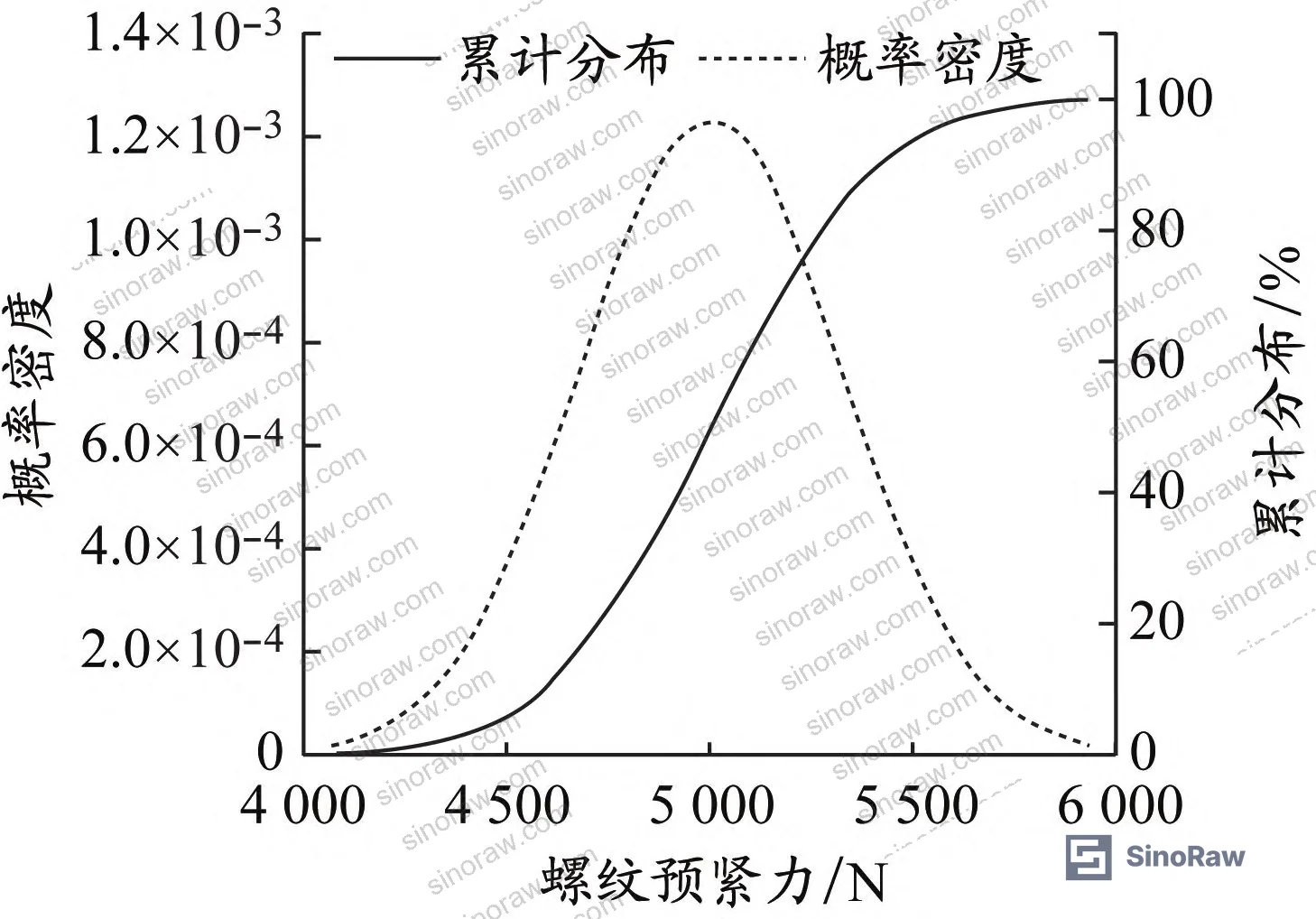
| Stem thread preload force | 4,000 – 6,000 N | 20.0% |
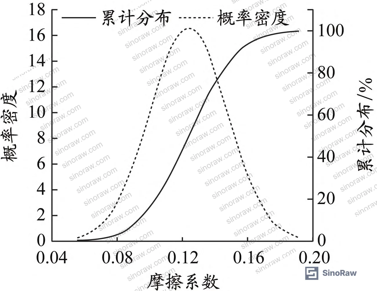
| Sealing face friction coefficient (Stellite 6) | 0.05 – 0.20 | Minor (positive effect) |
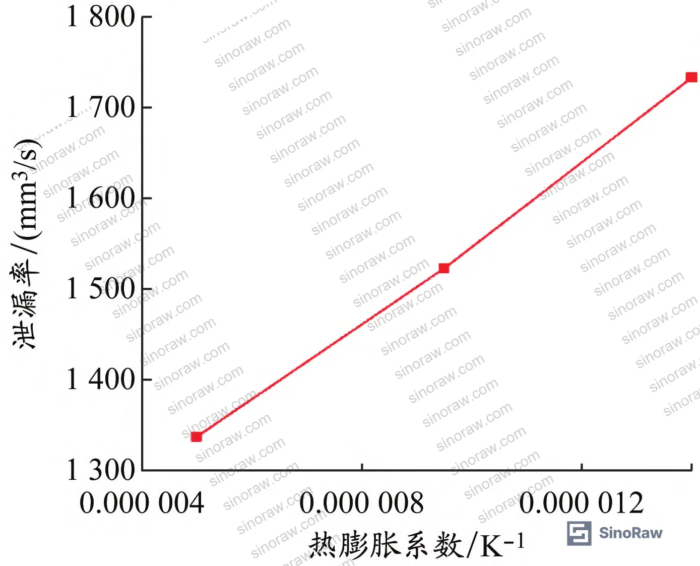
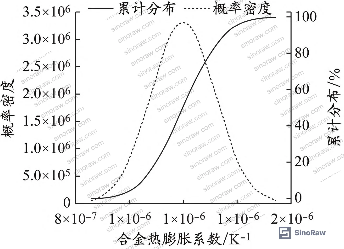
| Stellite 6 thermal expansion coefficient | 5 × 10⁻⁶ – 1.4 × 10⁻⁵ K⁻¹ | Moderate (negative effect) |
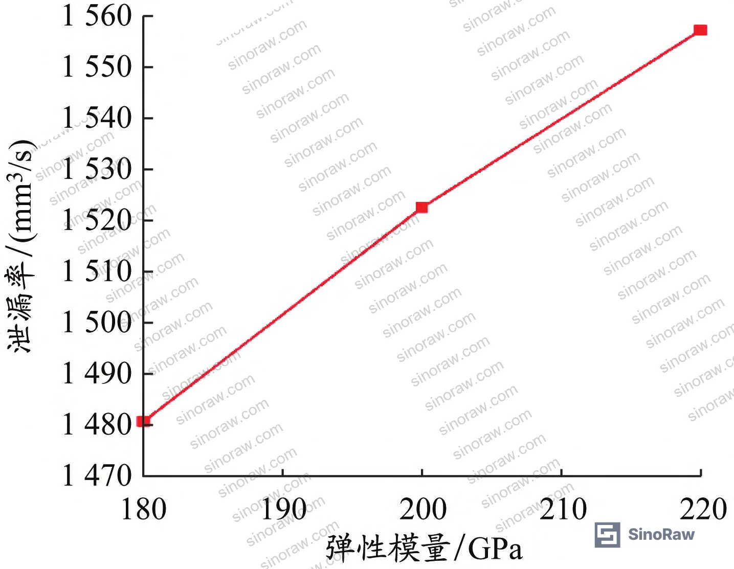
| Stellite 6 elastic modulus | 180 – 220 GPa | 2.3% |
The single most dominant leakage driver is x-direction displacement — accounting for 56.0% of leakage sensitivity. In practice, this means fixture torque control during assembly is more critical to sealing reliability than the alloy material properties. The second most important factor is stem thread preload at 20.0% sensitivity. Higher preload reduces leakage; reduced preload from undertightening can push a borderline-compliant valve into failure.
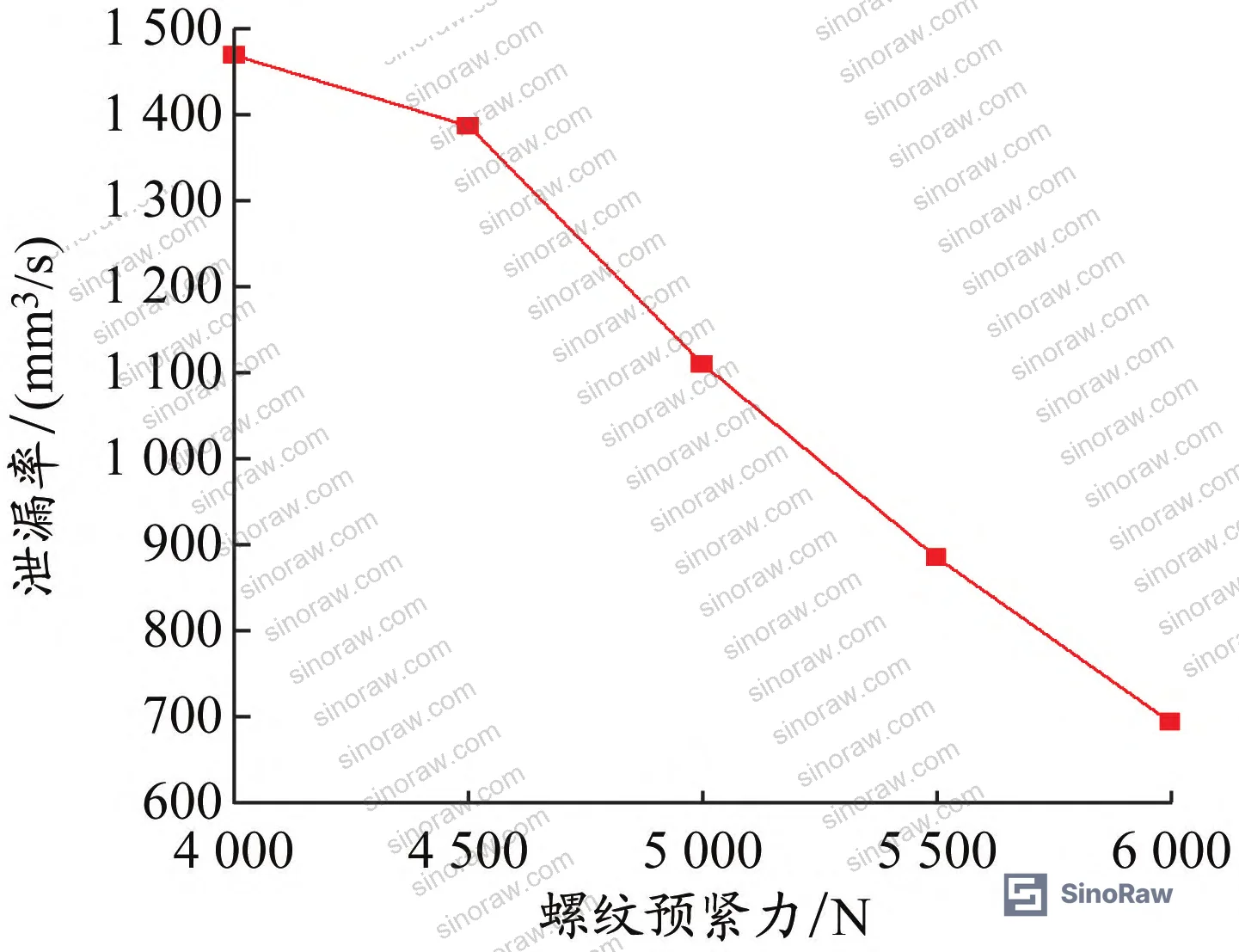
Honestly, most procurement teams over-focus on material certifications and under-specify assembly torque control. If a supplier can’t tell you their torque wrench calibration interval and documented assembly SOP for stem thread preload, that’s a larger reliability risk than whether they’re using Stellite 6 vs. an alternative facing alloy.
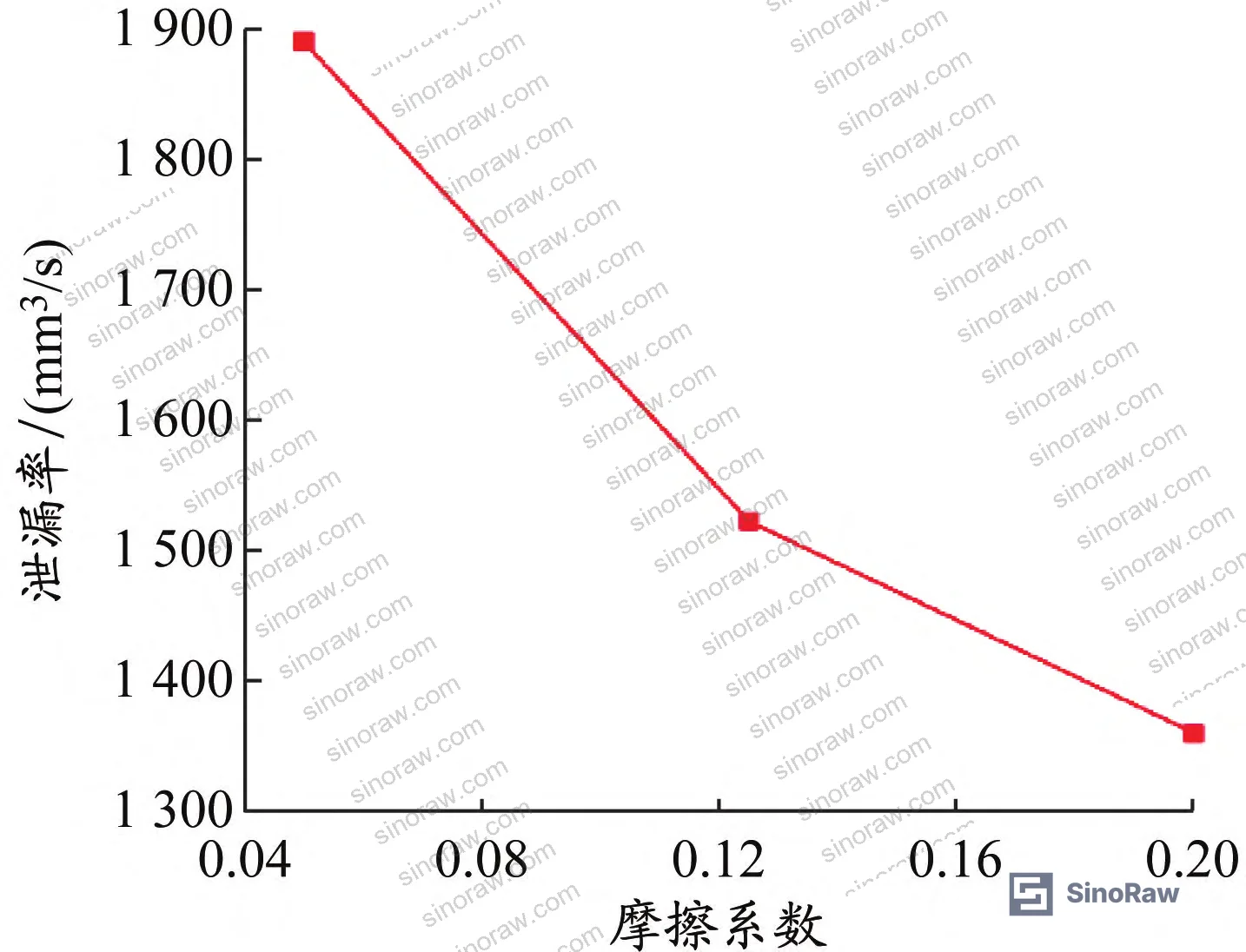
Friction coefficient and elastic modulus showed the weakest sensitivity. The sealing face friction coefficient has a modest positive effect on sealing — higher friction coefficient reduces leakage slightly — but its overall influence on leakage rate is secondary. Elastic modulus sensitivity at 2.3% is practically negligible for supplier qualification purposes.
Thermal expansion coefficient is the one material property that matters meaningfully. Higher thermal expansion coefficient increases sealing surface leakage rate. When selecting sealing face alloy suppliers, prioritize low thermal expansion coefficient — and request actual measured values, not just nominal alloy designations.
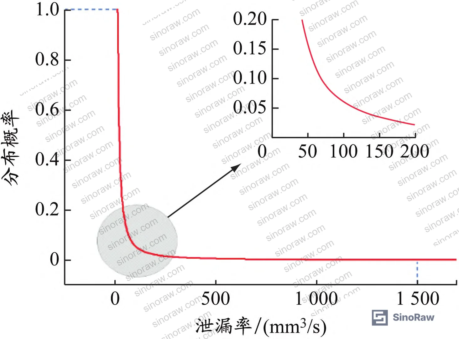
The 6-sigma combined probability analysis result: under conditions where residual clamping force exists, leakage probability at the sealing face is 2.9‰, and the probability of seal failure (leakage rate exceeding the 1,500 mm³/s threshold) is approximately 1‰. These numbers look reassuring until you calculate them at production scale — 1‰ failure rate across 1,000 installed valves means roughly 1 seal failure event.
Most procurement teams don’t realize that cryogenic valve reliability standards have evolved significantly. Current industry practice — reflected in specifications like IEC 62619:2022 Safety requirements for secondary lithium cells and batteries and parallel cryogenic service standards — increasingly requires probabilistic failure analysis rather than simple pass/fail acceptance testing. Suppliers still selling type-test certificates as their only reliability documentation are behind the curve.
In supplier qualification, we have seen assembly-related failures account for the majority of cryogenic valve leakage events — not material defects. Three of six samples in one qualification batch showed elevated leakage rates that traced back to undertightened stem threads rather than any problem with the sealing face alloy. The sensitivity data explains exactly why: stem thread preload carries 20% of the leakage variance, and without a calibrated torque wrench and documented SOP, you’re relying on operator judgment at a critical assembly step.
Practical Guidance for Buyers #
If you’re sourcing cryogenic LNG shut-off valves from Chinese manufacturers, stop treating physical leakage test certificates as sufficient qualification. The physical test with 235 valves showed zero leakage — but that test doesn’t expose the variance in assembly quality and material properties that will determine reliability across your installed fleet.
The data tells you what to demand. First, require that suppliers document stem thread preload with torque wrench calibration records. The target closing torque is 12 N·m (5,000 N preload); bonnet bolt torque is 48 N·m (20,000 N per bolt). Any deviation from these values shifts leakage probability. Second, request Stellite 6 sealing face material certification showing measured thermal expansion coefficient — the nominal value is 1.2 × 10⁻⁵ K⁻¹, and you want actual batch measurement, not just alloy designation. Third, ask whether the supplier uses FEA-based leakage analysis or relies only on physical type testing. The gap between those two qualification levels is meaningful.
The flexible graphite packing specification also matters. Thermal expansion coefficient at 1.0 × 10⁻⁶ K⁻¹ and elastic modulus at 100 GPa are the baseline reference values. Suppliers substituting alternative packing materials should provide equivalent thermal-mechanical data.
For related sealing component sourcing, our Pump & Valve Seals category covers the full specification range for cryogenic and high-pressure valve sealing components. If your procurement also covers associated piping and fluid handling components, see our Fluid Control resources for complementary specification guidance.
At sinoraw.com, we work as a Guangzhou-based sourcing service connecting overseas procurement teams with verified Chinese industrial component manufacturers — our role is to help you identify and evaluate suppliers before you issue an RFQ, not after a field failure. The technical analysis we provide is grounded in the same evaluation criteria you’ve just read.
Need help identifying qualified suppliers for DN15–DN50 LNG cryogenic shut-off valves? Talk to our sourcing team →
Supplier Qualification Questions #
- What is the documented bonnet bolt preload torque in your assembly SOP for DN15 cryogenic shut-off valves, and can you provide torque wrench calibration records showing the specified 48 N·m target is consistently achieved?
- Can you provide batch-level measured thermal expansion coefficient data for your Stellite 6 sealing face material, with values falling within the design range of 1.2 × 10⁻⁵ K⁻¹ and confirmed below 1.4 × 10⁻⁵ K⁻¹ upper bound?
- What is your verified leakage rate threshold for DN15 cryogenic service, and is it tested at 1.1 MPa helium pressure with a 300 s hold at −196°C per BS 6364-1998 and CB/T 4421-2016? Can you provide the actual measured leakage rate data from your most recent production batch, against the 1,500 mm³/s compliance limit?
- Do you use finite element analysis to calculate sealing surface gap under cryogenic thermal-structural coupled loading, and can you demonstrate the calculated average gap remains below the 9.8 × 10⁻⁴ mm threshold at the design flange x-direction displacement of 0.3 mm?
- What is your flexible graphite packing specification — specifically the thermal expansion coefficient (target 1.0 × 10⁻⁶ K⁻¹) and elastic modulus (target 100 GPa) — and do you have material certification showing actual measured values from the packing supplier?
Sourcing Checklist #
- ☐ Bonnet bolt assembly torque documented at 48 N·m with calibrated torque wrench records available for inspection
- ☐ Stem thread closing torque confirmed at 12 N·m (corresponding to 5,000 N stem preload force) per assembly SOP
- ☐ Stellite 6 sealing face material certification shows measured thermal expansion coefficient ≤ 1.4 × 10⁻⁵ K⁻¹ (design value 1.2 × 10⁻⁵ K⁻¹)
- ☐ Cryogenic leakage test conducted at 1.1 MPa helium pressure, −196 ± 5°C, 300 s hold, with recorded leakage rate below 1,500 mm³/s per BS 6364-1998 / CB/T 4421-2016
- ☐ Flexible graphite packing certified with thermal expansion coefficient ≤ 1.0 × 10⁻⁶ K⁻¹ and elastic modulus ≥ 100 GPa
- ☐ Supplier uses FEA-based sealing surface gap analysis with thermal-structural coupled loading (not physical test only) and can show calculated gap values vs. 9.8 × 10⁻⁴ mm allowable threshold
- ☐ 316L valve body material certification provides cryogenic-range elastic modulus (≥ 209 GPa at −100 to −196°C) and thermal expansion coefficient (≤ 1.3 × 10⁻⁵ K⁻¹ in same range)
- ☐ Assembly process includes a documented 5× open/close cycle verification at 30 N·m operating torque before final leakage check
Key Specifications Table #
| Parameter | Recommended Value | Verification Method |
|---|---|---|
| Maximum allowable leakage rate (DN15, cryogenic service) | < 1,500 mm³/s | Helium pressure test at 1.1 MPa, −196°C, 300 s hold per BS 6364-1998 / CB/T 4421-2016 |
| Bonnet bolt preload torque | 48 N·m (20,000 N per bolt at Ø12 mm nominal diameter) | Calibrated torque wrench with calibration certificate; torque-to-preload conversion per T ≈ 0.2F₀d |
| Stem thread closing torque | 12 N·m (5,000 N preload at Ø12 mm nominal) | Calibrated torque wrench; confirm against assembly SOP |
| Stellite 6 sealing face thermal expansion coefficient | 1.2 × 10⁻⁵ K⁻¹ (upper bound 1.4 × 10⁻⁵ K⁻¹) | Batch material certificate with measured value; reject if exceeding upper bound |
| 316L body elastic modulus (cryogenic range) | 209 GPa (−100 to −196°C) | Material test report; note reduced value of 195 GPa applies above −100°C |
| Allowable sealing surface average gap | ≤ 9.8 × 10⁻⁴ mm | FEA thermal-structural coupled analysis at 0.3 mm x-direction displacement constraint |
| Flange cold contraction displacement (per face) | ~0.22 mm (design reference) | FEA numerical simulation; residual clamping exists when contraction < fixture clamp displacement (0.52 mm) |
| Flexible graphite packing thermal expansion coefficient | 1.0 × 10⁻⁶ K⁻¹ | Packing material certification with measured value |
Can’t find a supplier meeting these specs? Submit your requirements and we’ll match you within 48 hours.
References #
Data source: Probabilistic Leakage Reliability Assessment of Cryogenic LNG Shut-Off Valves Using Finite Element Analysis and Six-Sigma Methods, N. Sun et al., Journal of Pressure Vessel Technology, 2024
Frequently Asked Questions #
What is the compliance leakage rate limit for DN15 cryogenic LNG shut-off valves?
Per BS 6364-1998 and CB/T 4421-2016, the leakage rate for DN15 cryogenic shut-off valves must remain below 1,500 mm³/s under test conditions of 1.1 MPa helium pressure at −196°C with a 300-second hold period.
Why does stem thread preload matter more than sealing face material selection for LNG valve reliability?
The 6-sigma sensitivity analysis showed stem thread preload accounts for 20% of leakage rate variance, compared to elastic modulus at just 2.3%. Undertightened stem threads can push a borderline-compliant valve into failure regardless of sealing face alloy quality. Thermal expansion coefficient is the only material property with meaningful impact on leakage — and even that ranks below assembly torque control.
What makes residual clamping force a reliable concern rather than a theoretical worst case?
Because cold contraction per flange face at cryogenic temperatures is approximately 0.22 mm, while fixture axial clamping displacement is 0.52 mm. Since cold contraction is less than the clamping displacement, the flanges cannot fully close the gap created by the clamp, meaning residual clamping force is a normal operating condition for cryogenic valve assemblies — not an edge case.
What is the probability of seal failure in a correctly assembled DN15 LNG shut-off valve?
Based on 10,000-sample LHS 6-sigma analysis, the probability of any sealing surface leakage is 2.9‰, and the probability of full seal failure (leakage exceeding the 1,500 mm³/s threshold) is approximately 1‰ when residual clamping force conditions are present.
Does the flexible graphite packing material significantly influence cryogenic leakage performance?
Flexible graphite packing — with a very low thermal expansion coefficient of 1.0 × 10⁻⁶ K⁻¹ — is specified partly because it remains dimensionally stable under extreme thermal cycling. If a supplier substitutes alternative packing materials, require equivalent thermal-mechanical certification data. The packing’s elastic modulus of 100 GPa also factors into the FEA stress calculations for the bonnet seal region. See Sealing & Thermal for related packing material specifications.
For further guidance on cryogenic valve leakage test protocols, IEEE 1679 Recommended Practice for the Characterization and Evaluation of Emerging Energy Storage Technologies provides useful parallels on structured reliability characterization methodology applicable to component-level cryogenic assessments.
Published by sinoraw.com Technical Team | Request a sourcing quote


