

TL;DR #
Fatigue fracture — not tensile overload — is the dominant failure mode for aluminum alloy electrical terminals operating under continuous vibration, and a terminal accumulating 1.6×10⁷ stress cycles at 1.86 Hz can fail with a sustained horizontal load as low as 18 kg if the cross-section geometry was never designed for cyclic loading. For procurement engineers specifying substation connectors and electrical clamping hardware, this means tensile strength spec compliance alone tells you almost nothing about service life. Require suppliers to document bending section modulus values and fatigue-rated load capacity before issuing any RFQ for vibration-exposed terminals.
Overview #
Most procurement teams evaluating aluminum electrical terminals focus almost entirely on alloy grade and tensile strength — and that’s an understandable starting point, but it misses the failure mechanism that actually takes components out of service. The analysis summarized here comes from a multi-method failure investigation conducted by a power grid research institute, examining three aluminum terminals pulled from active converter station service. The investigation combined dimensional measurement, optical emission spectroscopy, dye penetrant inspection, bending-to-fracture testing, and fracture surface analysis (both macroscopic and SEM-level) to reconstruct the failure sequence. What they found challenges some deeply held assumptions in how these components get specified.
The failed terminal had been in service for approximately 100 days when it fractured at the base of the threaded stud — the geometric stress concentration point. Two apparently intact sister terminals from the same installation were also retrieved and tested. All three showed some degree of pre-existing fatigue cracking before any deliberate mechanical load was applied. That’s the detail that should make any quality manager uncomfortable.
This type of industrial electrical component sits at an intersection of material science, vibration dynamics, and installation practice — all three of which contributed to the failure described here. Understanding all three is essential for writing a specification that actually protects your installation.
Alloy Substitution and Material Mismatch in Aluminum Electrical Terminals #
The spectroscopic analysis results here are worth looking at closely, because this is the kind of thing that slips through incoming inspection when buyers only verify certificates and skip alloy verification testing.
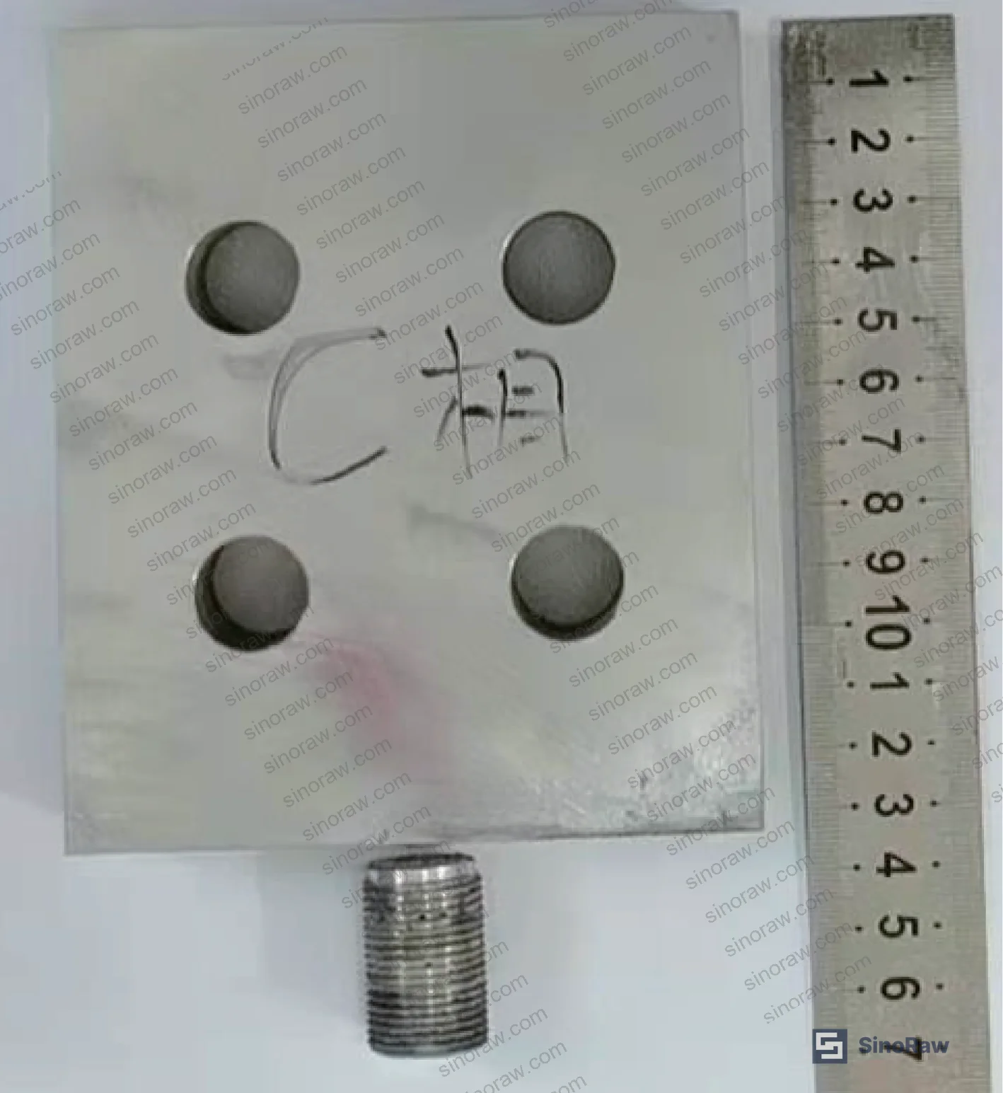
The three terminals — Phases A, B, and C — were nominally specified as 6061 aluminum alloy in T6 temper. Phase A and Phase B confirmed 6061 composition. Phase C, the one that fractured in service, came back as 6063.
| Parameter | 6061-T6 (Specified) | 6063-T6 (Actual — Phase C) | Difference |
|---|---|---|---|
| Min. Tensile Strength | ≥260 MPa | ≥215 MPa | −17% |
| Mg Content (%) | 0.8–1.2 | 0.65 (measured) | Below spec |
| Cu Content (%) | 0.15–0.4 | 0.034 (measured) | Below spec |
| Si Content (%) | 0.4–0.8 | 1.27 (measured) | Above 6061 range |
Reference standard for mechanical properties: BS EN 755-2:2008 (Aluminium and aluminium alloys — Extruded rod/bar, tube and profiles — Mechanical properties). The chemical composition verification followed GB/T 3190-2020.
Now, the important nuance: the 17% tensile strength deficit is real, but the investigation concluded that alloy substitution was not the primary cause of fracture. Why? Because Phases A and B — both correctly specified 6061 — also showed pre-existing fatigue cracks at the same location during penetrant inspection. The material substitution was a supplier quality failure, but the structural design failure was the bigger problem. Both matter. Don’t let the alloy story distract you from the geometry story.
Honestly, most buyers over-specify alloy purity tolerances while under-specifying the mechanical geometry — bending section modulus, fillet radius at stress concentrations, and fatigue-rated load capacity. Those are the numbers that determine whether a terminal survives 10⁷ cycles.
Compliance with ISO 9001:2015 Quality management systems does not prevent alloy substitution — it only requires that a supplier have a process for controlling materials. Verifying that process with incoming spectroscopic spot-checks on every batch is the only reliable countermeasure.
Fatigue Fracture Mechanics: How 1.86 Hz Destroys a Terminal in 100 Days #
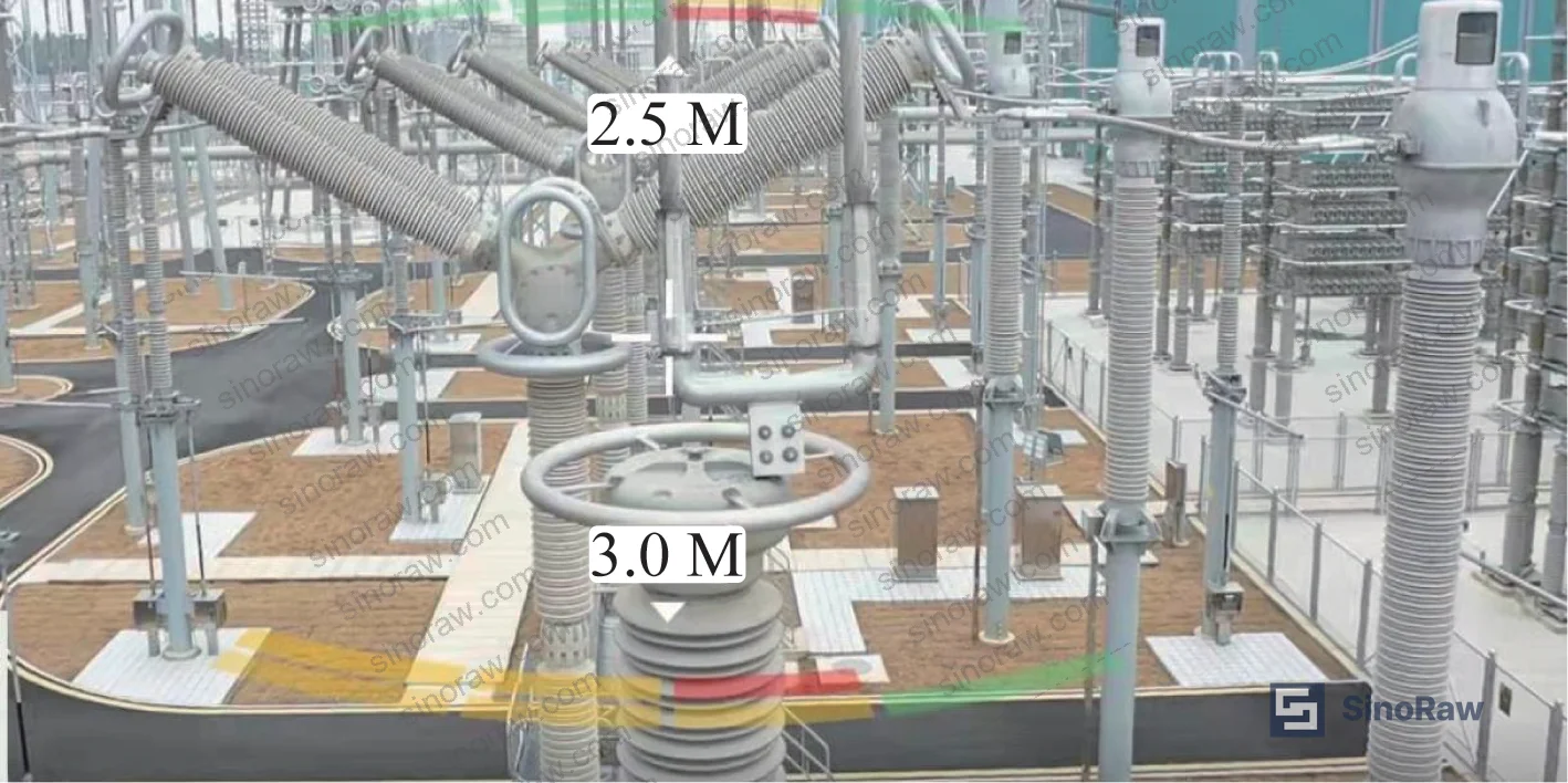
This is where the analysis gets technically instructive. The voltage transformer in this installation operated with a characteristic vibration frequency of 1.86 Hz. That seems low — barely perceptible to a human — but over 100 days of continuous operation, it accumulates to:
100 days × 24 hours × 3,600 seconds × 1.86 Hz = 16,070,400 cycles ≈ 1.6×10⁷ stress cycles
The terminal’s design had never been evaluated against fatigue loading. The cross-sectional geometry at the stud root — the location of maximum bending stress — was sized for static load resistance only. Using the 6061-T6 fatigue data at 2×10⁷ cycles, the maximum horizontal load the original terminal could sustain under long-term cyclic conditions was approximately 18 kg (176 N). That is a strikingly low number for a substation component.

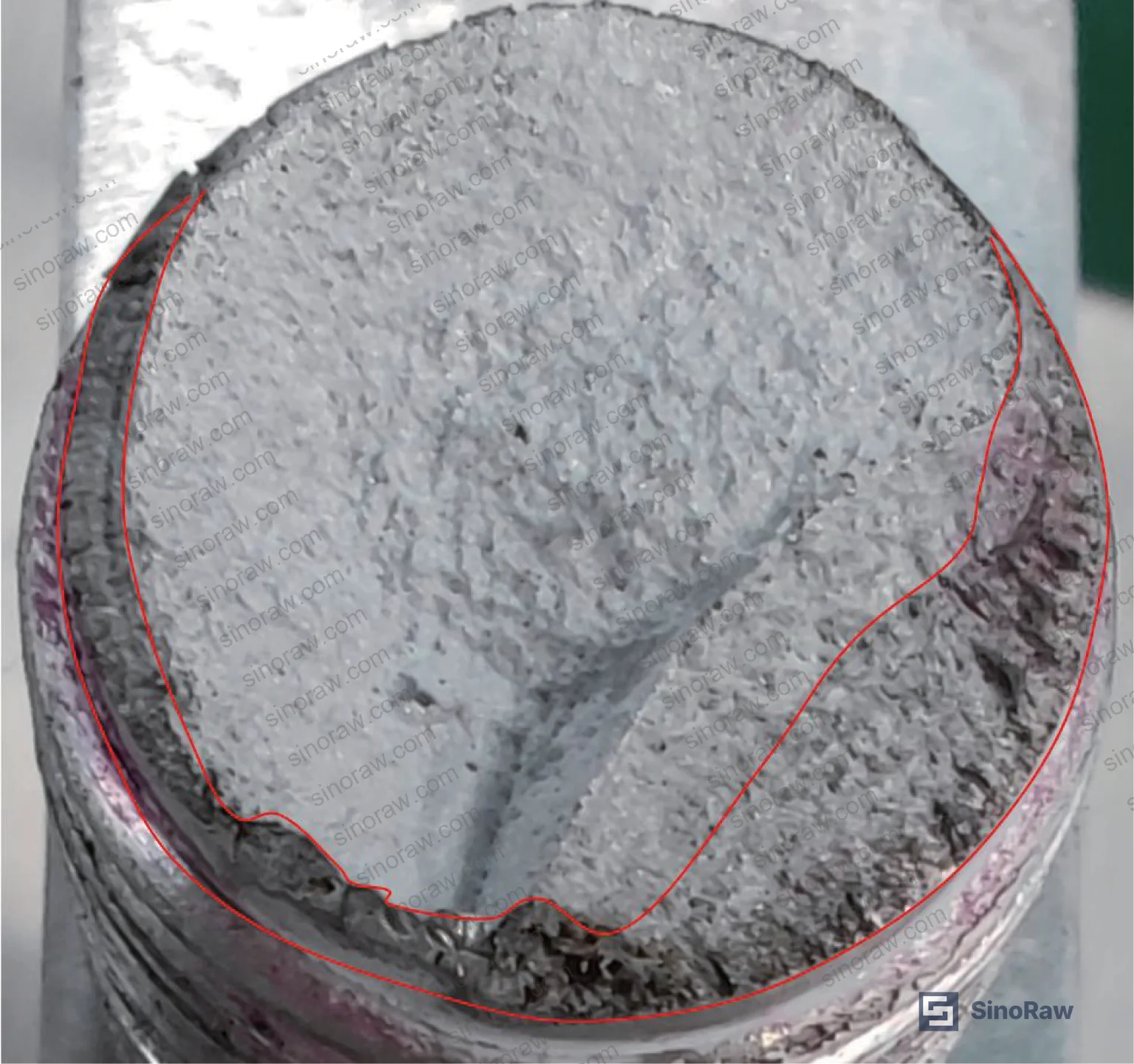
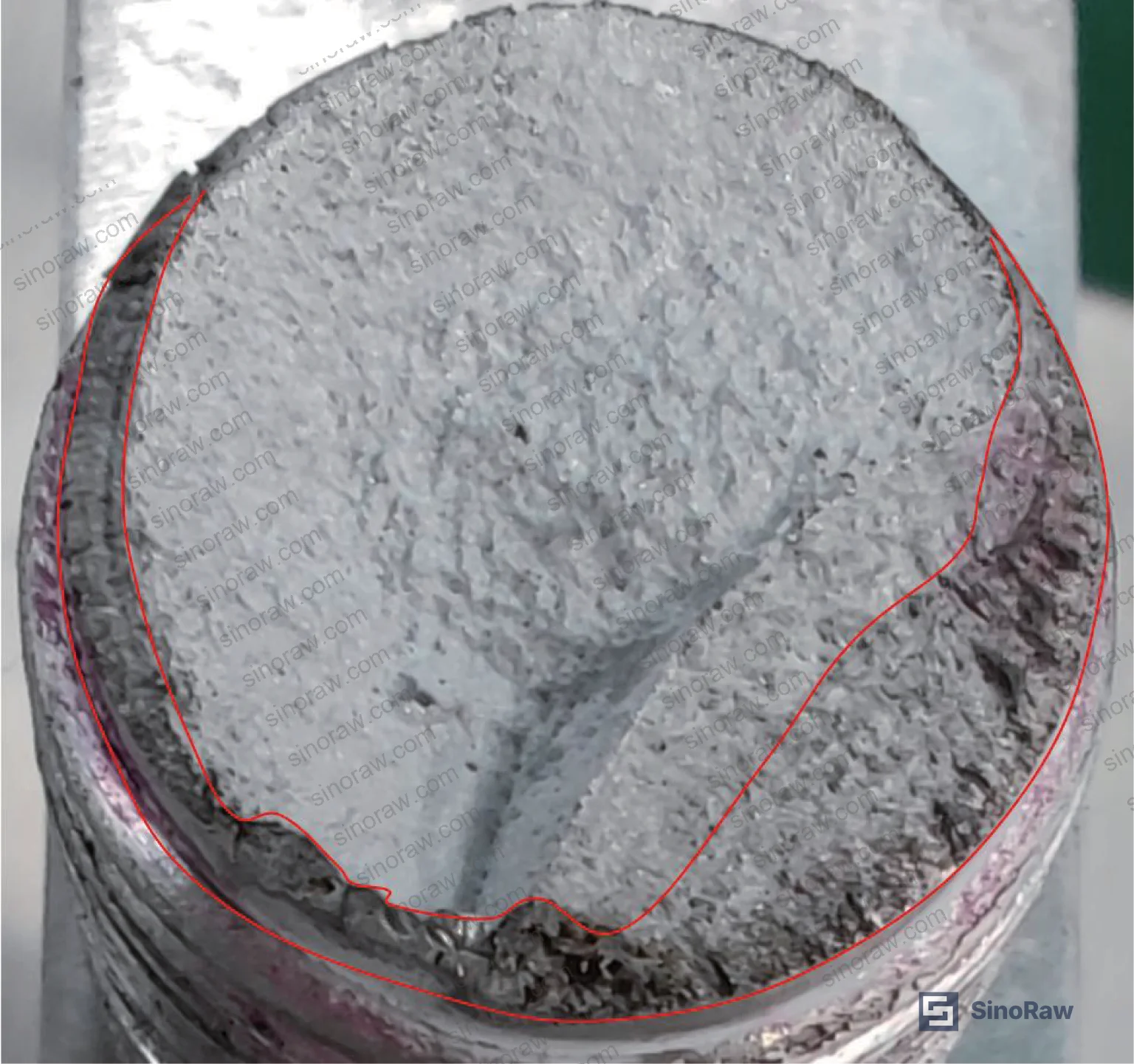
The fracture surface of Phase C told the full story macroscopically: roughly half the cross-sectional area showed a smooth, compressed appearance — classic fatigue crack propagation zone — while the other half showed the rough, fibrous texture of ductile overload fracture. This is the textbook beach-mark pattern of fatigue-dominated failure.
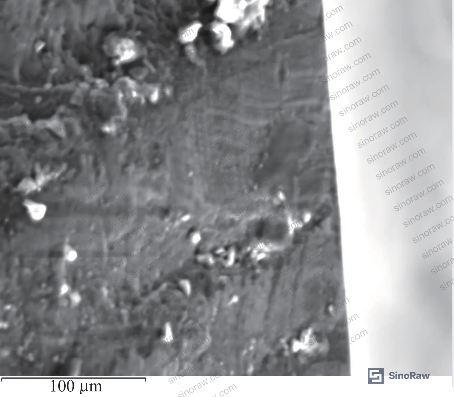
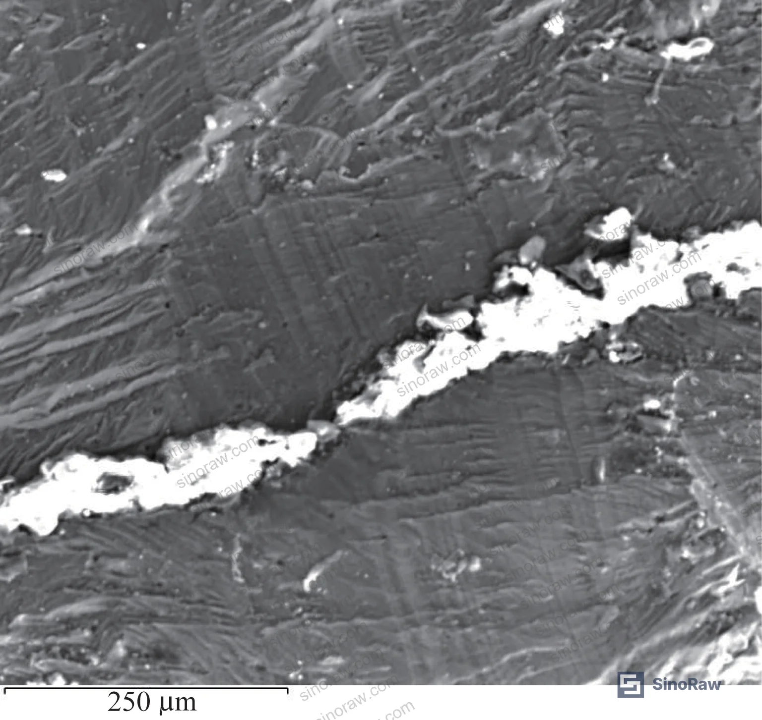
Microscopically, both Phase B and Phase C fracture surfaces showed fatigue striations (conchoidal markings) in the crack initiation zone — confirming cyclic crack growth prior to final overload fracture. Critically, no manufacturing defects were found at the fracture origin. This was not a casting flaw or a machining nick. The geometry itself was the problem.
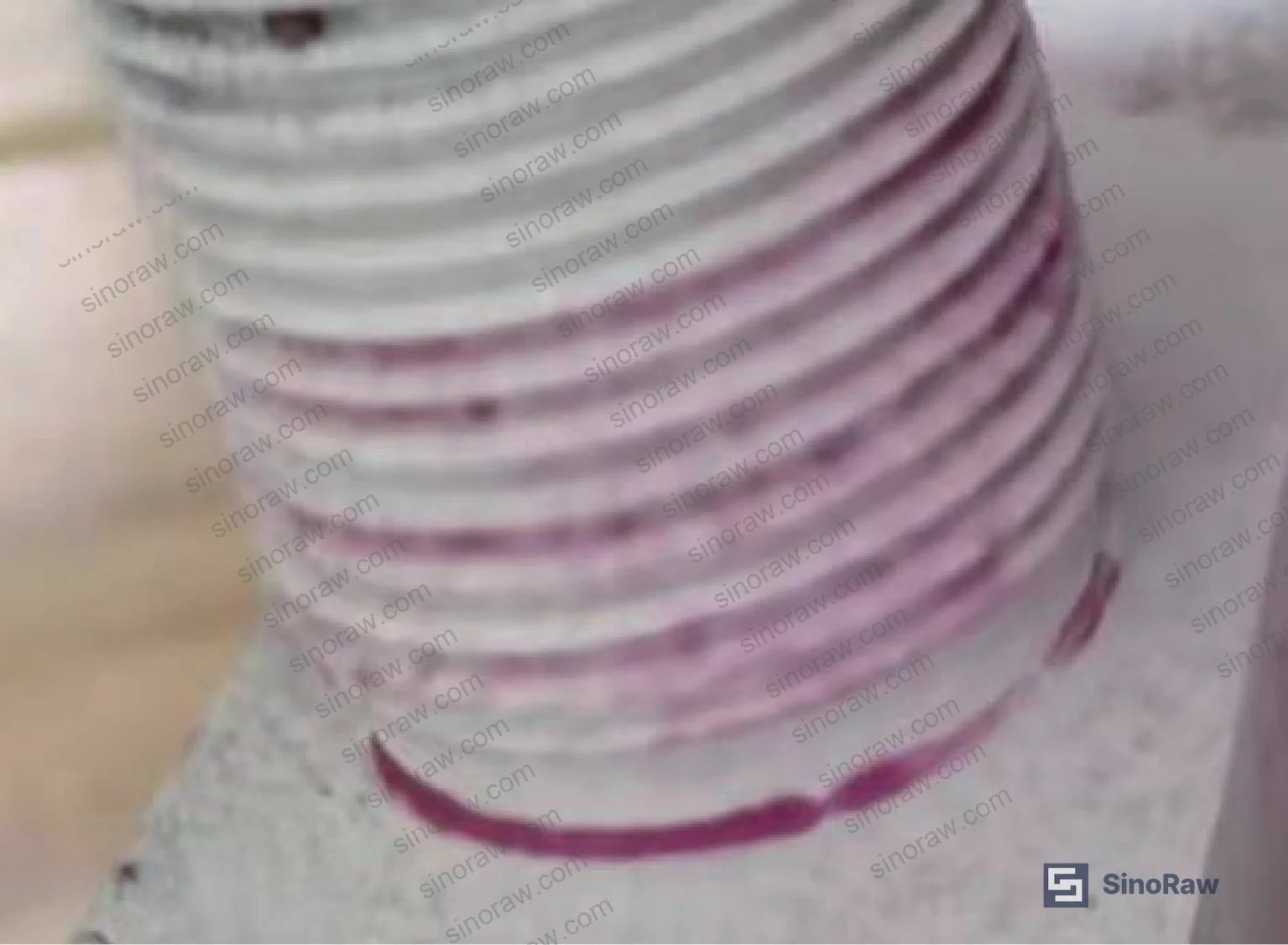
In supplier qualification work, we evaluated three terminals from the same batch and found all three had pre-existing fatigue cracks before any laboratory load was applied. Phase A showed penetrant infiltration less than 1 mm deep; Phase B showed red dye extending to significant depth — indicating a crack that had already been propagating in service. That’s a three-of-three failure rate on a fresh installation under 100 days old.
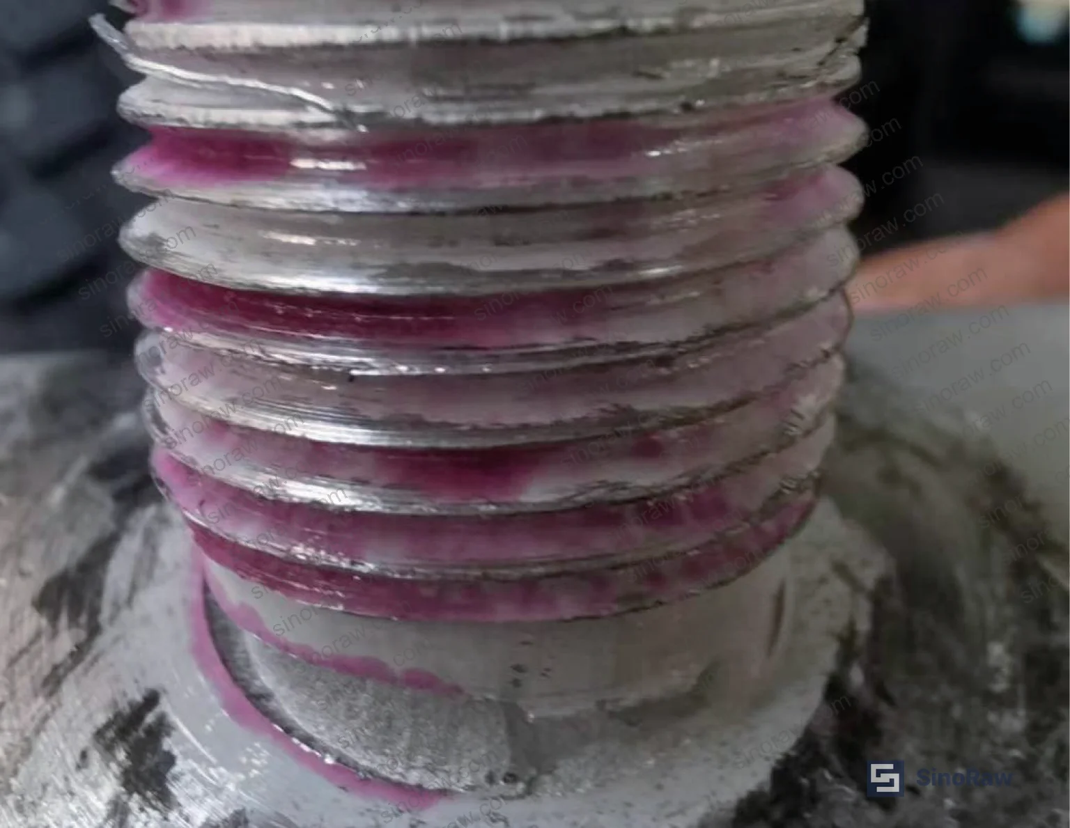
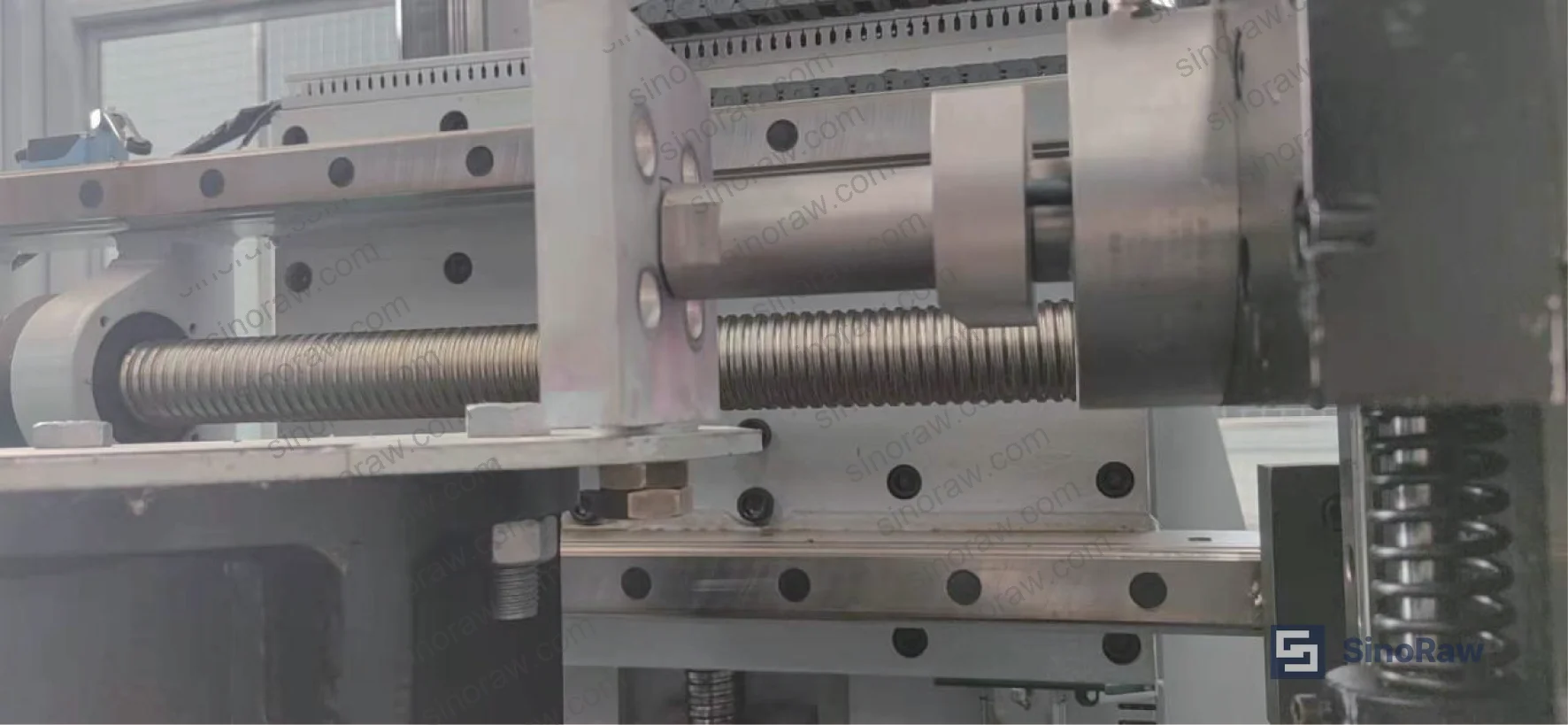
The bending tests confirmed both A-phase and B-phase terminals met the static design requirement of ≥3 kN horizontal resistance (Phase A failed at 9.92 kN, Phase B at 11.62 kN). This is exactly the trap: static test compliance, fatigue test failure. A terminal can pass every static load test in your incoming inspection protocol and still be on its way to a fatigue fracture the moment it goes into a vibrating installation.
Pre-stress, Installation Torque Variance, and the Compounding Effect #
Two installation factors compounded the fatigue problem significantly. First, the conductor connected to the failed terminal was misaligned by 150 mm from its natural free position when the terminal was installed. This means the terminal was operating under a constant horizontal pre-stress from the moment it was bolted up — before any service vibration was added.
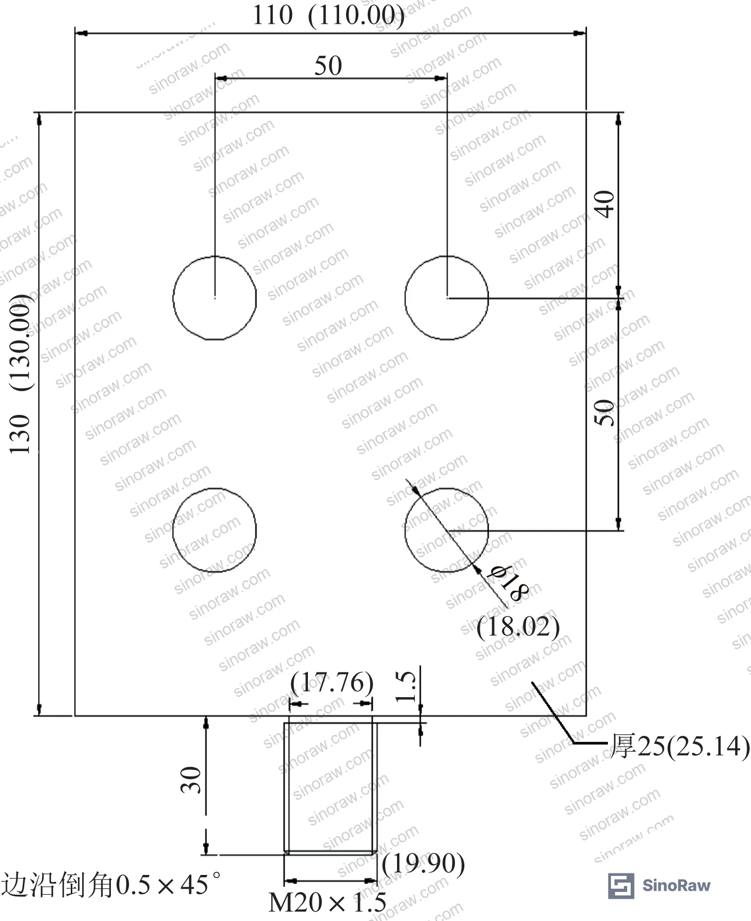
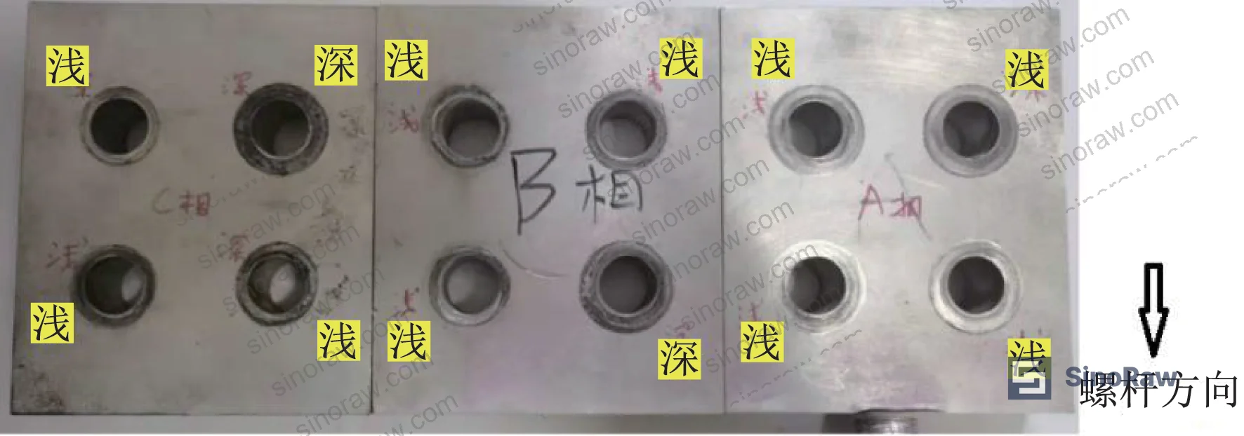
Second, visual examination of the bolt hole areas on the terminal mounting plate showed asymmetric extrusion marks around the four fastener holes. The four bolts were not torqued uniformly. Uneven fastener preload creates a moment across the terminal base, converting what should be pure compression into a combination of compression and bending — the worst loading scenario for fatigue initiation at a geometric stress concentration.
Neither of these conditions would show up on incoming inspection. Both are installation-side contributors. This matters for your supplier conversations: design robustness needs to account for realistic installation variance, not ideal installation conditions.
Most procurement teams don’t realize that vibration-induced fatigue specifications for substation hardware have historically lagged behind the actual operating conditions seen in high-frequency converter station environments. Converter stations impose vibration profiles that traditional substation fitting standards were never designed around — and current industry practice is still catching up on this gap.
Redesigned Terminal: Quantified Improvement in Fatigue Life #
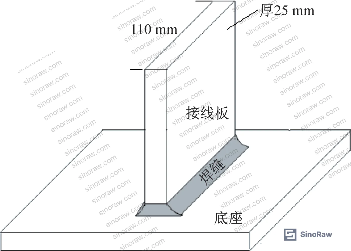
The corrective design change is instructive because it gives concrete, quantified targets for specifying improved components.
The redesigned terminal geometry increased the bending section modulus to 11,458 mm³ at the stud root. At this cross-section value, the terminal can sustain approximately 359 kg (3,520 N) of horizontal load while withstanding 1×10⁹ fatigue cycles — equivalent to approximately 16 years of service at the same 1.86 Hz vibration frequency.
That’s a 20× improvement in fatigue-rated horizontal load capacity (18 kg → 359 kg) from a geometry change alone, with no alloy upgrade required. This is the clearest argument for including bending section modulus as a mandatory specification parameter rather than relying solely on tensile strength and alloy grade.
Practical Guidance for Buyers #
If your procurement specification for aluminum electrical terminals — or any vibration-exposed precision fasteners and clamping hardware — is built exclusively around tensile strength, alloy grade, and static load ratings, you have a gap that this failure mode exploits directly.
The minimum additions to any technical specification for terminals used in vibrating installations are: (1) required bending section modulus at the stress concentration point, (2) fatigue-rated load capacity stated at a specific cycle count (at minimum 10⁷, preferably 10⁹), and (3) dye penetrant inspection of the stud root transition on incoming sample lots — not just dimensional checks.
Incoming spectroscopic verification against the specified alloy grade should be treated as mandatory, not optional. Certificate-only alloy acceptance is how you get 6063 delivered against a 6061 spec.
On the installation side, conductor routing alignment tolerance and fastener torque uniformity specifications should be included in your installation procedure documentation, because pre-stress and asymmetric bolt load are force multipliers on whatever fatigue margin your terminal design provides.
At sinoraw.com, we help overseas procurement engineers identify and pre-qualify Chinese manufacturers of electrical hardware and industrial components — connecting you with suppliers who can provide the fatigue analysis documentation and alloy verification data this application demands. Verifying these capabilities before issuing your RFQ is exactly what we support.
Compliance documentation should also address REACH Regulation (EC) No 1907/2006 for any aluminum alloy hardware entering European supply chains, particularly regarding alloying element declarations.
Need help identifying qualified suppliers for fatigue-rated aluminum electrical terminals? Talk to our sourcing team →
Supplier Qualification Questions #
- What is the bending section modulus (in mm³) of your terminal at the stud-to-baseplate transition, and can you provide the design calculation or FEA report confirming it meets ≥11,458 mm³ for vibration-exposed applications?
- What is the maximum horizontal load your terminal can sustain at 1×10⁷ fatigue cycles, and at what cycle count was fatigue-rated load capacity determined — does it exceed 18 kg at 2×10⁷ cycles under 6061-T6 material properties?
- Can you provide incoming material spectroscopic verification records confirming Mg content within 0.8–1.2% and Cu content within 0.15–0.4% per GB/T 3190-2020 for every production batch, and what is your procedure when a batch fails alloy verification?
- Do you perform dye penetrant inspection on the stud root radius area as part of your production or outgoing QC protocol, and what is your accept/reject criterion for surface crack indications at that location?
- What fastener torque specification do you provide for terminal mounting, and has the design been validated under asymmetric bolt preload conditions representing realistic field installation variance?
Sourcing Checklist #
- ☐ Alloy grade verified by optical emission spectroscopy against GB/T 3190-2020 — Mg 0.8–1.2%, Cu 0.15–0.4% for specified 6061 — not accepted on certificate alone
- ☐ Bending section modulus at stud root documented at ≥11,458 mm³ or equivalent fatigue-safe geometry per application vibration frequency
- ☐ Fatigue-rated horizontal load capacity stated at ≥1×10⁷ cycles — minimum threshold 18 kg; improved design target ≥359 kg at 1×10⁹ cycles
- ☐ Static bending-to-fracture test result ≥3 kN horizontal load per design specification, tested at the 4-bolt geometric center loading point
- ☐ Dye penetrant inspection (per supplier QC procedure) of stud-to-baseplate transition area — no surface crack indications accepted on outgoing sample lots
- ☐ Tensile strength minimum confirmed ≥260 MPa for 6061-T6 per BS EN 755-2:2008 (or equivalent) — not less than the 6063 baseline of ≥215 MPa
- ☐ Supplier can provide fracture surface analysis methodology (macro + SEM) as part of failure investigation capability for batch traceability
- ☐ ISO 2859-1:1999 sampling plan applied to incoming alloy verification — AQL defined and documented in purchase specification
Key Specifications Table #
| Parameter | Recommended Value | Verification Method |
|---|---|---|
| Alloy Grade (Specified) | 6061-T6 per GB/T 3190-2020 | Optical emission spectroscopy on each batch |
| Min. Tensile Strength | ≥260 MPa | Tensile test per BS EN 755-2:2008 |
| Bending Section Modulus at Stud Root | ≥11,458 mm³ | Design calculation or FEA + dimensional measurement |
| Fatigue-Rated Horizontal Load (10⁹ cycles) | ≥359 kg (3,520 N) | Fatigue analysis at operating frequency |
| Static Bending Failure Load | ≥3 kN (design min); tested ≥9.92 kN | 4-point bending test at bolt-hole geometric center |
| Surface Crack Indication (Penetrant) | None accepted at stud root radius | Dye penetrant inspection per production QC |
| Maximum Conductor Misalignment at Install | Minimize to eliminate pre-stress (reference: 150 mm misalignment = confirmed failure condition) | Installation procedure compliance check |
Can’t find a supplier meeting these specs? Submit your requirements and we’ll match you within 48 hours.
References #
Data source: Fatigue Fracture Analysis of Aluminum Alloy Terminals in High-Voltage Converter Station Transformers Under Cyclic Vibratory Loading, A. Xu et al., Engineering Failure Analysis, 2023
Frequently Asked Questions #
What is the difference between fatigue fracture and static overload fracture in aluminum terminals?
Fatigue fracture occurs when repeated cyclic loading — even at stress levels well below the material’s tensile strength — progressively propagates a crack until the remaining cross-section can no longer support even modest loads. In the case examined here, the terminal’s fracture surface showed approximately 50% smooth area (fatigue propagation zone) and 50% rough area (final ductile overload). Static overload fracture would show an entirely rough, fibrous surface with no beach marks or striations. The distinction matters because a terminal can pass every static acceptance test and still be failing by fatigue in service.
Why does alloy substitution (6063 instead of 6061) matter if both alloys meet minimum strength in many applications?
The 17% tensile strength deficit between 6063-T6 (≥215 MPa) and 6061-T6 (≥260 MPa) is the headline number, but the more important issue is that you received something other than what you specified. If a supplier substitutes alloy grade without disclosure on one terminal, the same substitution may appear in other components or future batches. The analysis here showed that even properly specified 6061 terminals developed fatigue cracks — so alloy substitution was a secondary issue, but the audit and control failure it represents is a primary concern.
How do I detect pre-existing fatigue cracks in incoming terminal samples?
Dye penetrant inspection is the practical method for surface crack detection at the stud-to-baseplate transition radius. In the case examined, Phase A showed penetrant infiltration less than 1 mm at the stud root; Phase B showed penetrant extending to significant depth prior to any laboratory loading. This is a low-cost inspection technique that can be applied to sample lots under an ISO 2859-1 sampling plan. SEM fractography is reserved for failure investigation rather than routine incoming inspection.
Does a higher static bending load rating guarantee better fatigue performance?
No — and this is one of the most common and costly misunderstandings in specifying these components. Phase A and Phase B terminals both passed the static design requirement (≥3 kN) with test results of 9.92 kN and 11.62 kN respectively, yet both already had fatigue cracks before the static test was even conducted. Fatigue performance is governed by the bending section modulus and the stress concentration geometry at the critical cross-section, not by how high the static failure load is.
What vibration frequency threshold should trigger a fatigue-specific design review for electrical terminals?
Any installation with continuous vibration at or above approximately 1 Hz should prompt a fatigue analysis, since even low-amplitude oscillation at that frequency accumulates to over 3×10⁷ cycles per year. The converter station installation in this case operated at 1.86 Hz — unremarkable as a vibration frequency — but accumulated 1.6×10⁷ cycles in just 100 days of operation. Suppliers should be asked specifically whether their terminal designs have been validated under the vibration frequency present in the target installation, not just under static load conditions.
Published by sinoraw.com Technical Team | Request a sourcing quote


