

TL;DR #
Under external pipeline loads of 46,750 N, a NPS3-Class150 metal-seated globe valve with the baseline body configuration failed to form a complete sealing ring — contact pressure dropped to zero across the 55°–115° circumferential zone, creating a measurable leakage path. Buyers specifying metal-seated globe valves for power plant, petrochemical, or marine service must verify that the valve body geometry has been engineered to resist external load deformation, not just internal pressure. Before issuing any RFQ, require suppliers to provide FEA-validated preload specifications and rib plate configuration data demonstrating full-contact sealing ring formation under the actual pipeline loads in your system.
Overview #
Most procurement teams evaluate globe valve sealing performance purely against internal pressure ratings — and that’s where a lot of expensive leakage problems start. The research underpinning this guide was conducted at a valve manufacturer with close collaboration from an engineering university, using finite element simulation on a NPS3-Class150 metal hard-sealed globe valve prototype. The simulation applied three simultaneous load conditions — 3 MPa internal fluid pressure, 10,000 N plug preload, and 46,750 N external system load — with quantified leakage length and leakage width as the primary sealing performance indicators.
What makes this analysis practically valuable is that it isolates the contribution of three structural variables — rib plate width, middle body geometry, and preload force — on seal face contact behavior. The results are specific enough to directly inform supplier qualification and product acceptance criteria.
For buyers in power generation, offshore, or chemical processing, the baseline finding is sobering: an otherwise nominally compliant valve body can produce zero contact pressure across nearly 33% of its circumferential sealing surface when external pipeline loads are applied. That is not a borderline failure. It is a full internal leak path.
Industry standards such as IEC 62619:2022 and valve-specific codes increasingly require sealing performance validation under combined load scenarios — yet a significant proportion of Chinese valve suppliers still test only under internal pressure, with fixed outlet constraints and no external bending moment. Buyers importing for critical-service applications need to close that gap themselves.
How External Loads Cause Metal-Seated Globe Valve Seal Failure #
The sealing mechanism of a metal hard-seated globe valve depends on three non-negotiable criteria being satisfied simultaneously: a full-contact sealing ring (continuous circumferential contact with no gaps), effective sealing width (contact band of 1.5–2.5 mm minimum per design convention), and effective specific sealing pressure (contact pressure must exceed fluid pressure at all points).
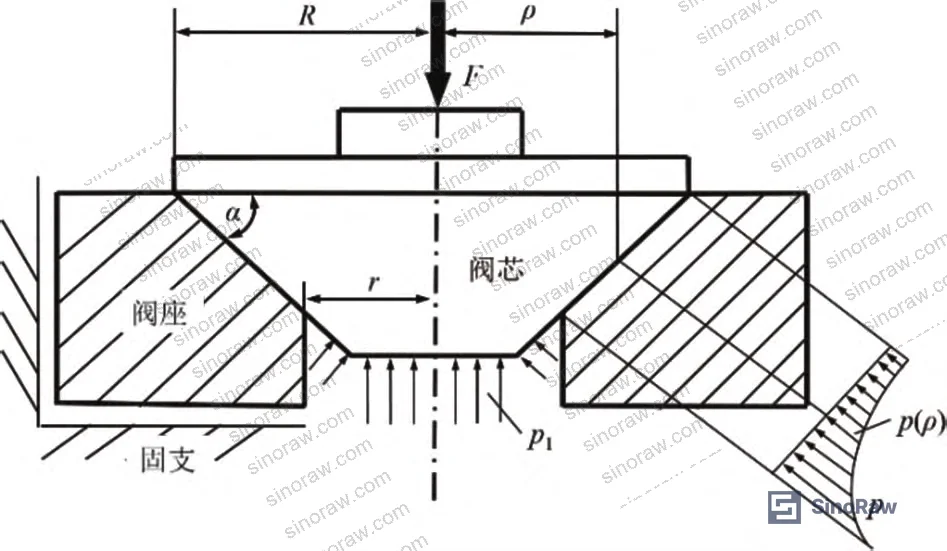
Under fixed-boundary conditions with internal pressure only, a properly designed cone-seat valve can satisfy all three. The contact pressure at radius ρ from the centerline is inversely proportional to that radius — meaning the inner edge of the sealing face sees higher specific pressure, which is favorable. The problem begins when the valve body deforms radially under external system loads.
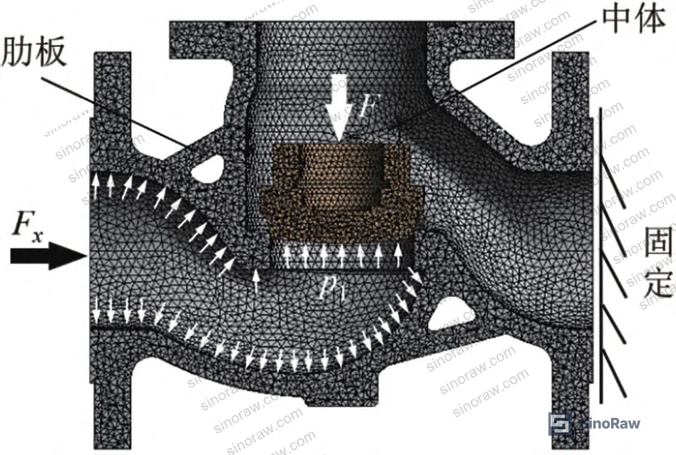
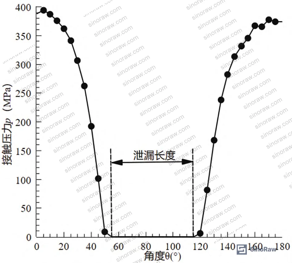
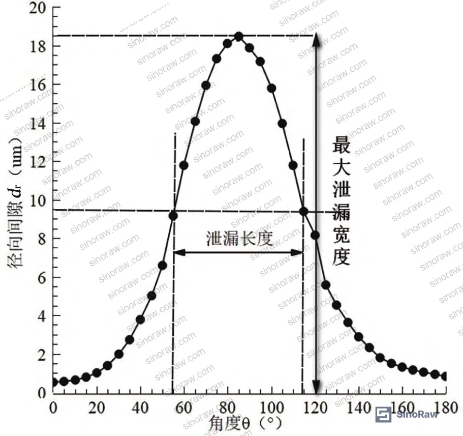
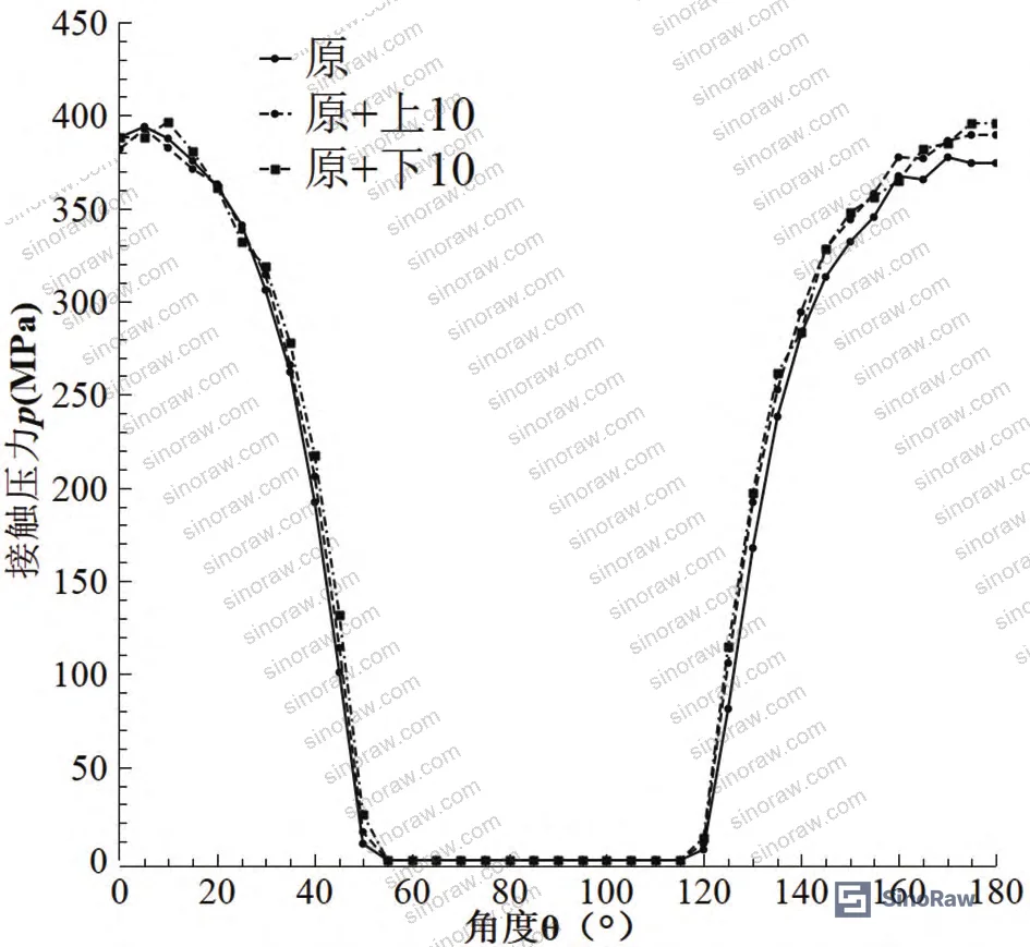
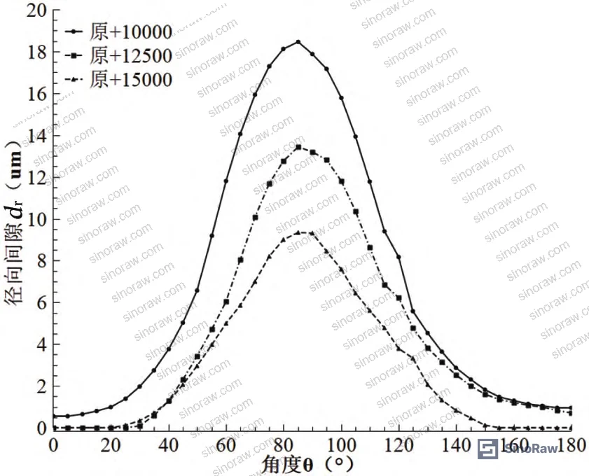
At the baseline configuration, simulations show that the sealing face splits into two distinct contact zones — 0°–55° and 115°–180° — while the 55°–115° zone shows zero contact pressure. Contact pressure at the active zones is well above the 3 MPa fluid pressure, but that provides no benefit where no contact exists. The circumferential gap peaks near 85°, generating the maximum leakage width. The result is a crescent-shaped leakage area with both a definable leakage length (the arc length of the non-contact zone) and a leakage width (the maximum radial gap across that zone).
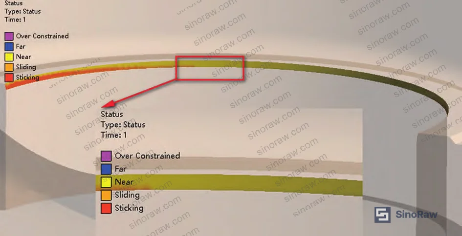
The sealing face material is Stellite 6 alloy, hard-faced onto the ASTM A216 WCB valve body base material. Surface hardness reaches 37–45 HRC and surface roughness Ra 0.4 μm after lapping — those are appropriate specifications. But good surface finish cannot compensate for structural deformation at the body level. This is the core finding that most buyers miss.
Per ASME VIII-1 UG44, the equivalent pressure load applied to the flange face incorporates axial forces, bending moments, and maximum allowable working pressure at design temperature. The external load Fx in this analysis was calculated from that formula and represents a realistic pipeline stress scenario — not an extreme case.
Structural Parameters That Control Sealing Performance Under External Load #
Three variables were systematically varied in the FEA study: rib plate width, middle body geometry, and plug preload force. Each has a distinct and separable effect on the leakage metrics.
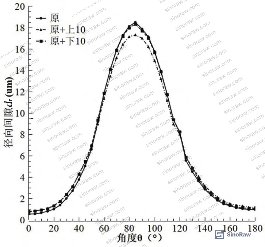
Rib plate width. Increasing rib plate width by 10 mm — either upward or downward from the baseline — reduces maximum leakage width. Leakage length remains essentially unchanged. Importantly, upward rib width increase is more effective at reducing leakage width than downward increase of the same magnitude. The mechanism is straightforward: wider ribs increase overall body stiffness, reducing radial deformation at the seat. This is a low-cost structural modification with a targeted effect on leakage width.
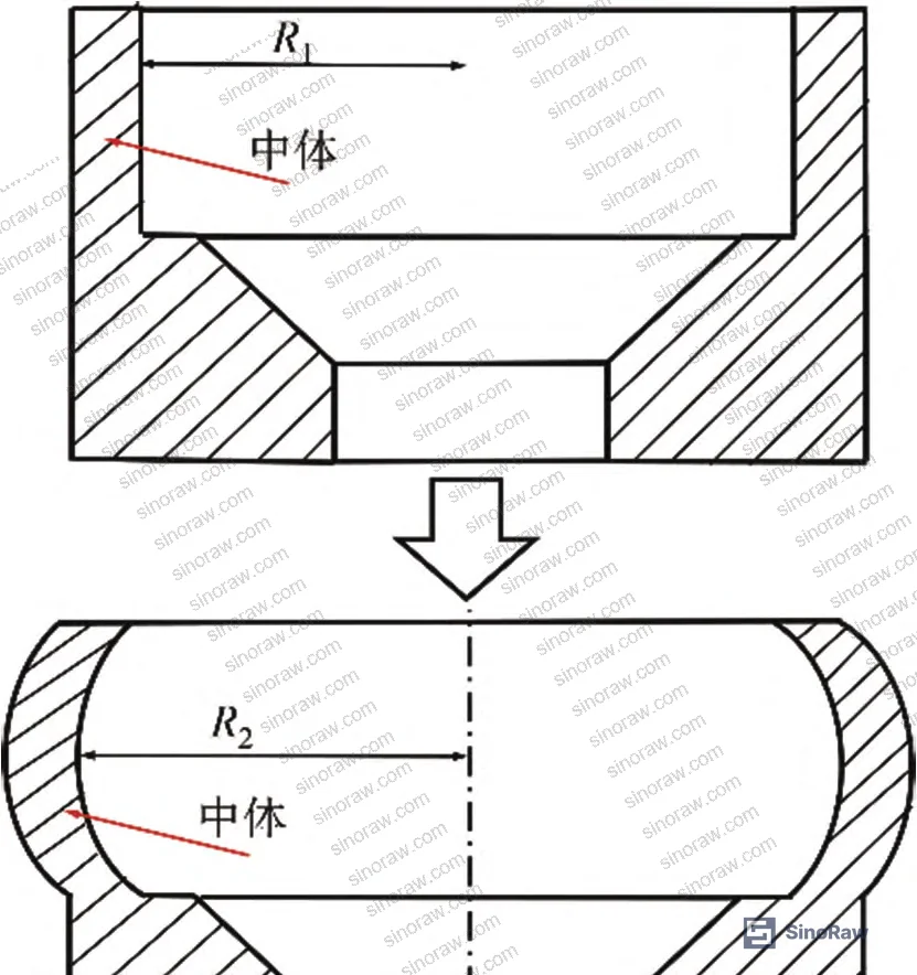
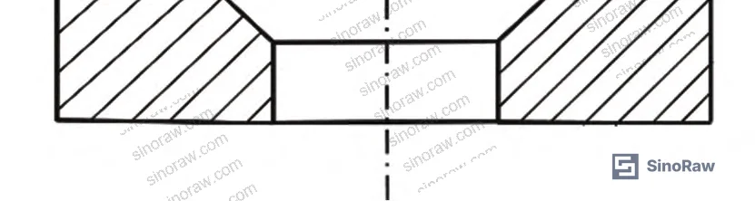
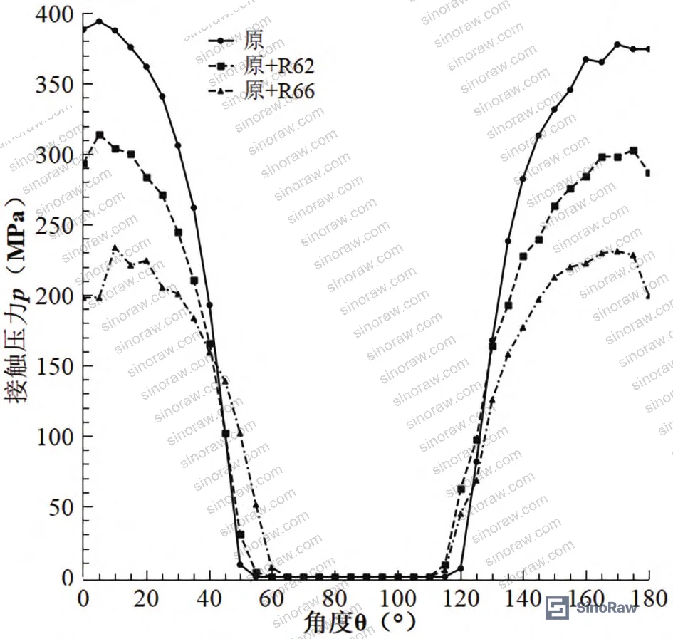
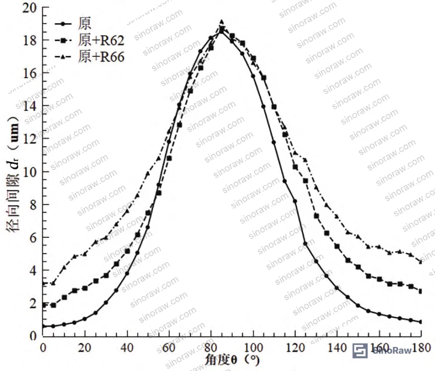
Middle body geometry. Converting the middle body from a straight cylindrical form to a spherical configuration (tested at R=62 mm and R=66 mm) primarily reduces leakage length by lowering contact pressure in previously non-contact zones. Maximum radial deformation — and therefore maximum leakage width — is not significantly affected by this change. The spherical section has a higher section modulus against bending than an equivalent cylindrical section of the same wall thickness, which explains the improved resistance to the bending moment component of the external load.
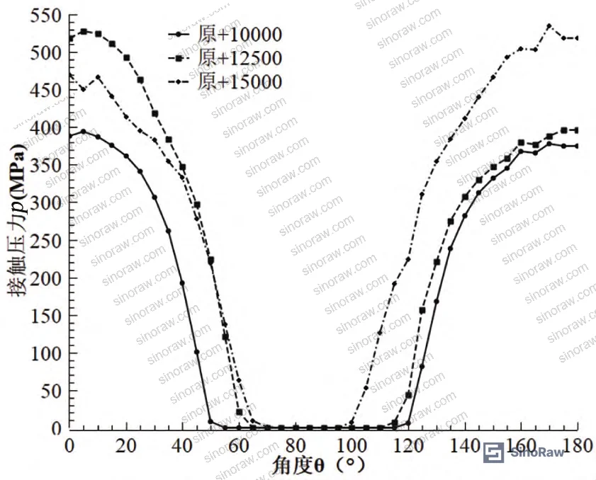
Preload force. This is the most powerful single variable. Increasing preload from the baseline 10,000 N to 12,500 N and then to 15,000 N progressively reduces both leakage length and leakage width. At 15,000 N, combined with optimized rib and middle body geometry, the seal face achieves full circumferential contact — the full-contact sealing ring criterion is met. Maximum seal face stress at this optimized configuration is 325.45 MPa, which is well below the yield strength of Stellite 6 alloy (541 MPa). No plastic deformation of the sealing surface occurs.
Honestly, most buyers over-specify sealing surface hardness and under-specify preload force requirements. A Stellite-faced seat at 40 HRC means nothing if the actuator torque specification doesn’t deliver sufficient plug preload to maintain full contact under pipeline bending loads. That’s a procurement error I see repeatedly in RFQs for power station service.
The comparison below summarizes the differential effect of each structural modification:
| Design Variable | Primary Effect | Secondary Effect | Leakage Metric Affected |
|---|---|---|---|
| Rib plate width +10 mm (upward) | Reduces maximum leakage width | Minor effect on leakage length | Leakage width (primary) |
| Spherical middle body (R=62–66 mm) | Reduces leakage length | Negligible effect on leakage width | Leakage length (primary) |
| Preload increase 10,000 → 15,000 N | Reduces both leakage length and width significantly | Raises seal face contact pressure | Both leakage dimensions |
| Combined optimization (all three) | Full-contact sealing ring achieved | Max stress 325.45 MPa vs. 541 MPa yield | Complete seal — zero radial gap at base |
Optimized Configuration: What Full Sealing Actually Looks Like #
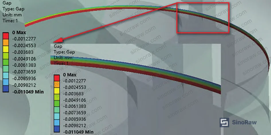
The final optimized configuration combines spherical middle body geometry, upward-widened rib plates, and 15,000 N preload. Under the full load condition — 3 MPa internal pressure plus 46,750 N external load — the seal face achieves:
- Complete circumferential contact (full-contact sealing ring criterion satisfied)
- Zero radial gap at the base of the sealing face (effective sealing width criterion satisfied)
- Contact pressure exceeding fluid pressure at all circumferential positions (effective specific sealing pressure criterion satisfied)
- Maximum seal face stress of 325.45 MPa — a safety margin of over 40% against Stellite 6 yield strength of 541 MPa
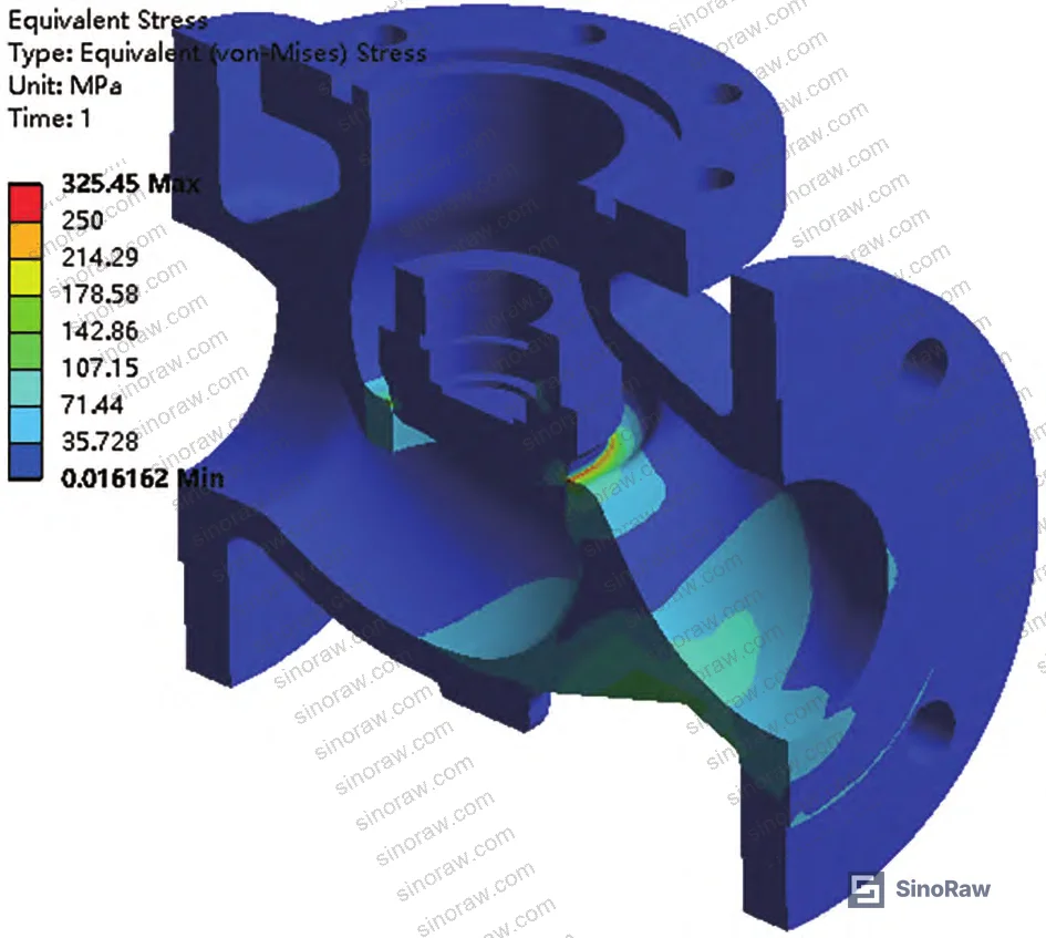
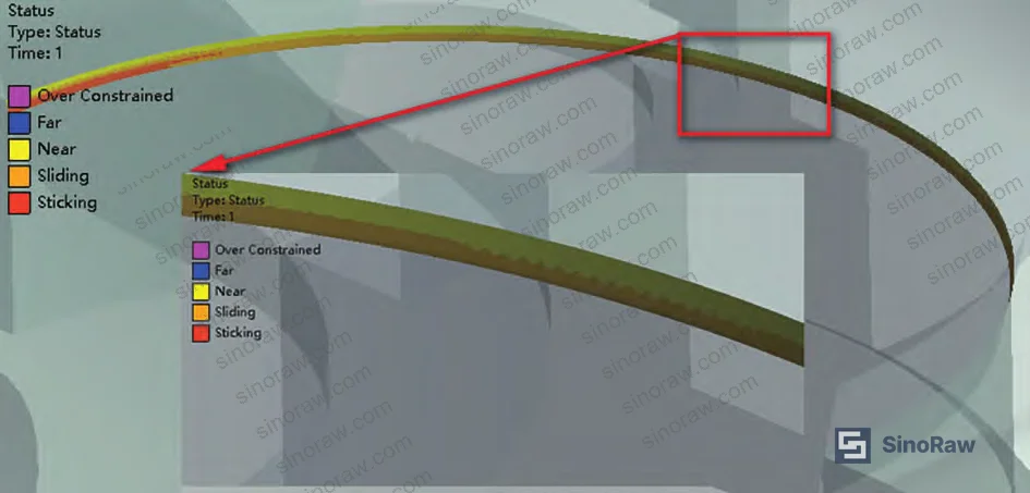
The Stellite 6 alloy hard-facing specification remains constant throughout: 2 mm minimum deposition thickness, 37–45 HRC surface hardness, Ra 0.4 μm surface finish after lapping. These are the standard interface specifications. What changes is the body structure behind the seat.
One important caveat on preload: increasing preload beyond the validated range risks excessive plastic deformation of the sealing surfaces and increases actuator sizing requirements and cost. The 15,000 N figure in this study is the optimized value, not a general recommendation to maximize preload. Suppliers should be able to show you the preload optimization curve, not just a single nominal value.
Most procurement teams don’t realize that the standard valve testing protocols for small-bore globe valves — particularly below NPS4 — typically do not include external load testing in their mandatory test matrix. The external load requirement appears in standards for axial-flow valves and ball valves, but NPS3 globe valves often fall outside that scope. That gap in the testing framework means an externally loaded application is entirely relying on the supplier’s internal design validation, which may or may not exist.
For flanged connections subject to ASME VIII-1 UG44 loading, the equivalent external load Fx is calculated from actual pipeline axial forces, bending moments, and design pressure. In chemical and power plant piping, it is routine for Fx to approach or exceed 40,000 N on a 3-inch line. Specifying a valve without asking whether it has been validated at that load level is the kind of procurement gap that generates maintenance calls eighteen months into service.
Practical Guidance for Buyers #
If you are sourcing metal-seated globe valves for power plant, petrochemical, or marine piping systems — especially NPS3 and similar small-bore critical-service applications — the sealing performance criteria you need to verify go beyond surface finish and hardness. You need to know whether the valve body structure has been designed and validated to resist the external loads that the piping system will actually impose.
The three structural factors that matter most are preload specification, rib plate geometry, and middle body form. A supplier who cannot tell you the design preload force for their plug actuator, or who has not evaluated their seat contact behavior under external bending loads, is not qualified for Class 150 critical-service applications regardless of what their certificate says. At sinoraw.com, we work with overseas procurement engineers and technical buyers to identify and pre-screen Chinese valve manufacturers who have done this kind of structural validation work — so you can request the right technical documentation before committing to a trial order.
For compliance reference, buyers should also consult ISO 12405-4 and the broader family of industrial valve standards to understand how combined-load scenarios are addressed in relevant test specifications. Sealing performance under external load is a defined engineering requirement, not an optional quality add-on.
Need help identifying qualified suppliers for metal-seated globe valves with FEA-validated external load sealing performance? Talk to our sourcing team →
Supplier Qualification Questions #
- What is the design preload force (in Newtons) for the plug in your NPS3-Class150 metal-seated globe valve, and can you confirm that this preload was validated to maintain full circumferential contact under an external lateral load of at least 46,750 N per ASME VIII-1 UG44 equivalent load calculation?
- Has the valve body been FEA-simulated under combined loading conditions (internal pressure ≥3 MPa plus external bending load)? If so, what were the resulting leakage length and leakage width values at the baseline configuration, and what structural modifications were implemented to reduce them?
- What is the rib plate width specification in your valve body design, and can you demonstrate — through simulation or test data — that this width is sufficient to keep maximum leakage width within acceptable limits under full external load?
- Is the middle body of your valve designed as a spherical or cylindrical section? If spherical, what is the sphere radius, and what improvement in leakage length versus a cylindrical middle body has been measured or simulated for your design?
- What is the maximum seal face stress at your optimized preload and external load condition, and how does this compare to the yield strength of your Stellite 6 or equivalent hard-facing alloy (target: seal face stress ≤60% of alloy yield strength, i.e., below approximately 325 MPa for Stellite 6 at 541 MPa yield)?
Sourcing Checklist #
- ☐ Valve body material confirmed as ASTM A216 WCB or equivalent, with seal face hard-facing minimum 2 mm Stellite 6 deposition thickness
- ☐ Seal face surface hardness verified at 37–45 HRC via Rockwell test on production samples
- ☐ Seal face surface roughness Ra ≤0.4 μm confirmed via profilometer measurement after lapping
- ☐ Supplier has provided FEA results showing full circumferential contact ring formation under combined load (internal pressure + external load ≥46,750 N equivalent)
- ☐ Design plug preload force documented and confirmed at ≥15,000 N for external-load-rated configurations
- ☐ Maximum seal face stress under full load confirmed below 60% of Stellite 6 yield strength (i.e., ≤325 MPa)
- ☐ Effective contact band width at seal face confirmed within 1.5–2.5 mm per design specification
- ☐ External load calculation basis documented per ASME VIII-1 UG44 or equivalent standard, with Fx calculation traceable to actual pipeline parameters
Key Specifications Table #
| Parameter | Recommended Value | Verification Method |
|---|---|---|
| Plug preload force (external-load-rated service) | ≥15,000 N | Actuator torque calculation + FEA contact analysis |
| Stellite 6 hard-facing thickness on seat | ≥2 mm | Cross-section metallographic measurement |
| Seal face surface hardness | 37–45 HRC | Rockwell hardness test on production coupon |
| Seal face surface roughness | Ra ≤0.4 μm | Contact profilometry after lapping |
| Effective sealing contact band width | 1.5–2.5 mm | Contact marking / blue-ink impression test |
| Maximum seal face stress under combined load | ≤325 MPa (≤60% of 541 MPa Stellite 6 yield) | FEA stress contour at design load condition |
| External equivalent load Fx (design input) | Calculated per ASME VIII-1 UG44 | Engineering calculation record, traceable to piping loads |
| Middle body sphere radius (if spherical design) | R = 62–66 mm for NPS3 range | Dimensional inspection / drawing verification |
Can’t find a supplier meeting these specs? Submit your requirements and we’ll match you within 48 hours.
References #
Data source: Structural Optimization of Metal-Seated Globe Valves for Sealing Performance Under Combined External and Internal Loads, W.-G. He et al., Journal of Pressure Vessel Technology, 2024
Frequently Asked Questions #
What is a “full-contact sealing ring” and why does it matter for procurement?
A full-contact sealing ring means the plug and seat surfaces maintain continuous, unbroken circumferential contact around the full 360° of the cone seal. If any arc of that contact ring is interrupted — as happens when external loads cause radial body deformation — fluid has an unobstructed path through the gap. In the baseline simulation, contact dropped to zero across a 60° arc (55°–115°), which is a complete internal leak path regardless of how high the contact pressure is in the remaining zones. This is the most fundamental sealing criterion, and it is the one most likely to be violated under external pipeline loading.
What external loads should I specify when sourcing globe valves for power plant or chemical plant service?
Use the ASME VIII-1 UG44 equivalent pressure approach to convert your actual pipeline axial forces and bending moments into an equivalent Fx load. For a 3-inch line in typical process piping, external lateral loads of 40,000–50,000 N are not unusual. Give that calculated Fx value to your supplier and ask them to confirm their valve has been validated at or above that level — either through FEA or physical testing. If they cannot respond to that question technically, that tells you what you need to know.
Does increasing preload force always improve sealing performance?
Up to a point, yes — but there is a real upper limit. Excessive preload causes plastic deformation of the Stellite sealing surface, which permanently alters the contact geometry and can accelerate wear. It also requires a larger, more expensive actuator. The optimized preload of 15,000 N in this study was selected because it achieves full sealing ring contact while keeping maximum seal face stress at 325.45 MPa — safely below the 541 MPa yield strength of Stellite 6. Buying a valve with a higher preload rating than your application requires is not conservative; it adds cost and wear risk.
Why do rib plate width and middle body geometry affect different leakage metrics?
Rib plate width primarily governs overall body stiffness, which controls the magnitude of radial deformation — hence its effect on leakage width (the radial gap dimension). Middle body geometry affects how the valve body distributes the bending moment from external loads; a spherical section has a higher section modulus than a cylinder of equal wall thickness, so it resists bending more effectively and reduces the arc length over which contact is lost — the leakage length. Because these two mechanisms are independent, you need both optimized to achieve full sealing.
Are these findings relevant only to NPS3-Class150 valves, or do they apply more broadly?
The specific numeric thresholds — 46,750 N external load, 15,000 N preload, 325.45 MPa peak stress — are specific to NPS3-Class150 geometry. But the design principles apply directly to any metal-seated globe valve in external-load service: rib stiffness controls radial deformation, middle body bending stiffness controls leakage arc length, and preload is the most effective single variable for closing both leakage dimensions. For other sizes and pressure classes, the same FEA methodology should be applied with size-appropriate load inputs. For related sealing and fluid-control components in your system, see our Pump & Valve Seals and Fluid Control documentation categories.
Published by sinoraw.com Technical Team | Request a sourcing quote


