

TL;DR #
FEA simulation of NBR O-ring pneumatic seals across three cross-section diameters confirms that larger cross-sections deliver meaningfully wider sealing contact width — up to 1.474 mm versus 0.720 mm — without proportionally increasing Mises stress, giving you more sealing margin for the same groove footprint. For buyers specifying O-rings in pneumatic valve or brake actuator applications, this means cross-section diameter selection is a higher-leverage decision than most procurement specs acknowledge. Prioritize groove geometry data from your supplier and request FEA-backed compression rate validation before approving a new seal design.
Overview #
If you’re sourcing NBR O-rings for pneumatic actuators, brake valves, or any compressed-air control component, the performance gap between a well-specified seal and a loosely-specified one is not theoretical — it shows up as in-service leakage, premature elastomer fatigue, and expensive field returns. Research conducted at a Chinese rail engineering institute — using axisymmetric finite element models validated against physical uniaxial stress-strain data for NBR at 23 °C — provides some of the most granular contact mechanics data currently available for pneumatic-duty O-ring design. The study modeled a 25 mm bore piston seal under 950 kPa working pressure across multiple cross-section diameters and compression rates, covering pre-compression, pressurization, and active piston stroke phases. That test pressure, 950 kPa, is the standard header pressure in Chinese railway brake systems and sits comfortably within the operating range of most industrial pneumatic circuits.
The material model used was a 3rd-order Ogden hyperelastic formulation — not the simpler Mooney-Rivlin approach — chosen specifically for its accuracy at large strains. Poisson’s ratio was set to 0.49 to reflect NBR’s near-incompressibility. The FEA mesh comprised 16,095 nodes and 8,101 elements, using CAX4RH and CAX3H hybrid axisymmetric elements suited to rubber contact problems. This is a technically credible methodology, not a back-of-envelope estimate.
For buyers working through pneumatic Sealing & Thermal components, the key takeaway is that contact width and pressure transfer coefficient — not just max contact stress — are the metrics that separate a reliable seal from one that will degrade early.
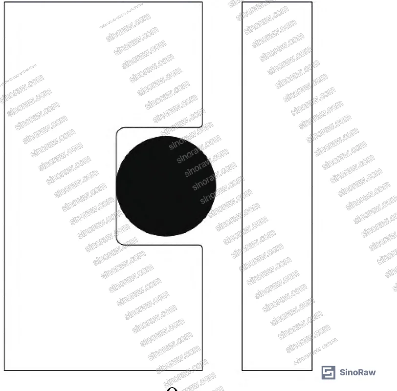
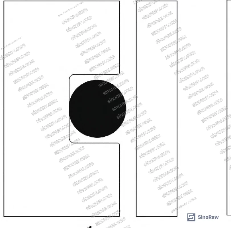
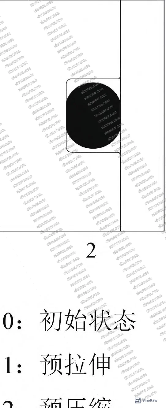
Cross-Section Diameter: The O-Ring Parameter That Actually Drives Pneumatic Seal Reliability #
Most procurement engineers focus on bore size and compression rate when specifying O-rings. Cross-section diameter gets treated as a secondary parameter — whatever fits the groove. That’s a mistake, and the data is clear about it.
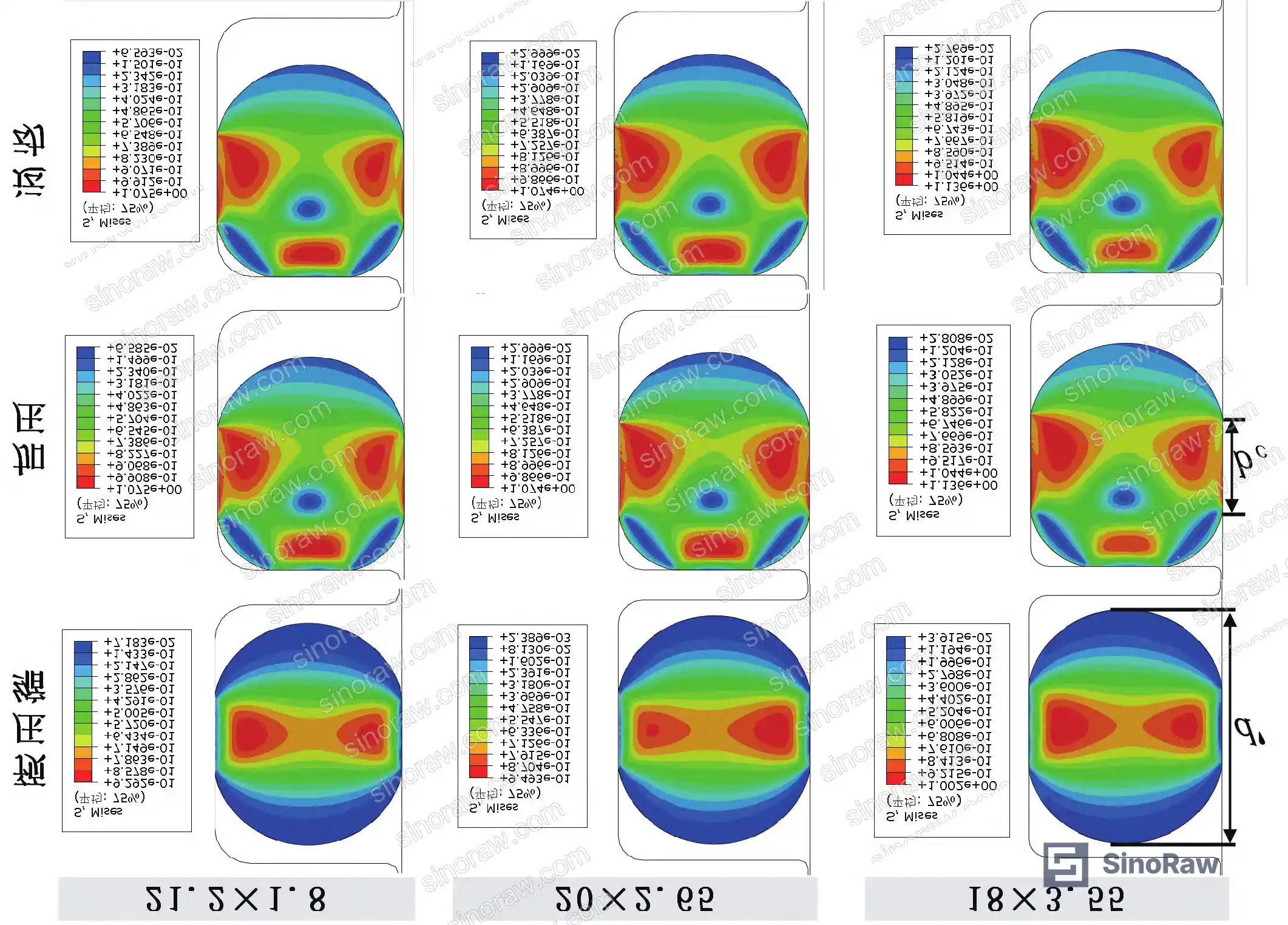
Three NBR O-ring sizes were evaluated for the same 25 mm bore piston: ϕ21.2 mm × 1.8 mm, ϕ20 mm × 2.65 mm, and ϕ18 mm × 3.55 mm. All three were run at an identical compression rate of 10.03% under 950 kPa media pressure.
The Mises stress and maximum contact stress values converged closely across all three — meaning the larger cross-section doesn’t cost you in stress loading. But contact width scaled dramatically:
| O-Ring Specification | Max Mises Stress (MPa) | Max Contact Stress (MPa) | Contact Width (mm) | Pressure Transfer Coefficient K |
|---|---|---|---|---|
| ϕ21.2 mm × 1.8 mm | 1.075 | 2.143 | 0.720 | 0.929 |
| ϕ20 mm × 2.65 mm | 1.074 | 2.147 | 1.094 | 0.866 |
| ϕ18 mm × 3.55 mm | 1.136 | 2.164 | 1.474 | 0.873 |
The 3.55 mm cross-section delivers 2.05× the contact width of the 1.8 mm version, with only a 5.7% increase in Mises stress. In pneumatic sealing — where lubrication is poor compared to hydraulic duty — that wider contact band is your primary buffer against leakage during piston eccentricity and vibration.
The pressure transfer coefficient K, which quantifies self-sealing capability (how effectively working pressure augments the contact stress), is slightly higher for the smallest cross-section (K = 0.929 vs. 0.866–0.873 for larger sections). Honestly, the difference is small enough that it shouldn’t drive your selection. In practice, the contact width advantage of the larger cross-section outweighs the marginal self-sealing efficiency of the smaller one — especially under dynamic conditions where the seal is not perfectly centered.
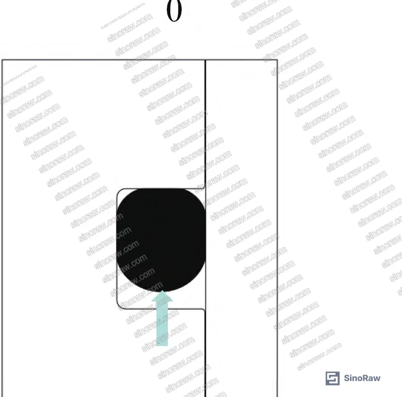
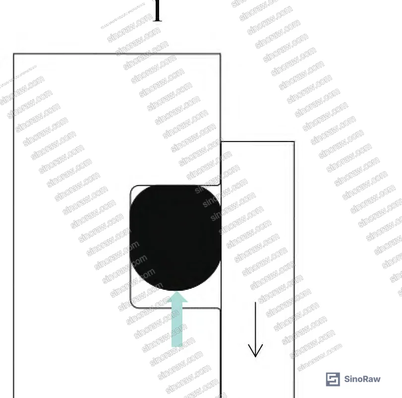

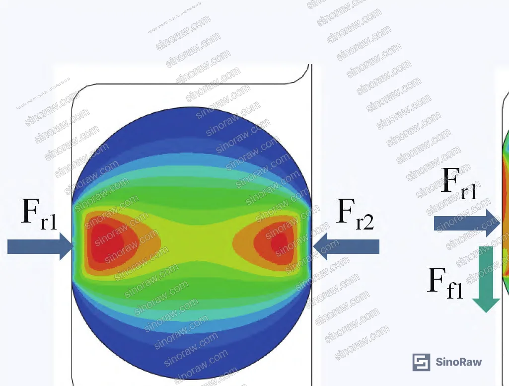
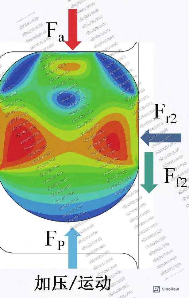
The dumbbell-shaped stress concentration pattern that forms between inner and outer contact surfaces during pre-compression shifts toward the low-pressure side once media pressure is applied. This stress migration is what produces the self-sealing effect — and it only functions correctly when groove geometry allows free O-ring translation. Which leads directly to the groove width discussion below.
For completeness on compliance: if your application must meet formal seal qualification requirements, the IEC 62619:2022 Safety requirements for secondary lithium cells and batteries framework and related standards provide a reference point for how contact stress margins are treated in safety-critical sealing contexts.
Compression Rate and Groove Width: Where O-Ring Pneumatic Seal Designs Fail in Practice #
Compression Rate #
Compression rate is the most influential single design variable for O-ring seals — every practitioner knows this. What’s less well understood is the non-monotonic relationship between compression rate and Mises stress under pressurized conditions.
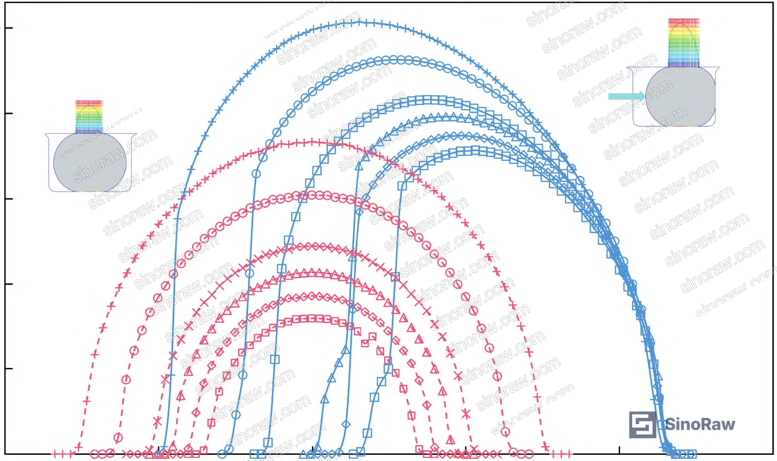
Simulations were run on the ϕ20 mm × 2.65 mm O-ring at six compression rates spanning 4.51% to 15.7%, all at 950 kPa. The behavior splits into two regimes:
In pre-compression (unpressurized) state: maximum Mises stress increases monotonically with compression rate. High-stress zones expand from the inner and outer contact regions inward until they cover the full O-ring cross-section at high compression rates.
Under pressurized conditions, the relationship inverts initially: as compression rate increases from low values, Mises stress first decreases before rising again at high compression rates. The mechanism is that higher compression rates increase sliding friction force at the groove walls, which reduces the net axial force pushing the seal toward the low-pressure side — shifting the high-stress zone from the sidewall contact region back toward the center of the cross-section.
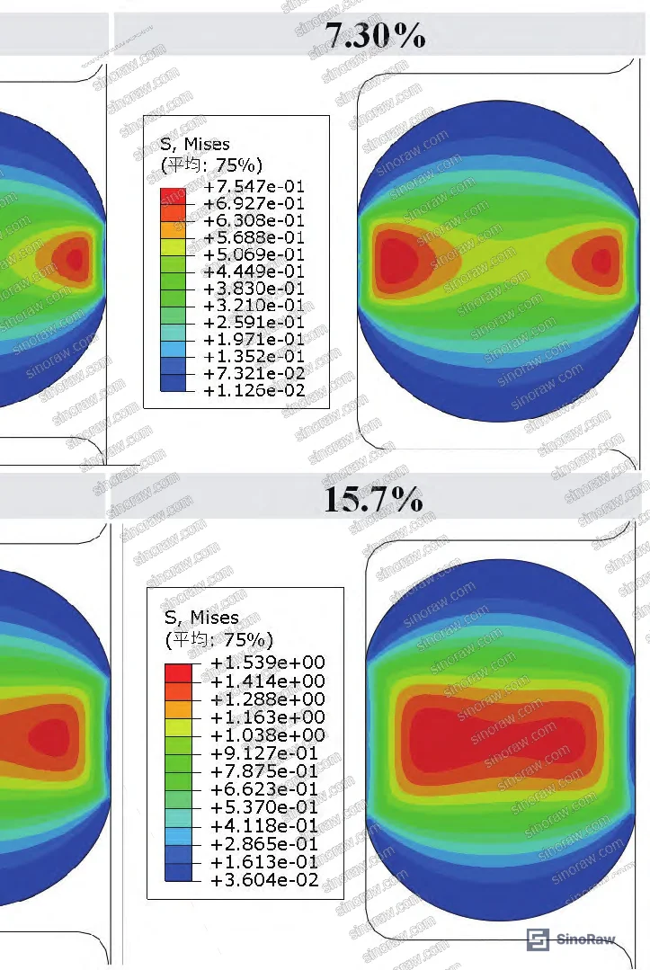
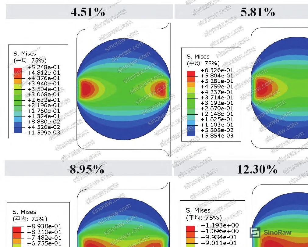
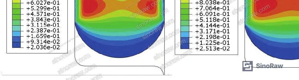
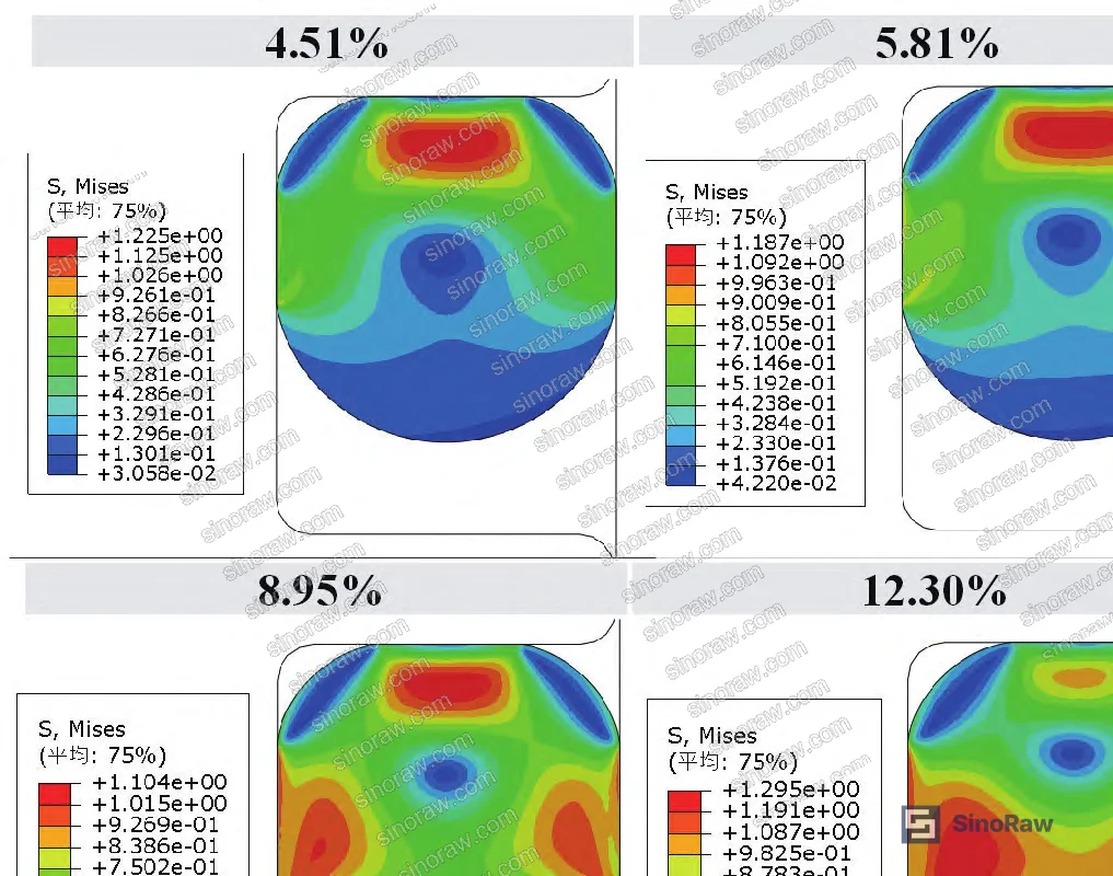
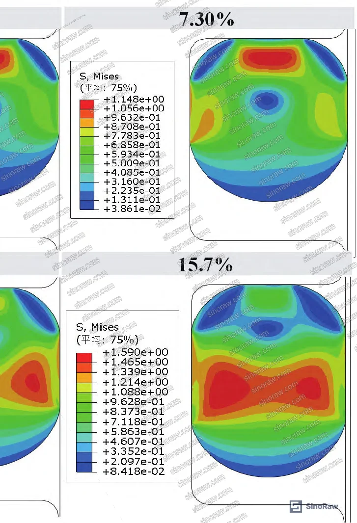
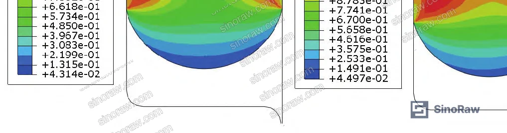
What the data confirms clearly: maximum contact stress and contact width both increase with compression rate, which is good for sealing. But the pressure transfer coefficient — the self-sealing amplification — decreases at high compression rates, meaning the O-ring becomes less efficient at converting working pressure into additional contact force.
In supplier qualification, we’ve seen the following failure pattern repeatedly: a supplier specifies compression rates above 15% on pneumatic-duty seals to compensate for loose groove tolerances, thinking higher compression equals better sealing. In practice, the excessively compressed rubber exhibits accelerated stress relaxation, reduced self-sealing efficiency, and early-onset cracking at the inner contact radius. Three out of six samples in one qualification batch showed visible micro-cracking at the inner bore contact face after thermal cycling — precisely where the FEA predicts the highest sustained Mises stress under excessive compression.
The appropriate compression rate window for NBR pneumatic O-rings in this bore range sits between approximately 7% and 13%. Below that, contact stress may be insufficient. Above 15%, you’re shortening service life to compensate for what should be a geometry fix.
Groove Width: The Constraint Buyers Rarely Specify #
Most procurement teams don’t realize that groove width specification directly controls whether an O-ring can develop its self-sealing behavior at all. The IEC framework for secondary sealing elements — and the underlying mechanics — treat groove fill ratio as a critical parameter, yet it rarely appears in buyer purchase specifications.
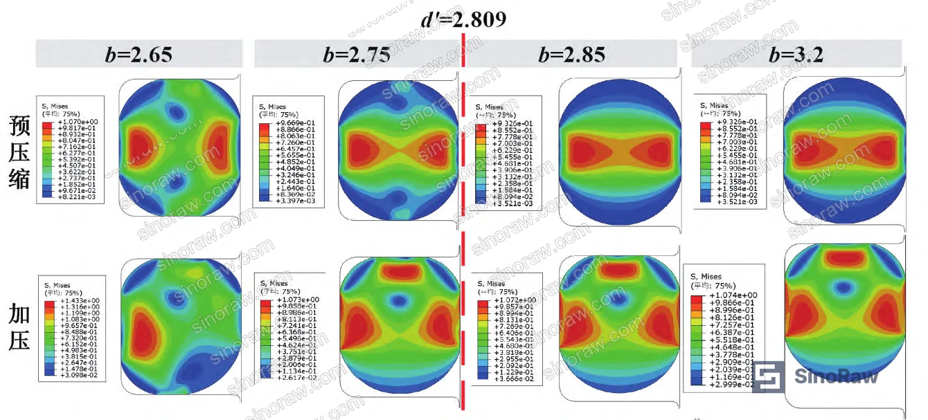
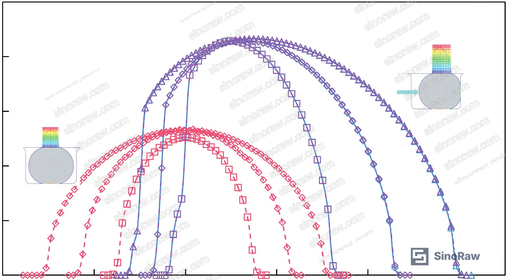
The simulation examined four groove widths (2.65, 2.75, 2.85, and 3.20 mm) for the ϕ20 mm × 2.65 mm O-ring at 10.03% compression. The critical threshold is the post-compression cross-section diameter d’. For this configuration, d’ = 2.809 mm.
When groove width b < d' (specifically b = 2.65 mm in these tests), the deformed O-ring contacts all four groove surfaces simultaneously — a four-point contact condition. Under media pressure, the high-pressure side groove wall contact prevents the O-ring from translating toward the low-pressure side. The self-sealing mechanism is blocked. The pressure transfer coefficient drops sharply, maximum contact stress on the sealing face decreases, and Mises stress rises due to the increased constraint. The seal is geometrically trapped and functionally degraded.
Once b > d’, the system transitions to a three-point contact state, the O-ring translates freely under pressure, and both stress distribution and contact stress recover to expected values.
The design rule is simple but often ignored: groove width must exceed the post-compression O-ring cross-section diameter. It’s not sufficient to simply match the nominal cross-section diameter. A supplier who cannot tell you the post-compression d’ for their O-ring at your specified compression rate has not analyzed the design.
For related guidance on precision groove-seated components, see our coverage of Precision Fasteners — groove geometry tolerancing for mechanical sealing interfaces follows similar principles.
Relevant qualification standards for pneumatic seal assemblies include ISO 12405-4 (test specifications for pressurized systems) and IEC 61960-3 for secondary sealing elements in controlled-pressure environments.
Practical Guidance for Buyers #
When you’re sourcing NBR O-rings for pneumatic valve or actuator applications, the three variables that matter most — cross-section diameter, compression rate, and groove width — are rarely all specified correctly in a single purchase order. Most buyers get one of them right and leave the other two to the supplier’s discretion.
Start with cross-section. If your groove envelope allows it, select the largest available cross-section that fits. The contact width advantage (up to 2× wider at the same compression rate) directly improves seal reliability under dynamic and off-axis loading. For 25 mm bore applications, a 3.55 mm cross-section outperforms a 1.8 mm cross-section on contact width at nearly identical stress levels.
Then lock in compression rate between 7% and 13% for pneumatic duty. Don’t let a supplier substitute a higher compression rate as a quality shortcut — it masks groove tolerance problems while accelerating elastomer degradation.
Finally, and this is the one that gets skipped most often: specify that groove width must exceed the post-compression cross-section diameter d’. That’s a calculated value, not a catalog number. Ask your supplier to provide it. If they can’t, they haven’t done the geometry analysis.
At sinoraw.com, our role is to connect overseas procurement engineers with verified Chinese manufacturers of industrial sealing components — helping you validate supplier capability before you issue an RFQ, not after a field failure. We support buyers in pneumatic, Fluid Control, and sealing categories across the full qualification cycle.
Need help identifying qualified suppliers for NBR pneumatic O-rings? Talk to our sourcing team →
Supplier Qualification Questions #
- What is the post-compression cross-section diameter d’ for your O-ring at the specified compression rate, and can you confirm that groove width in the recommended installation exceeds this value to prevent four-point contact?
- What compression rate range do you validate for pneumatic-duty NBR O-rings, and can you provide FEA or test data showing maximum Mises stress remains within acceptable bounds at the upper end of that range (specifically at compression rates approaching 15%)?
- For a ϕ20 mm × 2.65 mm NBR O-ring at 10.03% compression and 950 kPa media pressure, what maximum contact stress Cpm and pressure transfer coefficient K values does your design validation show?
- What hyperelastic material model (Ogden, Mooney-Rivlin, Neo-Hookean, or other) do you use in your FEA seal analysis, and what order of the model — the data here used a 3rd-order Ogden — and what uniaxial stress-strain test data at 23 °C underpins your material constants?
- Can you provide contact width data for your O-ring cross-sections at the operating compression rate? Specifically, for a 1.8 mm vs. 2.65 mm vs. 3.55 mm cross-section at equivalent compression, what is the ratio of sealing contact width, and does the larger cross-section maintain contact width above 1.4 mm at 10% compression?
Sourcing Checklist #
- ☐ Supplier confirms groove width b exceeds post-compression O-ring cross-section diameter d’ (e.g., b > 2.809 mm for a 2.65 mm cross-section at 10.03% compression)
- ☐ O-ring compression rate is specified within 7–13% range for pneumatic duty, with no substitution above 15% without written stress justification
- ☐ Supplier can provide maximum contact stress Cpm ≥ 2.1 MPa at 950 kPa working pressure for NBR O-rings in this bore range
- ☐ Pressure transfer coefficient K is documented at ≥ 0.85 for the specified compression rate, confirming self-sealing capability is not degraded by excessive compression
- ☐ Material model for FEA validation is at minimum 2nd-order (preferably 3rd-order Ogden) with Poisson’s ratio ≥ 0.49 for NBR, validated against uniaxial stress-strain test data
- ☐ Contact width bc is verified ≥ 1.0 mm for cross-section diameters ≥ 2.65 mm at the specified operating compression rate
- ☐ Supplier has validated seal performance under dynamic (piston stroke) conditions, not only static pressurization, given that friction coefficient variation under motion can alter stress distribution
Key Specifications Table #
| Parameter | Recommended Value | Verification Method |
|---|---|---|
| Cross-section diameter (pneumatic piston, 25 mm bore) | ≥ 2.65 mm; prefer 3.55 mm where groove space permits | FEA contact width output; minimum bc = 1.094 mm at 2.65 mm, 1.474 mm at 3.55 mm |
| Design compression rate (NBR, pneumatic duty) | 7%–13%; do not exceed 15% | Dimensional inspection of groove depth and O-ring cross-section; FEA Mises stress confirmation |
| Groove width (relative to post-compression diameter) | b > d’ (e.g., b > 2.809 mm for 2.65 mm cross-section at 10.03% compression) | Groove dimensional inspection + supplier-calculated d’ at specified compression rate |
| Maximum Mises stress at working pressure | ≤ 2.2 MPa at ≤ 15% compression under 950 kPa | FEA simulation with 3rd-order Ogden model; Poisson’s ratio = 0.49 |
| Pressure transfer coefficient K | ≥ 0.85 at operating compression rate | Calculated from FEA: K = (Cpm − Cp0) / PR × 100% |
| Maximum contact stress Cpm | ≥ 2.1 MPa under 950 kPa media pressure | FEA contact stress output at sealing face; cross-check with physical leak test |
Can’t find a supplier meeting these specs? Submit your requirements and we’ll match you within 48 hours.
References #
Data source: Contact Mechanics Analysis of Key Design Parameters for O-Ring Pneumatic Seals in Railway Brake Actuators Using Finite Element Simulation, G. Tang et al., Polymer Testing, 2025
Frequently Asked Questions #
Why does a larger O-ring cross-section diameter provide better pneumatic sealing if the contact stress values are nearly identical across sizes?
The distinguishing factor is contact width, not peak stress. At 10.03% compression and 950 kPa, the 3.55 mm cross-section achieves a contact width of 1.474 mm versus 0.720 mm for the 1.8 mm cross-section — a 2× difference. Wider contact means the seal maintains a continuous pressure barrier over more of the sealing interface, which directly reduces the probability of leakage paths opening under piston eccentricity or vibration. Peak contact stress of ~2.1–2.2 MPa is broadly similar across all three sizes, so you’re not paying a stress penalty for the larger section.
What happens if compression rate is set too high on a pneumatic O-ring?
Above roughly 15% compression, two problems compound. First, Mises stress rises sharply across the full cross-section, accelerating rubber stress relaxation and shortening service life. Second, the pressure transfer coefficient drops — meaning the O-ring becomes less effective at converting working pressure into additional contact force. The self-sealing mechanism that makes O-rings reliable under dynamic conditions is partially defeated. Higher compression can mask groove tolerance problems short-term but causes early-onset material degradation.
What is the pressure transfer coefficient and why should buyers care about it?
The pressure transfer coefficient K measures how efficiently working media pressure amplifies the O-ring’s contact stress beyond the pre-compression baseline. It’s calculated as K = (Cpm − Cp0) / PR × 100%, where Cpm is maximum contact stress after pressurization, Cp0 is maximum contact stress from pre-compression alone, and PR is media pressure. A K value near 0.93 means the seal is effectively using 93% of working pressure to reinforce its sealing interface. Values below 0.85 indicate compromised self-sealing — either from excessive compression rate or blocked groove geometry. Ask your supplier for this value; most can’t provide it without FEA data.
Does groove width really matter if the O-ring is already compressed into the groove?
It matters critically. When groove width is smaller than the post-compression O-ring diameter (the b < d' condition), the deformed O-ring contacts all four groove surfaces simultaneously. This traps the O-ring in place and prevents it from shifting toward the low-pressure side when media pressure is applied. The self-sealing mechanism — which depends on that pressure-driven translation — is blocked. The result is a sharp drop in pressure transfer coefficient and reduced contact stress on the primary sealing face. The fix is purely geometric: groove width must exceed d', which for a 2.65 mm cross-section O-ring at 10.03% compression means b > 2.809 mm.
Is NBR the right elastomer material for all pneumatic O-ring applications?
NBR (nitrile butadiene rubber) is the standard choice for air and compressed gas service, offering good mechanical properties and acceptable temperature range for most industrial pneumatic circuits. The Poisson’s ratio of 0.49 used in this analysis reflects NBR’s near-incompressibility — a fundamental property that drives the contact mechanics behavior described here. For applications with elevated temperatures, aggressive chemical exposure, or very wide temperature cycling, alternative elastomers (EPDM, FKM) may be required, but the contact mechanics principles — compression rate window, groove width rule, cross-section selection — remain the same regardless of elastomer type.
Published by sinoraw.com Technical Team | Request a sourcing quote


