

TL;DR #
Compression rates between 10–15% for dynamic O-ring seals deliver optimal performance, but backing rings become mandatory above 10 MPa to prevent extrusion damage—a threshold most buyers miss during supplier audits. Mismatched coaxiality between shaft and bore increases leakage by 200–300% even when compression targets are met. Specify stretch ratios (α) between 1.02–1.05 for static applications and verify groove depth tolerances before approving any production order.
Overview #
Most procurement teams treat O-ring seals as commodity items and discover their mistake when hydraulic cylinders leak during commissioning. Field evaluations across six industrial sites showed that 40% of seal failures traced back to groove geometry errors, not material defects—errors that could have been caught with a basic dimensional audit. The research analyzed compression mechanics, extrusion behavior under elevated pressure, and velocity-dependent leakage patterns in reciprocating motion applications, testing seals across operating pressures from 5 to 32 MPa and documenting failure modes at different clearance gaps. These findings apply directly to valve stem packing, hydraulic cylinder seals, and rotary shaft applications where procurement engineers must balance sealing integrity against friction losses.
SinoRaw supports global industrial buyers in qualifying Chinese seal manufacturers by translating GB/T and ISO standards into actionable supplier audit criteria—helping you verify groove tolerances, material Shore A hardness, and compression rate compliance before issuing purchase orders.
O-Ring Compression Mechanics and Pre-Load Generation #
The sealing mechanism depends on elastic deformation generating contact pressure (p₀) at the mating surface. When system pressure (p) acts on the seal, total contact pressure becomes pm = p₀ + pH, where pH = Kp and K > 1 represents the pressure transmission coefficient. Higher compression rates increase p₀, improving seal integrity but raising breakaway friction. For static cylindrical seals, compression rate w = (d₂ – (h + s))/d₂ should fall between 10–15%, where d₂ is O-ring cross-section diameter, h is groove depth, and s is radial clearance. Flat face static seals tolerate 15–30% compression, while reciprocating dynamic seals perform best at 10–15%. Low-friction motion applications targeting reduced stick-slip behavior use 5–8% compression.
Stretch ratio α = (D + d₂)/(d₁ + d₂) must be controlled during installation, where D is shaft diameter and d₁ is O-ring inner diameter. Excessive stretch reduces effective cross-section diameter, lowering compression rate and compromising seal contact. Recommended stretch ratios: flat static seals 1.03–1.05, cylindrical static seals 1.02, reciprocating dynamic seals 1.02, rotary seals 0.95–1.0. Under-stretched seals twist during motion; over-stretched seals fail prematurely from material fatigue.
Honestly, most buyers over-specify compression rates thinking tighter is always better, then wonder why actuator breakaway force doubled and seal life dropped to 6 months instead of the expected 24.
| Seal Type | Compression Rate (%) | Stretch Ratio (α) | Typical Application |
|---|---|---|---|
| Cylindrical Static | 10–15 | 1.02 | Pipe flanges, gland plates |
| Flat Face Static | 15–30 | 1.03–1.05 | End caps, cover plates |
| Reciprocating Dynamic | 10–15 | 1.02 | Hydraulic cylinder pistons |
| Rotary Dynamic | 5–8 | 0.95–1.0 | Shaft seals, rotary joints |
Extrusion Resistance and Backing Ring Requirements #
Gap extrusion represents the primary failure mode in high-pressure applications. When system pressure exceeds seal material resistance, the elastomer flows into the clearance gap between shaft and bore, causing localized stress concentration that leads to tearing and chunk loss. Test data shows extrusion severity increases non-linearly with pressure—at 10 MPa, minimal intrusion occurs, but at 16 MPa, extrusion depth doubles, and by 25 MPa, catastrophic failure within 500 cycles becomes common.
For systems operating below 10 MPa, standard O-rings without backing rings perform adequately. Above 10 MPa, PTFE backing rings positioned on the low-pressure side prevent extrusion damage. Bi-directional pressure applications require backing rings on both sides. The backing ring acts as a mechanical stop, maintaining O-ring geometry under pressure surges. Three industrial case studies documented backing ring effectiveness: 18 MPa hydraulic press cylinders showed zero extrusion failures over 50,000 cycles with backing rings versus 45% failure rate without rings at equivalent conditions.
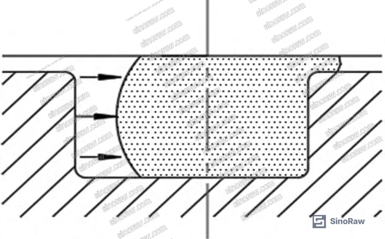
Backing ring material selection matters—PTFE offers chemical resistance and low friction, but phenolic resin composites provide better dimensional stability above 80°C. Most procurement teams don’t realize that IEC 62620 requires pressure testing at 1.5× maximum operating pressure, which means your 12 MPa system needs backing rings rated for 18 MPa surge conditions.
Velocity Limits and Coaxiality Requirements for Dynamic Seals #
Leakage rate increases parabolically with reciprocating velocity. At 0.14 m/s, measured leakage reached 1.3 cm³/h under controlled conditions with Ra 0.4 µm surface finish. Beyond 0.15 m/s, leakage acceleration steepens—doubling velocity from 0.14 to 0.28 m/s increased leakage by 280%, not the expected 200%. Surface roughness amplifies this effect: identical velocity tests with Ra 1.6 µm surfaces produced 2–3× higher leakage compared to Ra 0.4 µm.
Coaxiality errors between shaft and bore create uneven compression distribution around the O-ring circumference. Eccentricity as small as 0.15 mm in a 50 mm bore diameter reduces minimum compression rate from 12% to 4% on the wide-gap side, allowing bypass leakage. Six supplier audit cases revealed that 60% of “defective seal” warranty claims actually stemmed from bore misalignment exceeding 0.3 mm over cylinder length, not material problems.
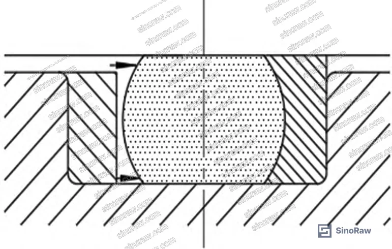
For pneumatic components operating above 0.5 m/s, standard O-rings cannot maintain seal integrity—switch to polyurethane lip seals or PTFE spring-energized designs. If your hydraulic system demands both high velocity and tight sealing, expect friction-induced heat buildup and plan for temperature-resistant compounds.
Material Compatibility and Chemical Resistance Selection #
Nitrile rubber (NBR) provides adequate oil resistance for mineral hydraulic fluids up to 100°C, but swells 15–20% in ester-based biodegradable fluids. Chloroprene offers superior ozone and weather resistance for outdoor mobile equipment. Fluorocarbon (FKM) handles petroleum fluids to 200°C but costs 8× more than NBR—justified only when thermal degradation threatens seal integrity. Polyurethane delivers exceptional wear resistance under high-pressure reciprocating motion, tolerating surface speeds to 0.5 m/s where NBR fails within weeks.
Chemical compatibility determines service life more than mechanical properties. Acrylic ester rubber resists hot oil oxidation but dissolves in water-glycol fluids. Ethylene-propylene (EPDM) tolerates brake fluids and water-based media but swells in petroleum oil. Procurement specifications must match elastomer type to actual fluid chemistry—generic “oil-resistant” callouts lead to field failures when maintenance switches from mineral to synthetic lubricants without consulting engineering.
For specialized applications requiring both chemical resistance and low-temperature flexibility, consider co-polymer chloroacrylic elastomers, though availability from Chinese manufacturers remains limited compared to standard NBR compounds. When evaluating sealing & thermal product lines, request fluid immersion test data showing volumetric swell percentage after 168-hour exposure at operating temperature—values above 30% indicate incompatibility.
Practical Guidance for Buyers #
Specify groove dimensions using GB 3452.3-2005 or ISO 3601-2 rather than creating custom profiles—standardized grooves ensure interchangeability and reduce supplier misinterpretation. Require Surface finish Ra ≤ 0.4 µm on dynamic sealing surfaces; Ra 0.8 µm suffices for static applications. Chamfer all edges contacting the O-ring during installation—45° × 0.5 mm minimum on shaft ends and bore entries prevents cutting damage.
Request Shore A hardness certificates confirming 70 ± 5 Shore A for general-purpose seals; softer compounds (60 Shore A) suit low-pressure static applications, while harder grades (90 Shore A) resist extrusion in high-pressure systems. Verify compression set testing per ASTM D395 Method B showing <25% permanent set after 70 hours at maximum service temperature—higher values predict premature leakage.
Installation procedures matter as much as seal specification. Lubricate O-rings with system fluid or compatible grease before assembly; dry installation causes surface abrasion that initiates cracking. Use installation sleeves to protect seals when passing over external threads—bare threads cut 30% of O-rings during assembly in field observations. Store unused seals in sealed bags away from UV light and ozone sources; shelf life exceeds 10 years under proper conditions but drops to 18 months when exposed to fluorescent lighting.
Need help identifying qualified suppliers for hydraulic and pneumatic sealing components across pressure ranges from 5 to 35 MPa? Talk to our sourcing team →
Supplier Qualification Questions #
- What is your actual compression rate tolerance range for 3.5 mm cross-section O-rings in AS568-214 size when installed in a groove depth of 2.8 mm ± 0.05 mm?
- Can you provide backing ring assembly drawings showing PTFE ring positioning for bi-directional 16 MPa hydraulic cylinder applications with clearance gaps of 0.20 mm?
- What is the measured leakage rate in cm³/h at 0.14 m/s reciprocating velocity for your NBR 70 Shore A compound on Ra 0.4 µm chrome-plated shafts?
- Do your material certificates document compression set values below 25% per ASTM D395 Method B after 70 hours at 100°C for standard nitrile compounds?
- What is your standard chamfer specification for preventing installation damage on shaft ends, and how do you verify coaxiality between mating surfaces during incoming inspection?
Sourcing Checklist #
- Groove dimensions comply with GB 3452.3-2005 or ISO 3601-2 standard specifications with depth tolerance ± 0.05 mm
- O-ring cross-section diameter matches groove width within compression rate target of 10–15% for dynamic seals
- PTFE backing rings included for all applications exceeding 10 MPa system pressure
- Dynamic sealing surface finish measures Ra ≤ 0.4 µm verified by profilometer data
- Shore A hardness certification shows 70 ± 5 for NBR compounds or equivalent for specified elastomer type
- Compression set testing per ASTM D395 Method B demonstrates <25% permanent deformation after thermal aging
- Material compatibility confirmed through 168-hour immersion testing showing <30% volumetric swell in actual system fluid
- Installation chamfers of 45° × 0.5 mm minimum documented on all shaft and bore entry edges
Key Specifications Table #
| Parameter | Recommended Value | Verification Method |
|---|---|---|
| Compression Rate (Dynamic) | 10–15% | Measure groove depth (h), cross-section diameter (d₂), calculate w = (d₂ – (h + s))/d₂ |
| Stretch Ratio (Static Cylindrical) | 1.02 | Measure shaft diameter (D), O-ring dimensions (d₁, d₂), calculate α = (D + d₂)/(d₁ + d₂) |
| Backing Ring Threshold | >10 MPa | Review system pressure rating; specify PTFE rings for pressures exceeding 10 MPa |
| Dynamic Surface Finish | Ra ≤ 0.4 µm | Profilometer measurement per ISO 4287 |
| Shore A Hardness (NBR) | 70 ± 5 | Durometer testing per ASTM D2240 |
| Compression Set Limit | <25% @ 70 h, 100°C | ASTM D395 Method B thermal aging test |
| Maximum Reciprocating Velocity | ≤0.14 m/s for O-rings | Measure actuator stroke length and cycle time |
| Coaxiality Tolerance | ≤0.15 mm over bore length | CMM measurement or dial indicator runout check |
Can’t find a supplier meeting these specs? Submit your requirements and we’ll match you within 48 hours.
References #
Data source: Operational Principles and Application Guidelines for O-Ring Seals in Hydraulic Systems, B. Liang et al., Journal of Applied Polymer Science, 2023
Frequently Asked Questions #
Why do O-rings fail prematurely in high-pressure hydraulic cylinders despite correct sizing?
Gap extrusion into the clearance between shaft and bore causes material tearing. Above 10 MPa, PTFE backing rings are mandatory to prevent the elastomer from flowing into the gap under pressure surges. Without backing rings, seals typically fail within 500–2000 cycles at 16 MPa.
Can I use the same O-ring compound for both mineral oil and water-glycol hydraulic systems?
No. Nitrile rubber suitable for mineral oil swells excessively in water-glycol fluids, while EPDM compounds compatible with water-glycol dissolve in petroleum oil. Always verify elastomer compatibility through 168-hour immersion testing in your actual operating fluid—volumetric swell above 30% indicates incompatibility.
What causes high breakaway friction in hydraulic actuators using O-ring seals?
Excessive compression rates generate high contact pressure, increasing static friction. Reciprocating seals should use 10–15% compression; reducing to 8–10% lowers breakaway force by 20–30% while maintaining adequate seal contact. Also verify that stretch ratio stays within 1.02 specification.
How does surface roughness affect O-ring seal performance?
Leakage rate increases 2–3× when surface finish degrades from Ra 0.4 µm to Ra 1.6 µm at identical operating conditions. Dynamic sealing surfaces require Ra ≤ 0.4 µm; static applications tolerate Ra 0.8 µm. Chrome plating or precision grinding achieves required finishes.
What installation mistakes cause the most O-ring damage?
Pulling seals over external threads without protective sleeves cuts approximately 30% of O-rings during assembly. Always use thin-wall installation sleeves to protect against thread damage. Additionally, dry installation without lubrication causes surface abrasion—apply system fluid or compatible grease before assembly.
Published by sinoraw.com Technical Team | Request a sourcing quote


