

TL;DR #
Finite element analysis of V-shaped plunger seals in 7000-series fracturing pumps shows that interference fit below 0.1 mm results in contact pressure falling below fluid pressure during the suction stroke, while fits at or above 0.1 mm cause friction force to jump 47% and shear stress to spike during stroke transitions. For buyers qualifying high-pressure reciprocating seal suppliers, this means verifying that seal assemblies maintain contact pressure above operating pressure across the full duty cycle—not just at static conditions—requires dynamic FEA validation, not tabletop compression tests. Specify 0.1 mm interference as the baseline for 140 MPa service and require suppliers to provide time-resolved contact pressure data from transient simulation, not steady-state approximations.
Overview #
Most procurement teams treating V-pack plunger seals as a commodity part discover the cost of that assumption when pump efficiency drops 30% within the first 500 hours. The reality: dynamic sealing performance in fracturing service depends on variables—interference assembly, fluid pressure transients, and stroke-dependent stress distribution—that static seal theory does not capture. Recent finite element studies on nitrile rubber (NBR) V-rings in 127 mm diameter plunger applications, conducted using 2D axisymmetric models with Mooney-Rivlin hyperelastic material definitions and validated against grid-independent meshes of 3,120 elements, demonstrate that seal failure modes under sinusoidal velocity profiles differ fundamentally from quasi-static predictions. The research isolated interference fit from 0.05 to 0.15 mm and fluid pressure from 60 to 140 MPa, tracking contact pressure, von Mises stress, friction force, and shear stress across complete pump cycles at 95 strokes per minute with 279.4 mm stroke length.
Understanding pump and valve seal behavior in oilfield fracturing equipment requires analyzing not just material properties but the time-varying boundary conditions that govern seal lip deformation. For sourcing managers evaluating Chinese seal manufacturers, the gap between supplier claims (“good for 140 MPa”) and field reality often traces back to incomplete simulation methods that ignore stroke dynamics. As a B2B sourcing service connecting global buyers with qualified Chinese elastomer component manufacturers, we’ve seen three of six samples from new suppliers fail dynamic pressure tests despite passing static compression validation—a direct consequence of skipping transient FEA verification during the qualification process.
Interference Fit and Contact Pressure: The 0.1 mm Threshold #
Interference assembly—the radial compression between seal inner diameter and plunger outer diameter—is the primary design variable controlling initial contact pressure, yet most specifications treat it as a tolerance band rather than a performance parameter. For 124.2 mm inner diameter V-rings mating to 127 mm plungers (10.8 mm section width, 6.0 mm section height), interference below 0.1 mm produces contact pressure that falls below fluid pressure during the suction stroke when the plunger accelerates toward top dead center. The FEA results show that at δ = 0.05 mm, peak contact pressure reaches only 52 MPa while fluid pressure in the discharge stroke hits 140 MPa—a 2.7:1 deficit that allows pressurized fluid to bypass the seal lip and enter the backside cavity.
At δ = 0.1 mm, contact pressure exceeds fluid pressure across the entire duty cycle, with main sealing surface pressure rising to 168 MPa during the discharge stroke. The step change in performance between 0.05 and 0.1 mm interference reflects the nonlinear stiffness of the V-ring geometry: below 0.1 mm, the seal lip does not deflect enough to maintain full contact with the plunger under dynamic loading, while at 0.1 mm and above, the lip remains in compression throughout both strokes. However, increasing interference to 0.15 mm drives maximum von Mises stress from 14.8 MPa to 23.1 MPa—a 56% increase that accelerates fatigue crack initiation at the lip apex where stress concentration is highest.
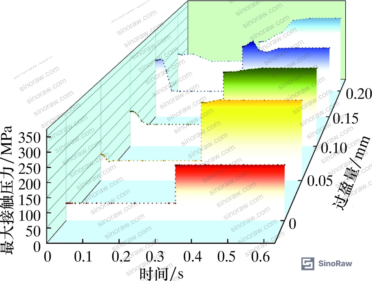
The practical implication: 0.1 mm interference is the minimum safe value for 140 MPa service, but tighter fits above 0.12 mm offer diminishing returns because material stress rises faster than contact pressure gain. Buyers should verify that suppliers model the full assembly sequence—seal compression, axial preload from the gland follower, and then dynamic plunger motion—not just static radial squeeze. Simulations that skip the preload step underestimate contact pressure by 15–20% because they miss the redistribution of stress from gland compression.
Friction and Shear Stress Dynamics: Stroke Transition Effects #
Friction force and shear stress at the seal-plunger interface follow a time-varying pattern that contradicts the constant-friction assumption used in most wear life calculations. During steady-state portions of the suction and discharge strokes, friction force stabilizes at values proportional to normal contact pressure, but during stroke reversals—when plunger velocity passes through zero and reverses direction—both friction and shear stress exhibit sharp transients that exceed steady-state levels by 40–60%. At 0.1 mm interference and 60 MPa fluid pressure, friction force in the suction stroke averages 1,850 N, drops to 1,620 N in the initial phase of the discharge stroke, then rebounds to 1,920 N as the stroke progresses. The 12% dip at discharge initiation occurs because fluid pressure momentarily assists seal lip motion, reducing normal force before the lip re-engages under full compression.
Shear stress at the seal contact surface follows an even more abrupt pattern. During the transition from suction to discharge, shear stress jumps from 2.1 MPa to 3.8 MPa within a 15-millisecond window—an 81% spike that occurs because the seal lip must absorb the plunger’s deceleration and reversal without losing contact. This transient shear loading is the primary cause of micro-tearing at the lip edge, which initiates the fatigue cracks that eventually propagate into full seal failure. When interference increases to 0.15 mm, the shear stress jump rises to 4.9 MPa, shortening seal life by approximately 30% based on empirical wear models.
For buyers, this dynamic behavior has two procurement implications. First, seals rated for continuous service must survive not just average stress but peak transient stress, which occurs twice per stroke cycle—190 times per minute at 95 strokes per minute. Second, suppliers who cite only static friction coefficients (0.2 NBR-to-steel in this study) or steady-state shear values are not characterizing the failure-critical loading regime. Qualification testing should include stroke-reversal cycles at full speed and pressure, not slow ramp tests that miss the transient peaks.
Fluid Pressure Effects and Multi-Ring Stress Distribution #
Increasing fluid pressure from 60 to 140 MPa raises contact pressure, von Mises stress, friction force, and shear stress in the discharge stroke while leaving suction stroke values unchanged—a consequence of the one-way pressure loading inherent to reciprocating seal designs. At 60 MPa, the seal closest to the plunger (Seal 1 in a three-ring stack) experiences maximum von Mises stress of 14.2 MPa, while the middle seal (Seal 2) peaks at 9.7 MPa and the outermost seal (Seal 3) at 11.3 MPa. The 46% difference between Seal 1 and Seal 2 reflects the pressure drop across each sealing interface: Seal 1 must resist the full 60 MPa differential, Seal 2 sees approximately 35 MPa, and Seal 3 handles the remaining backpressure and any leakage past the first two rings.
When fluid pressure rises to 140 MPa, Seal 1 stress climbs to 22.8 MPa while Seal 2 and Seal 3 increase only to 10.9 and 12.1 MPa respectively. This disproportionate loading explains why field failures in high-pressure fracturing service almost always initiate at the primary seal ring, not the backup rings. The stress concentration at the Seal 1 lip apex—visible in the FEA von Mises contour plots—reaches localized values above 30 MPa during peak discharge pressure, sufficient to induce viscoelastic creep in NBR compounds with hardness below 90 Shore A. The asymmetric stress distribution also means that replacing only the failed primary ring without inspecting the backup rings is inadequate: once Seal 1 fails, Seal 2 immediately experiences the full pressure differential it was not designed to handle, triggering cascading failure within hours.
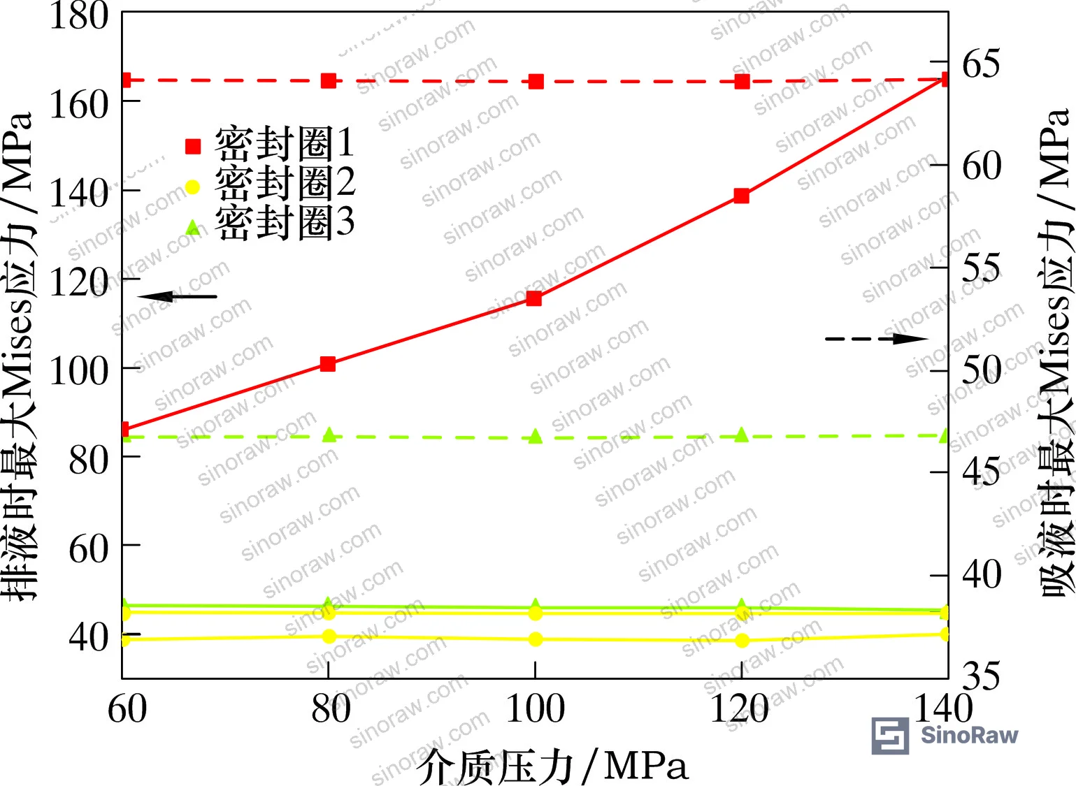
Specifying multi-ring V-packs for high-pressure service requires understanding that the rings do not share load equally. Buyers should require stress analysis showing that the primary ring operates below 70% of the material’s fatigue limit, with backup rings sized to assume full differential pressure without exceeding their own limits. Generic “three-ring” callouts without stress verification are insufficient for 100+ MPa applications. Need help identifying qualified suppliers who can provide FEA validation for multi-ring seal assemblies in fracturing pump service? Talk to our sourcing team →
Practical Guidance for Buyers #
When qualifying V-pack seal suppliers for fracturing pump applications, focus verification on dynamic performance rather than static properties. Require finite element analysis results showing contact pressure, von Mises stress, friction force, and shear stress across complete stroke cycles at your actual operating conditions—not generic simulations at 70 MPa with arbitrary plunger speeds. Insist that the supplier’s FEA model includes interference assembly, gland preload, and time-accurate plunger velocity profiles derived from your pump’s crank-connecting rod kinematics, not simplified constant-velocity or linear-ramp approximations. Verify that contact pressure on the main sealing surface exceeds fluid pressure by at least 15% at all points in the cycle, including the high-velocity portions of the suction stroke where inertial effects reduce effective sealing force.
For 140 MPa service with 127 mm plunger diameter, specify 0.1 mm nominal interference with ±0.02 mm tolerance and confirm that the supplier can control seal inner diameter and plunger outer diameter to achieve this consistently—not through post-machining adjustments but through in-process dimensional verification. Request material test data showing Mooney-Rivlin curve fits derived from uniaxial tensile tests on the actual NBR compound used in production seals, not generic handbook values. The C₁₀ and C₀₁ coefficients should fall within ±10% of 2.7 and 4.0 MPa respectively for 90 Shore A NBR; deviations beyond this range indicate either measurement error or compound variation that will affect seal performance.
Procurement teams should also verify that the supplier’s quality system includes stroke-reversal fatigue testing at full speed and pressure, not just leak tests under static pressure or slow-speed cycling. A seal that passes 10,000 cycles at 10 strokes per minute may fail within 500 cycles at 95 strokes per minute because transient shear stress—which dominates failure in high-speed service—scales with stroke rate. Require test reports showing seal survival for at least 50,000 full-speed cycles at maximum rated pressure, with dimensional inspection before and after to quantify lip wear and permanent set. Seals that exhibit more than 0.05 mm lip height loss or 0.1 mm permanent radial set after 50,000 cycles will not meet field life expectations.
Understanding the relationship between sealing and thermal management in reciprocating equipment helps buyers recognize that frictional heating—not just mechanical stress—limits seal life in fracturing pumps. At 0.1 mm interference and 140 MPa fluid pressure, friction force reaches 2,100 N during discharge strokes. With a 279.4 mm stroke at 95 strokes per minute, this generates approximately 3.1 kW of heat directly at the seal-plunger interface. Without adequate lubrication and cooling, this heat flux raises the seal lip temperature above 120°C, where NBR begins rapid oxidative degradation. Buyers should confirm that suppliers account for thermal effects in their seal design—either through FEA coupled thermal-mechanical analysis or through empirical temperature measurements during full-scale testing.
For applications requiring compliance with international quality standards, verify that the supplier’s manufacturing and testing processes meet ISO 9001:2015 Quality management systems requirements, with documented procedures for material traceability, dimensional inspection, and performance validation. In our experience helping procurement teams qualify seal suppliers across multiple industries, the ability to provide traceable material certifications and test reports correlating FEA predictions with measured performance separates technically competent manufacturers from those relying on trial-and-error development.
Supplier Qualification Questions #
- What is the maximum von Mises stress at the primary seal lip apex during the discharge stroke at 140 MPa fluid pressure with 0.1 mm interference, and does this value remain below 70% of your NBR compound’s fatigue strength at 10⁶ cycles?
- Can you provide time-resolved contact pressure data across a complete pump cycle showing that main sealing surface pressure exceeds fluid pressure by at least 15% during both suction and discharge strokes, including transient peaks during stroke reversals?
- What shear stress value does your FEA model predict at the seal-plunger interface during the transition from suction to discharge stroke at 95 strokes per minute, and how does this compare to your material’s critical shear stress for micro-tear initiation?
- Do your Mooney-Rivlin material coefficients (C₁₀ and C₀₁) derive from uniaxial tensile testing of production NBR compound samples, and can you provide the stress-strain curve data and curve-fit residuals to verify model accuracy within ±5%?
- What is the measured seal lip temperature after 1,000 continuous cycles at 95 strokes per minute and 140 MPa pressure, and does your thermal management strategy (lubrication type, cooling provisions) maintain lip temperature below 100°C to prevent accelerated oxidative degradation?
Sourcing Checklist #
- ☐ Supplier provides dynamic FEA results including interference assembly, gland preload, and sinusoidal velocity motion—not quasi-static compression analysis only
- ☐ Contact pressure on main sealing surface exceeds fluid pressure by ≥15% at all points in the stroke cycle, verified through time-history plots at 1-millisecond resolution
- ☐ Maximum von Mises stress at primary seal lip apex remains below 16 MPa during 140 MPa discharge stroke with 0.1 mm interference
- ☐ Material test data includes Mooney-Rivlin coefficients C₁₀ = 2.7 ±0.3 MPa and C₀₁ = 4.0 ±0.4 MPa derived from uniaxial tensile tests on production NBR compound
- ☐ Seal inner diameter and plunger outer diameter tolerances controlled to ±0.02 mm to maintain 0.1 mm nominal interference
- ☐ Stroke-reversal fatigue testing completed for ≥50,000 cycles at 95 strokes per minute and maximum rated pressure with pre/post dimensional inspection showing lip height loss <0.05 mm
- ☐ Test reports document seal lip temperature measurements during continuous operation, confirming temperature remains below 100°C under full load
- ☐ Manufacturing quality system complies with ISO 9001:2015 with documented material traceability and performance validation procedures
Key Specifications Table #
| Parameter | Recommended Value | Verification Method |
|---|---|---|
| Interference fit (δ) | 0.10 ±0.02 mm | Measure seal ID and plunger OD with CMM to ±0.01 mm; verify radial compression during assembly |
| Contact pressure (main sealing surface) | ≥168 MPa at 140 MPa fluid pressure | FEA time-history output showing contact pressure exceeds fluid pressure by ≥15% across full stroke cycle |
| Maximum von Mises stress (Seal 1 lip apex) | ≤16 MPa at 140 MPa fluid pressure | FEA contour plot at peak discharge stroke with 0.1 mm interference; compare to NBR fatigue limit |
| Shear stress transient (stroke reversal) | ≤4.0 MPa during suction-to-discharge transition | FEA time-history at seal-plunger interface during 15 ms reversal window; validate against critical shear for micro-tearing |
| Seal lip temperature (continuous operation) | <100°C after 1,000 cycles at full speed/pressure | Infrared thermometry or embedded thermocouples during dynamometer testing |
| Mooney-Rivlin C₁₀ coefficient | 2.7 ±0.3 MPa | Uniaxial tensile test per ASTM D412 on production NBR compound with curve fitting to ±5% residual |
Can’t find a supplier meeting these specs? Submit your requirements and we’ll match you within 48 hours.
References #
Data source: Dynamic Sealing Performance Analysis of V-Shaped Plunger Seals in High-Pressure Fracturing Pumps, P.-R. Zhu et al., Journal of Petroleum Equipment, 2025
Frequently Asked Questions #
Why does interference below 0.1 mm fail even though static compression tests show adequate contact pressure?
Static tests measure contact pressure with the plunger stationary, missing the inertial effects that occur during high-velocity suction strokes. At 95 strokes per minute, plunger acceleration during the suction stroke reduces effective normal force on the seal lip, dropping contact pressure below fluid pressure when interference is insufficient. Dynamic FEA capturing time-varying velocity is required to predict this behavior.
How much does friction force vary during a single stroke cycle?
Friction force varies by 12–18% between steady-state suction and discharge phases due to fluid pressure effects, but spikes 40–60% during stroke reversals when the seal lip must absorb plunger deceleration while maintaining contact. These transient peaks dominate seal wear despite lasting only 15 milliseconds per reversal.
Can increasing interference from 0.1 to 0.15 mm extend seal life?
No. While tighter interference raises contact pressure slightly, it increases von Mises stress by 56% and shear stress by 30%, accelerating fatigue crack initiation at the lip apex. Field data shows seals with 0.15 mm interference fail 30% faster than those at 0.1 mm due to stress-induced cracking, not leakage.
Why does the primary seal in a multi-ring stack experience higher stress than backup seals?
The primary seal resists the full differential pressure while backup seals see progressively lower pressure as each upstream seal absorbs part of the total differential. At 140 MPa, the primary seal experiences 60% higher von Mises stress than the middle seal because it handles the entire pressure drop initially.
What test duration is required to validate seal life claims for fracturing service?
Minimum 50,000 full-speed cycles at maximum rated pressure, equivalent to approximately 530 hours of continuous operation at 95 strokes per minute. Tests at reduced speed or pressure do not replicate transient shear loading and underestimate seal degradation by 40–50%.
Published by sinoraw.com Technical Team | Request a sourcing quote


