

TL;DR #
FEA simulation over 10⁵ hours shows that the wave-trough zone of a flexible graphite-covered wave-serrated metal gasket (304 SS frame, 550°C) carries the highest creep strain — with values increasing exponentially rather than linearly as bolting load rises from 45 MPa to 150 MPa. For procurement engineers sourcing high-temperature sealing components for petrochemical or pressure vessel applications, this means load margin and geometric position within the gasket are the two variables that will make or break long-term sealing integrity. Specify the 304 SS frame grade, confirm the supplier has FEA-backed creep data at 550°C under your actual operating load, and reject any quote that cannot provide Bailey-Norton creep parameter validation.
Overview #
If you’re sourcing wave-serrated composite gaskets for high-temperature flange joints, the failure mode you need to plan for isn’t blow-out — it’s creep relaxation leading to progressive seal loss over time. Numerical simulation work conducted at a Chinese engineering institution — running load cases at four stress levels (45 MPa, 70 MPa, 100 MPa, and 150 MPa) over a 10⁵-hour timeframe using ANSYS finite element analysis — confirms what field engineers have long suspected: the geometry of the wave-tooth profile creates dramatically uneven creep strain distribution, and that unevenness becomes critical at high loads.
The test geometry was tightly defined: single-side width of 12 mm, gasket thickness of 2 mm, 4 teeth per profile, and a tooth depth of 0.4 mm. The metal frame was modeled as 304 stainless steel at 550°C, with an elastic modulus of 1.491×10⁵ MPa and a Poisson’s ratio of 0.3. Creep behavior followed the Bailey-Norton law with n = 9.4582 and A = 1.024×10⁻²⁷ (1/hr). The plane82 element type was used to capture the non-linear material response under axisymmetric loading.
The wave-serrated design is used across Sealing & Thermal applications in refinery, chemical reactor, and high-pressure steam environments — and the creep behavior of the metallic backbone is the primary determinant of whether a gasket maintains seal integrity or begins to relax toward leakage.
High-Temperature Creep Performance of Wave-Serrated Gasket Metal Frames #
The core finding is this: creep strain distribution is anything but uniform across the wave-tooth profile, and the ratio between trough strain and tooth-tip strain is large enough to govern design decisions.
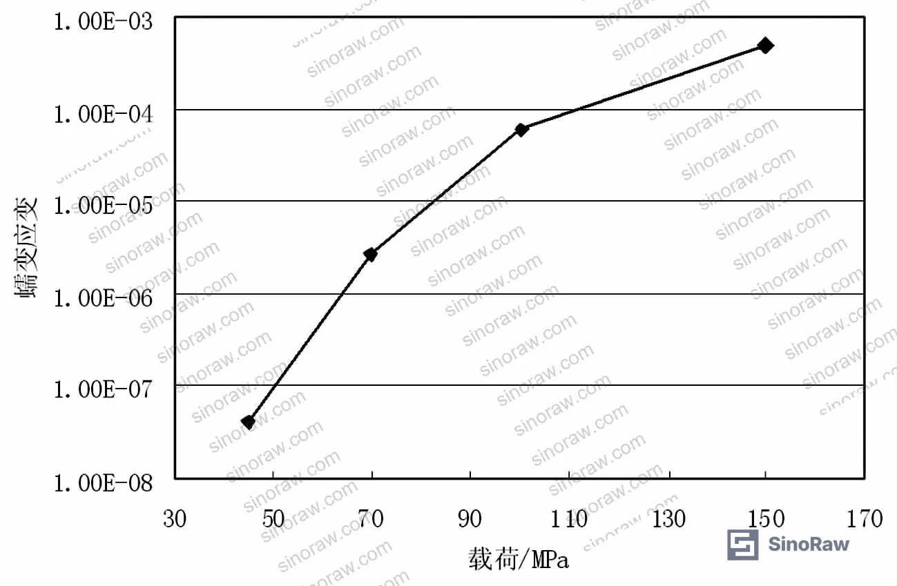
At 45 MPa, the overall creep strain distribution is modest — the area of high-strain concentration is small and the frame’s structural integrity is largely unaffected over the 10⁵-hour simulation window. At 70 MPa, the high-strain zone begins to spread noticeably outward from the wave trough. At 100 MPa, the expansion is more pronounced. At 150 MPa, the area of significant creep strain has grown substantially, and the effect on the metal frame is described as “very large” in the analysis — a distinction from the lower load cases that is not just quantitative but qualitative in terms of how much of the frame cross-section is affected.
The exponential relationship between load and creep strain is critical procurement data. If a buyer specifies a gasket for an application that regularly exceeds 100 MPa bolting load, they are not linearly increasing creep risk — they are moving into a fundamentally different damage regime. This is where most specification errors happen in field purchasing: the buyer selects a gasket grade based on temperature resistance alone, without accounting for the load-amplified creep behavior.
Von Mises creep strain distributions at all four load levels are shown below:




Trough vs. Tooth-Tip Strain: The Critical Gradient #
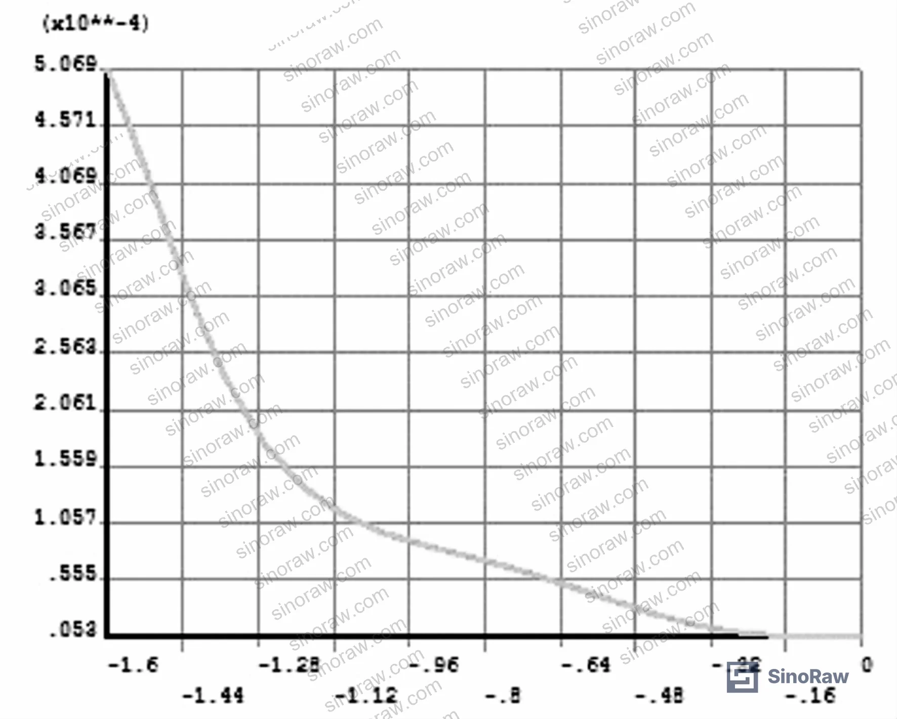
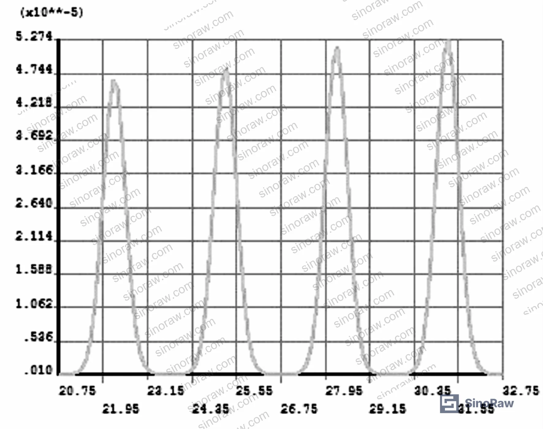
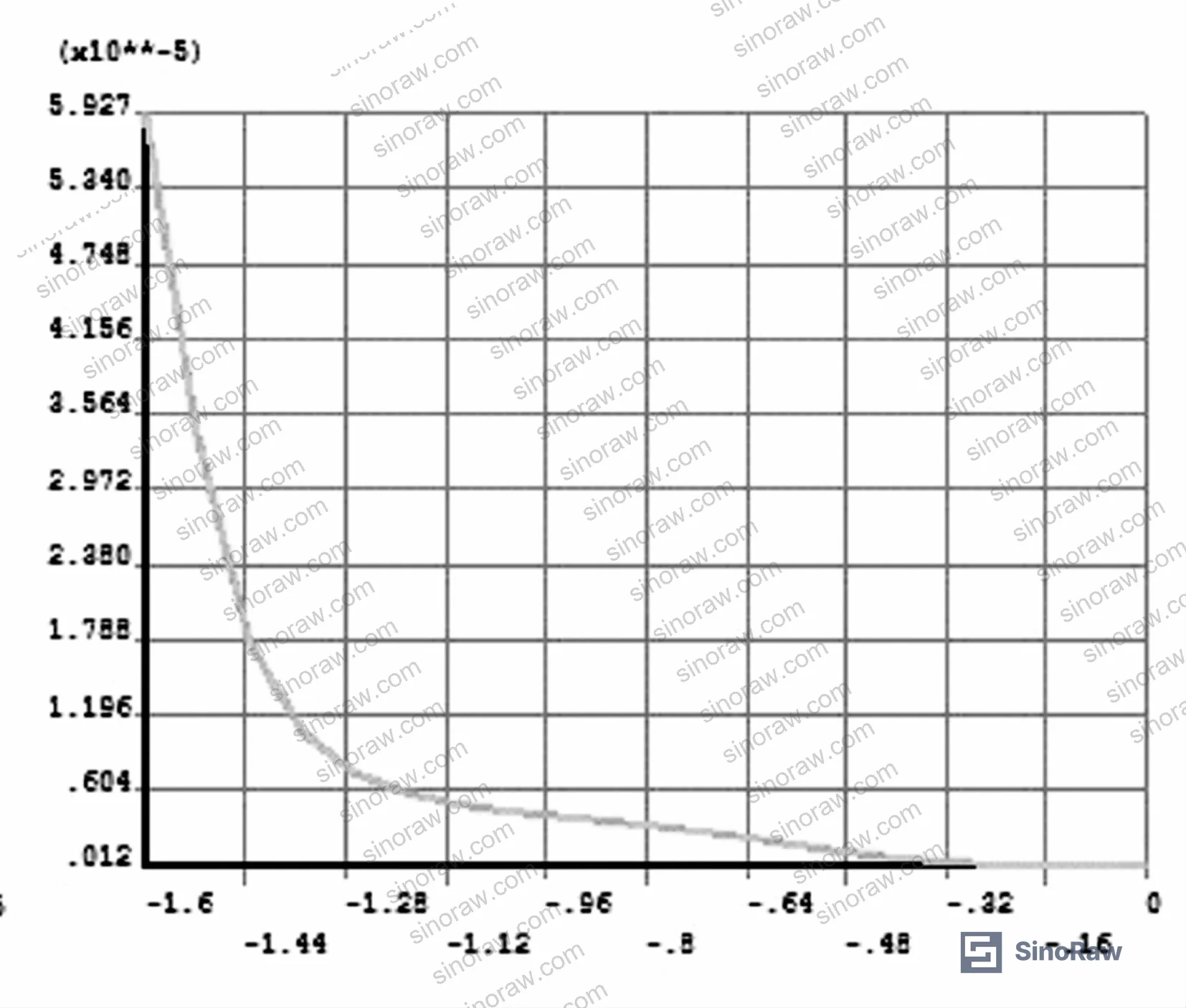
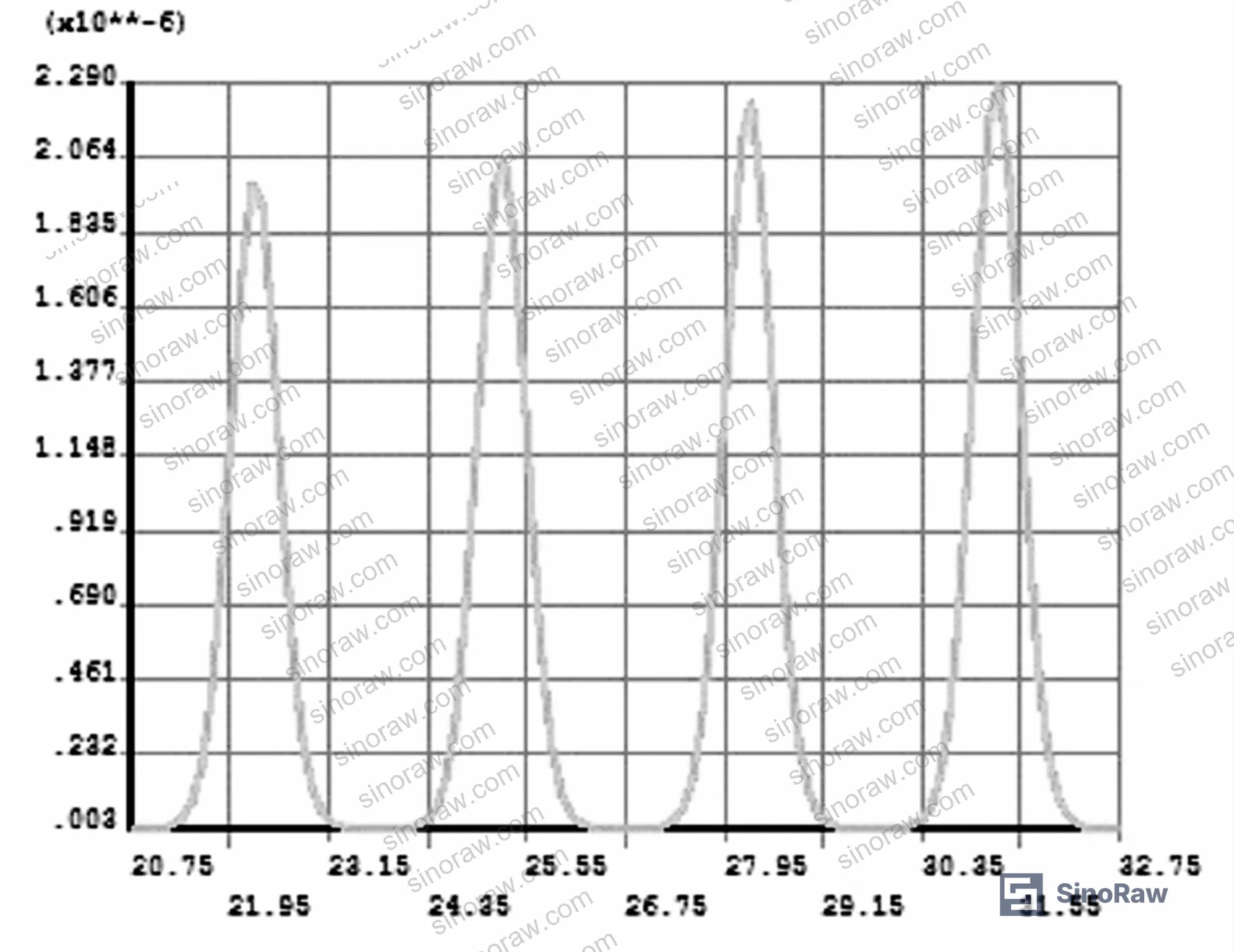
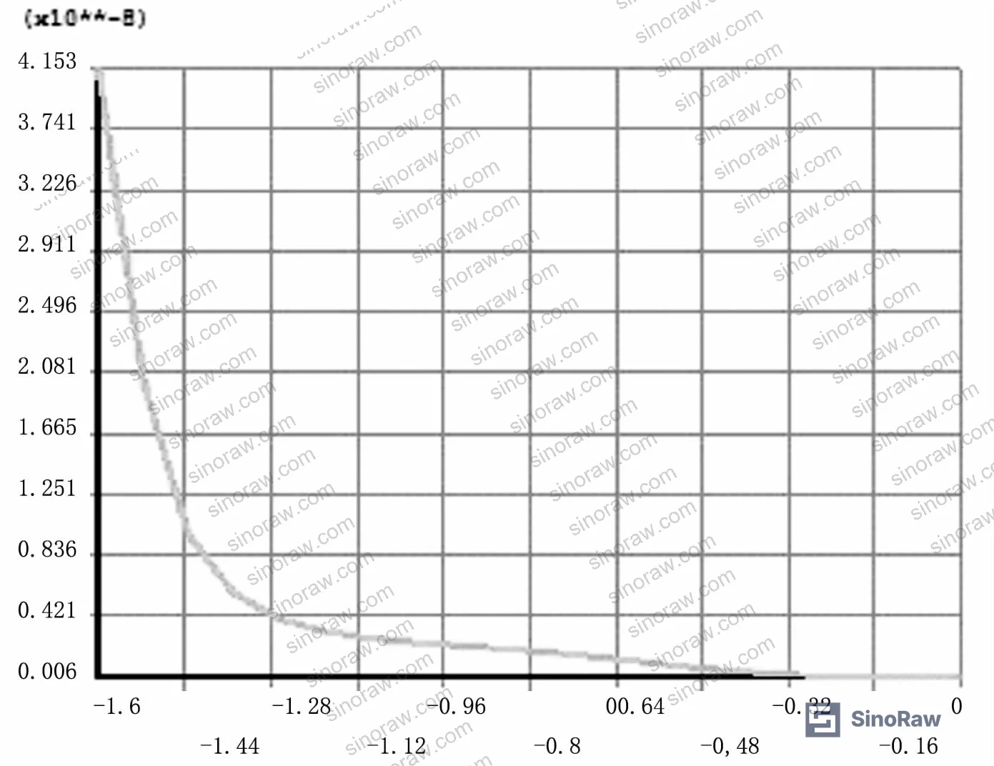
The axial strain profiles — traced from wave trough to tooth tip at all four load levels — show a consistent and steep gradient. Trough-zone creep strain is the maximum at every load condition; tooth-tip strain is the minimum. The numerical gap between these two zones is significant.
At 150 MPa, the surface and axial creep strain distributions show the most dramatically non-uniform profile:
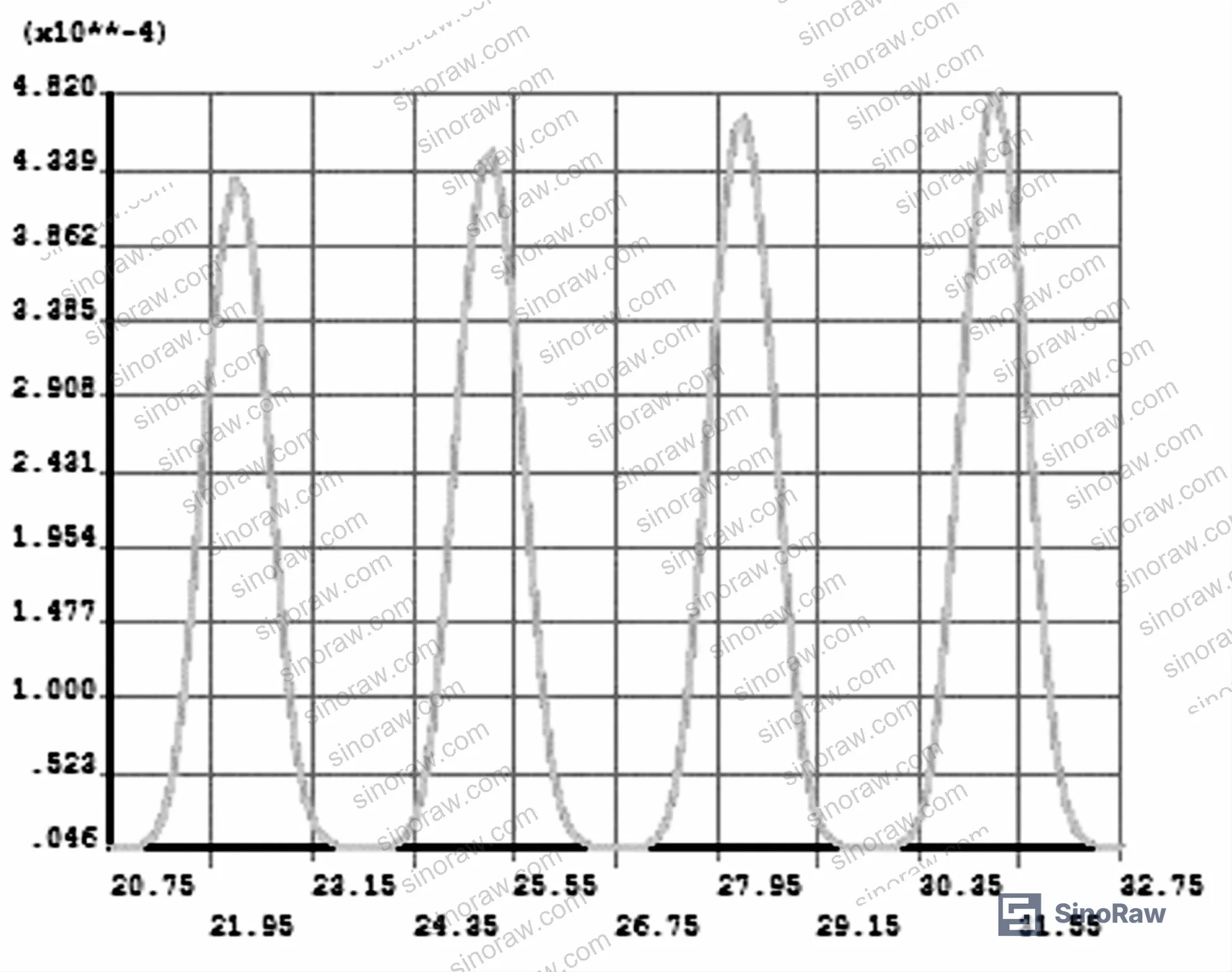
At 100 MPa:
At 70 MPa:
At 45 MPa:
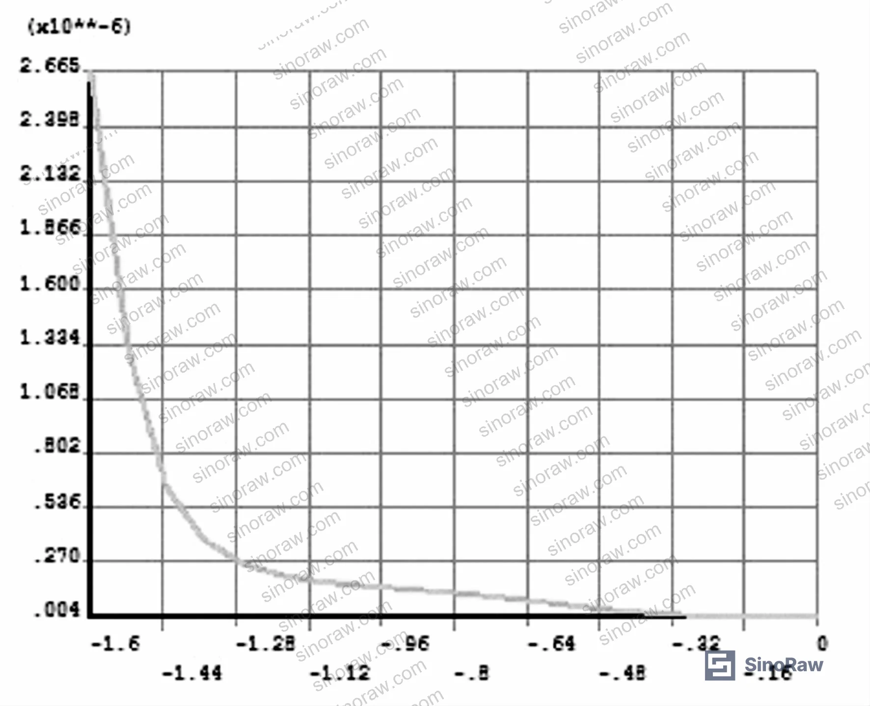
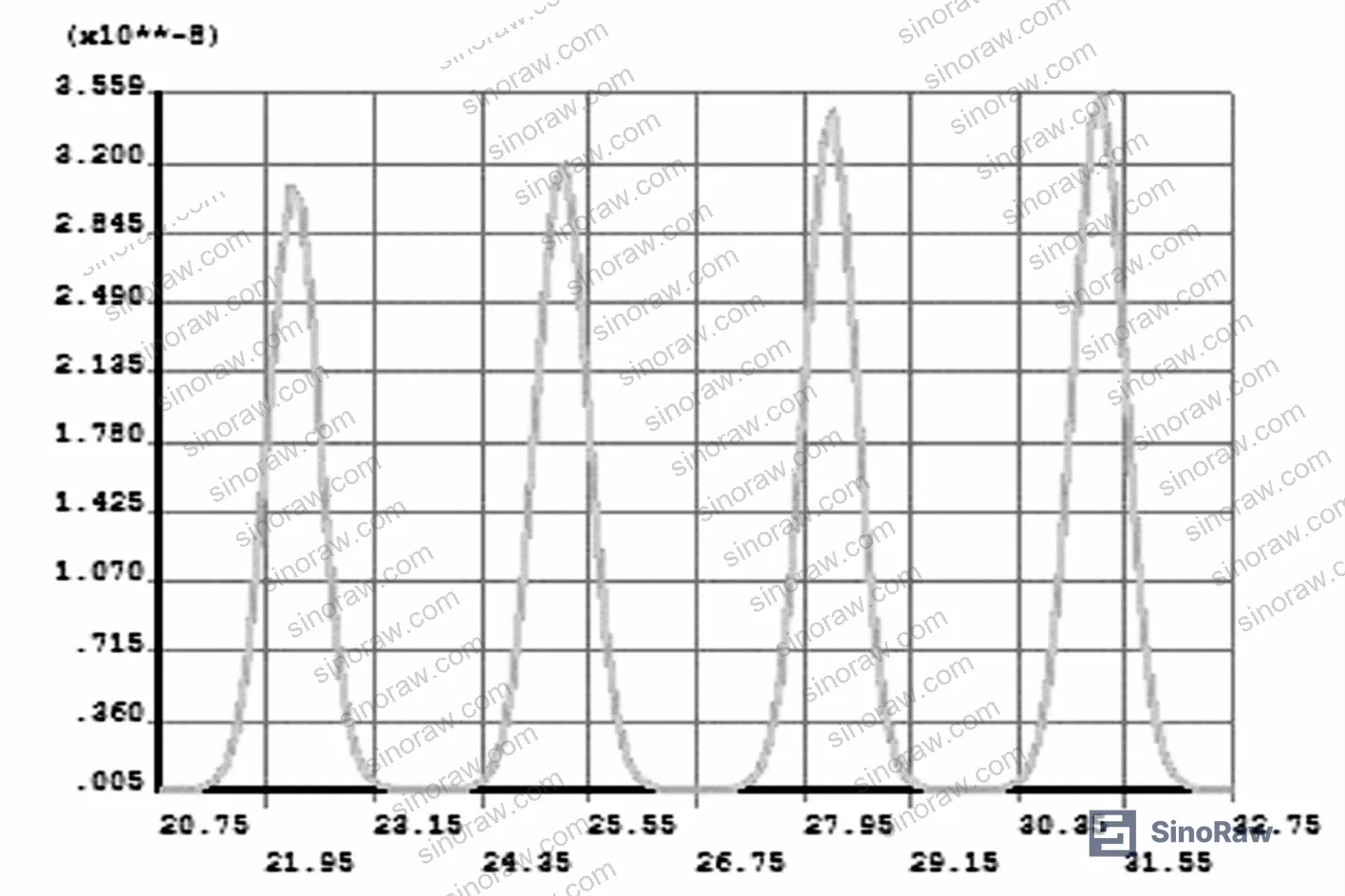
The tooth-tip stress singularity was excluded from the analysis by convention — the FEA model ignored this geometric anomaly, which is standard practice and does not distort the real mechanical behavior of the frame.
Comparison of Creep Strain Behavior Across Load Levels #
| Load Level | Dominant Creep Zone | High-Strain Area Spread | Frame Impact Assessment |
|---|---|---|---|
| 45 MPa | Trough only, localized | Small | Low — minimal structural effect |
| 70 MPa | Trough extending outward | Moderate | Moderate — spreading but contained |
| 100 MPa | Trough + adjacent profile | Significant | High — notable frame degradation risk |
| 150 MPa | Broad trough region, large zone | Substantially enlarged | Very high — exponential damage regime |
Honestly, most procurement teams treat gasket creep as a single-point spec — they check the temperature rating, confirm the material is 304 SS or 316 SS, and move on. What this data shows is that the load regime defines the failure mode more than the material choice does, particularly when operating above 100 MPa in continuous high-temperature service.
Structural Design and Sealing Mechanism of Flexible Graphite Wave-Serrated Gaskets #
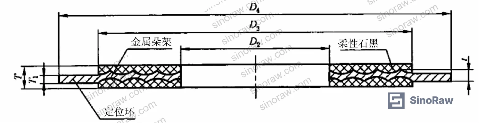
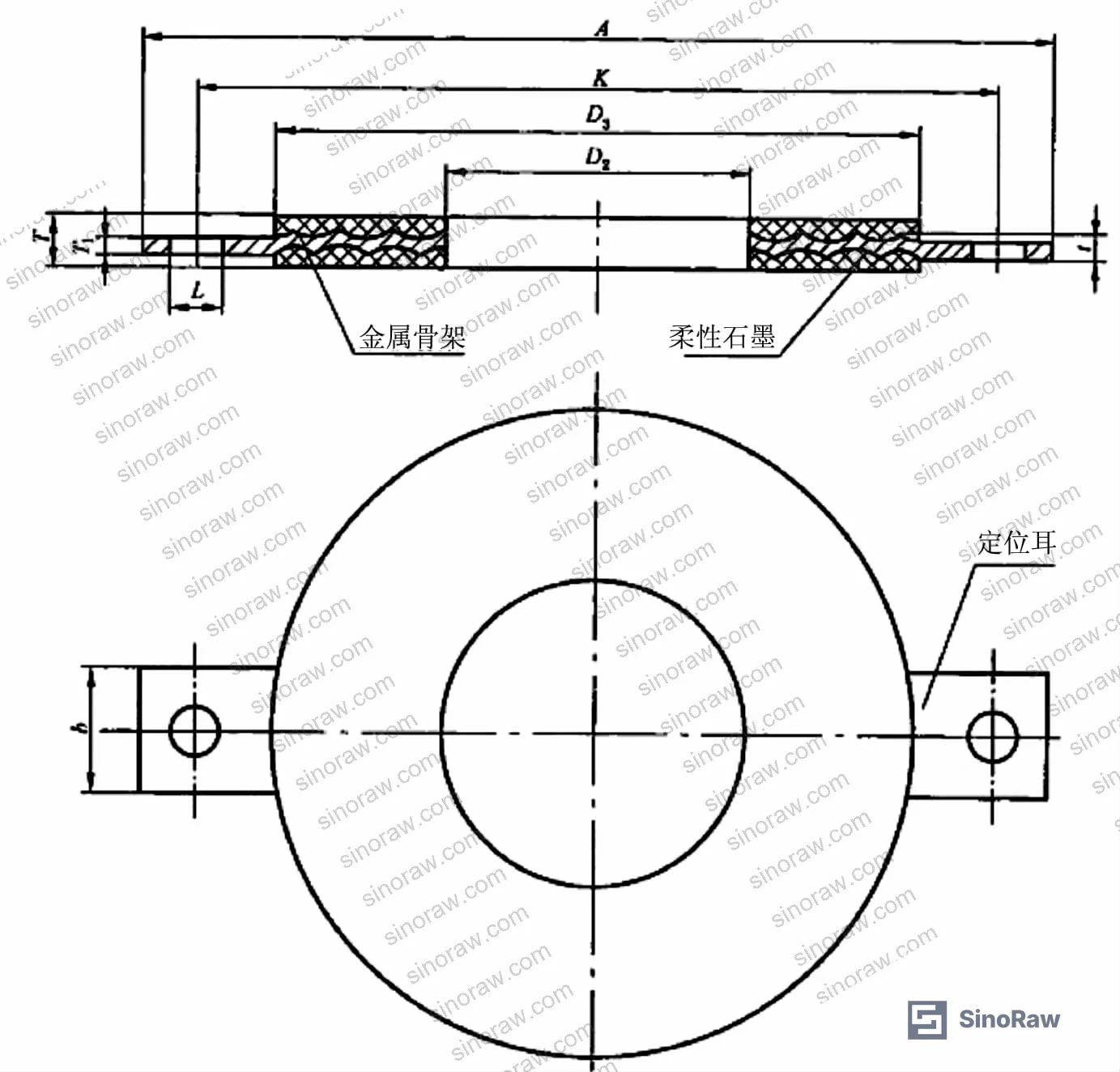
Wave-serrated composite gaskets combine a precision-machined metal backbone with a laminated expanded graphite layer. The metal frame — typically 08, 10, 0Cr13, or 0Cr18Ni9 (304 SS) steel — is machined with concentric arc grooves on both upper and lower surfaces, offset from each other, creating the wave-tooth profile that gives this gasket type its name.
The sealing mechanism is dual-layer: compressed flexible graphite fills micro-defects in the flange sealing face, while the individual tooth crests of the metal frame create discrete line-contact seals against the flange surface. This combination means the graphite handles surface conformance and the metal teeth handle recovery under operating pressure fluctuations. When system pressure rises and the flanges tend to separate, the elastic springback of the wave-profile frame maintains contact pressure — which is precisely why creep damage to the trough zone is dangerous: it degrades this springback reserve over time.
Three structural configurations exist in commercial supply:
- Basic type: suited to tongue-and-groove and male-female flange faces
- Locating ring type: suited to flat-face and raised-face flanges
- Locating lug type: also suited to flat-face and raised-face flanges
Most procurement teams don’t realize that stainless steel frames (0Cr18Ni9/304) show lower compression rates but higher springback rates compared to low-carbon steel frames under equivalent gasket stress. This is not just a metallurgical footnote — it directly affects the minimum required bolt load in your joint design, and undershooting it is the leading cause of early seal relaxation in the field.
Creep-fatigue interaction is a further complication in process plants with cyclic pressure fluctuations. Under combined creep-fatigue loading, gasket life is substantially shorter than a linear summation of creep damage and fatigue damage would predict. The graphite-metal interface adhesive also needs to be evaluated for high-temperature stability — this is an often-overlooked variable in supplier qualification. Compliance with REACH Regulation (EC) No 1907/2006 is relevant here, especially for the adhesive binders used in graphite lamination.
For applications requiring documented quality management processes in manufacturing, verify suppliers against ISO 9001:2015 certification — not as a box-tick, but as a proxy for whether their FEA-supported design process is actually backed by production controls.
Practical Guidance for Buyers #
When you’re evaluating suppliers for flexible graphite wave-serrated gaskets in high-temperature petrochemical or power generation service, the critical specification is not just material grade — it’s the creep behavior of the metal frame under your actual operating bolt load. The simulation data here is clear: below 70 MPa, the frame performs well and the affected zone remains small. Between 70 MPa and 100 MPa, you are entering a transition range where the high-strain zone begins spreading meaningfully. At or above 150 MPa in sustained high-temperature service, you are in a regime where creep effects on the frame are substantial and must be accounted for in maintenance intervals.
Ask for Bailey-Norton creep parameters specific to the frame material and operating temperature. A supplier who can’t provide n and A values for their chosen steel grade at 550°C hasn’t done the engineering. Tooth geometry matters too — the 4-tooth, 0.4 mm tooth depth, 12 mm width configuration in this analysis is a common commercial geometry, but deviations in tooth count or depth change the strain distribution in ways that can either help or hurt depending on load conditions.
At sinoraw.com, our sourcing specialists work with verified Chinese manufacturers of industrial sealing components, helping procurement engineers and plant integrity teams identify suppliers with documented FEA capability and the production controls to back it up. We’re a Guangzhou-based B2B sourcing service — not a manufacturer — and our role is to qualify suppliers before you issue your RFQ, so you’re not finding out about creep failures after installation.
Environmental compliance is also worth noting: expanded graphite used in these gaskets should be verified under RoHS Directive 2011/65/EU where relevant, particularly for applications in European or export-regulated plant environments.
Need help identifying qualified suppliers for flexible graphite wave-serrated gaskets? Talk to our sourcing team →
Supplier Qualification Questions #
- Can you provide Bailey-Norton creep law parameters (n and A values) for your 304 SS / 0Cr18Ni9 frame material at 550°C, and confirm the values are validated against physical test data rather than assumed from published tables?
- At a bolting load of 150 MPa, what is the maximum von Mises creep strain in the wave trough zone of your standard 4-tooth, 0.4 mm tooth depth frame geometry after 10⁵ hours, per your FEA model?
- What is the tooth depth and tooth count per your standard commercial geometry, and do you have FEA-derived creep strain distribution data comparing trough-zone vs. tooth-tip strain at your nominal operating load?
- What is the measured springback rate of your stainless steel frame gasket vs. your low-carbon steel frame gasket under equivalent gasket stress, and how does this inform your minimum recommended bolt load?
- Have you tested or modeled creep-fatigue interaction behavior for applications involving cyclic pressure fluctuation above 100 MPa, and can you provide life prediction data that accounts for combined damage rather than linear summation?
Sourcing Checklist #
- ☐ Supplier has ANSYS or equivalent FEA creep simulation data for their frame geometry, covering at least two load conditions between 45 MPa and 150 MPa at ≥550°C
- ☐ Metal frame material is confirmed as 0Cr18Ni9 (304 SS) or equivalent, with elastic modulus ≥1.49×10⁵ MPa at 550°C per material certification
- ☐ Bailey-Norton creep exponent n is documented for the frame material at operating temperature (reference value: n = 9.4582 for 304 SS at 550°C)
- ☐ Tooth geometry is specified: tooth depth ≥0.4 mm, minimum 4 teeth per profile, single-side width confirmed to ±0.5 mm tolerance
- ☐ Supplier can demonstrate that high-strain creep zone (trough area) remains localized at the specified operating load — i.e., FEA shows no continuous high-strain band across the full cross-section
- ☐ Graphite lamination adhesive has documented high-temperature stability data at the application’s maximum operating temperature
- ☐ Supplier holds ISO 9001:2015 certification covering gasket design, material procurement, and final dimensional inspection
- ☐ Expanded graphite and adhesive materials comply with applicable chemical regulation requirements, with documentation available on request
Key Specifications Table #
| Parameter | Recommended Value | Verification Method |
|---|---|---|
| Frame material elastic modulus at 550°C | ≥1.491×10⁵ MPa | Material cert / supplier FEA input data |
| Bailey-Norton creep exponent (n) for 304 SS at 550°C | 9.4582 | Supplier-provided creep parameter documentation |
| Tooth depth (standard commercial geometry) | 0.4 mm | Dimensional inspection / supplier drawing |
| Single-side gasket width (standard FEA geometry) | 12 mm | Dimensional inspection / supplier drawing |
| Gasket thickness | 2 mm | Calliper measurement per batch inspection |
| Minimum tooth count per profile | 4 teeth | Dimensional / profile inspection |
| Maximum operating load before exponential creep increase | <100 MPa sustained | FEA creep strain curve review |
| Poisson’s ratio (304 SS frame) | 0.3 | Material certification |
Can’t find a supplier meeting these specs? Submit your requirements and we’ll match you within 48 hours.
References #
Data source: Creep Behavior and Strain Distribution of Metal Frames in Flexible Graphite Wave-Serrated Composite Gaskets Under High-Temperature Loading, G.-P. Li et al., Journal of Pressure Vessel Technology, 2025
Frequently Asked Questions #
Where is creep strain highest in a wave-serrated gasket metal frame?
Consistently at the wave trough. FEA simulation across all load cases from 45 MPa to 150 MPa shows the trough zone carries the maximum von Mises creep strain, while the tooth-tip zone carries the minimum. The numerical difference between these two zones is large and increases with load.
Does the creep strain increase linearly with bolting load?
No — and this is the most practically important finding for procurement engineers. Creep strain increases exponentially with load. The jump from 100 MPa to 150 MPa produces a disproportionately larger creep strain and a substantially larger high-strain zone compared to the jump from 45 MPa to 70 MPa. Plan your load margins accordingly.
What steel grades are commonly used for the wave-serrated gasket metal frame?
Commercial options include 08, 10, 0Cr13, and 0Cr18Ni9 (304 SS). The stainless grades show lower compression but higher springback compared to low-carbon steel at equivalent gasket stress. For high-temperature applications above 400°C, 304 SS or higher-alloy grades are standard. See also Pump & Valve Seals for related high-temperature sealing component guidance.
What happens to the gasket at high temperature beyond pure creep?
Three additional failure mechanisms become relevant at elevated temperature: creep relaxation leading to progressive bolt load loss and eventual leakage; accumulated creep damage causing fracture; and creep-fatigue interaction in cyclic pressure service. The last of these is particularly dangerous because the combined damage is not additive — it is worse than the sum of creep and fatigue damage calculated separately. The stability of the graphite-metal adhesive at high temperature is also a practical concern.
How do I verify that a supplier’s gasket geometry matches what was modeled in published creep data?
Request the supplier’s dimensional drawing specifying tooth count, tooth depth, single-side width, and total thickness. Cross-check these against the simulation geometry: 4 teeth, 0.4 mm depth, 12 mm width, 2 mm thickness. Any significant deviation in tooth depth or count changes the creep strain distribution and means published data doesn’t directly apply to the supplier’s product.
Published by sinoraw.com Technical Team | Request a sourcing quote


