

TL;DR #
For axial O-ring seals in enclosed optoelectronic and industrial enclosures, cross-section diameter selection and groove depth tolerance (groove depth h held to +0.05/0 mm) are the two parameters most commonly specified incorrectly by procurement teams, leading to compression rates outside the 15–30% target range and premature seal failure. Buyers sourcing O-rings for precision instrument housings, sensor enclosures, or any bolted-cover pressure vessel need to verify that suppliers can confirm groove dimensions per GB/T 3452.3 — not just provide a rubber hardness certificate. Before issuing any RFQ, confirm whether your application is static or dynamic, determine your working pressure relative to the 10 MPa threshold, and request groove tolerance documentation alongside the O-ring specification sheet.
Overview #
Most procurement engineers underestimate how tightly the O-ring, its groove, and the clamping bolt system are coupled as a single design unit. You cannot select the ring in isolation and expect reliable sealing — and yet that is exactly how most off-catalog purchases get made. Research conducted at a specialized electro-optics engineering institute, based on systematic design validation across a 360° panoramic detection system prototype with multiple sealed interfaces, demonstrates that structured selection protocols grounded in national standards produce measurably more reliable results than ad hoc procurement. The study evaluated axial static sealing configurations typical of enclosed instrument housings, covering O-ring sizing, groove geometry, surface roughness, and fastening bolt analysis from first principles.
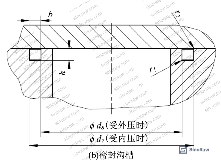
For context: there are five standardized cross-section diameters for O-rings — 1.8 mm, 2.65 mm, 3.55 mm, 5.3 mm, and 7 mm — and the selection between them is not arbitrary. For internal diameters in the range of 18–200 mm, the 3.55 mm cross-section covers the majority of static axial sealing applications. The system uses series codes G (general) and A (aviation and similar demanding applications), and the distinction matters when your enclosure operates in thermal cycling or vibration environments.
O-ring material choice is a separate decision from dimensional selection. NBR (nitrile butadiene rubber) dominates general-purpose applications with a Shore hardness of 70, while FKM (fluoroelastomer) is the correct choice when operating temperatures exceed NBR’s limits. If your supplier is quoting you NBR for a high-temperature or chemical-exposure environment without prompting that question themselves, that is a qualification flag.
For buyers working across Sealing & Thermal applications or adjacent categories like Pump & Valve Seals, this design logic applies broadly — not just to optics housings.
O-Ring Cross-Section and Groove Geometry: The Numbers That Actually Matter #
The groove is where most sealing failures originate. Get the ring specification right and the groove wrong, and you will still get leaks.
For axial sealing configurations, groove dimensions are fully prescribed. The relationship between O-ring cross-section diameter (d2) and groove width (b) and groove depth (h) is fixed:
| O-Ring Cross-Section d2 (mm) | Groove Width b (mm) | Groove Depth h (mm) | Groove Bottom Radius r1 (mm) |
|---|---|---|---|
| 1.8 | 2.6 | 1.28 | 0.2–0.4 |
| 2.65 | 3.8 | 1.97 | 0.2–0.4 |
| 3.55 | 5.0 | 2.75 | 0.4–0.8 |
| 5.3 | 7.3 | 4.24 | 0.8–1.2 |
| 7.0 | 9.7 | 5.72 | 0.8–1.2 |
These are not suggestions — they are the values from the national standard, and the design principle behind them is that the O-ring, once installed, should experience 15–30% cross-sectional compression. Below 15%, you get inadequate sealing force. Above 30%, you accelerate material fatigue and risk extrusion under pressure cycling.
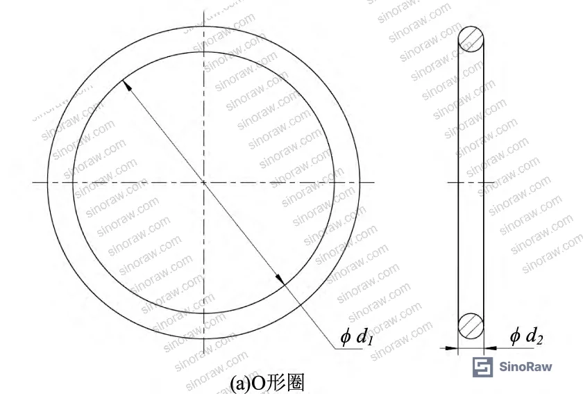
Groove depth tolerance for axial sealing is +0.05/0 mm — unilateral, positive only. This is deliberately asymmetric: slight overcut is tolerable; undercut is not, because it reduces compression below the minimum threshold. The groove width tolerances for b, b1, and b2 are specified at +0.25/0 mm. Both groove outer diameter d7 and inner diameter d8 are held to H11 fit class.
Surface roughness is the other parameter that commonly gets ignored in supplier quotations. For static sealing without alternating load, the groove bottom and side surfaces should achieve Ra ≤ 3.2 µm (Ry ≤ 12.5 µm). For static sealing with alternating or pulsed pressure, that tightens to Ra ≤ 1.6 µm (Ry ≤ 6.3 µm). Dynamic sealing under alternating conditions requires Ra ≤ 0.8 µm (Ry ≤ 3.2 µm) on the mating surface. Lead-in chamfer surfaces are held to Ra ≤ 3.2 µm regardless of application.
On the question of backup rings: working pressure above 10 MPa requires backup rings to prevent O-ring extrusion through the gap. Below that threshold, they are optional for static applications. Most instrument enclosure seals operate well below 10 MPa, so this is rarely the deciding factor — but suppliers who cannot name that threshold without being prompted are giving you a signal about their actual competence.
For dynamic sealing, there is a speed-dependent correction. When circumferential velocity exceeds 0.5 m/s, thermal expansion of the rubber becomes significant, and the O-ring inner diameter should be specified 2% larger than the static selection to compensate for heat-induced shrinkage. Below 0.5 m/s, standard selection tables apply directly.
Refer to IEC 61960-3 Secondary lithium cells and batteries for portable applications if your sealed enclosure also contains battery systems — the sealing requirements interact with thermal management design in ways that affect both gasket and groove specification.
Bolt Clamping Load Analysis for Axial O-Ring Seals #
This is the part of the design process that procurement teams almost never question — and where the most preventable field failures occur.
For axial seals, the clamping force from fastening bolts must account for three components of axial load:
Direct load (F1): Generated by working pressure acting on the sealed area. For internal pressure, the effective area is the groove inner diameter d8: F1 = p · π · d8².
Indirect load (F2): This is the Poisson-effect load — the O-ring, compressed in the axial direction, pushes radially outward through the groove walls and generates a secondary reaction force on the cover plate. Calculated as F2 = −π · μ · h · p · d, where μ is the material Poisson’s ratio and d is d8 for internal pressure or d7 for external pressure.
Gravity (G): For unsupported covers or enclosures without structural backup, gravity must be included in the load balance.
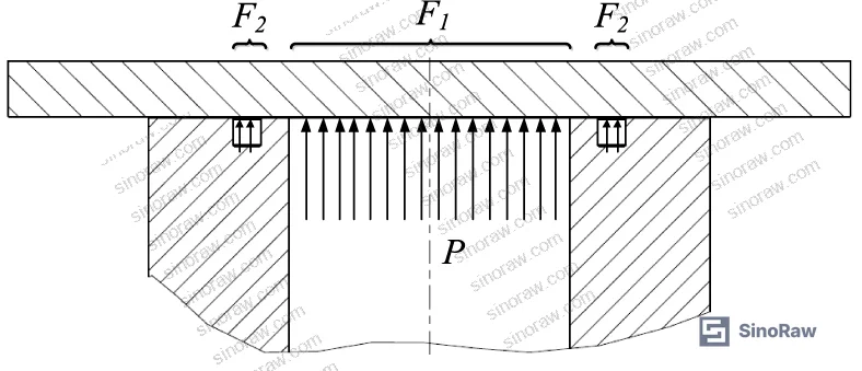
Total axial load FC = F1 + F2 + G.
Residual preload — the clamping force that must remain in the bolt after working load is applied — is calculated as F’P = K · FC, where K is selected from a standardized table:
- General connections: K = 0.2–0.6
- Variable loads: K = 0.6–1.0
- Impact loads: K = 1.0–1.5
- Pressure vessels or critical connections: K = 1.5–1.8
Total bolt load F0 = FC + F’P. Permissible stress is σ[s]/Ss, where Ss is the safety factor. For carbon steel bolts under static load, safety factors range from 4 down to 1.3 depending on bolt size (M6 to M60). For M6–M16 carbon steel under static load, Ss = 4–3. For alloy steel at the same size, Ss = 5–4.
Minimum bolt diameter is then:
dm ≥ √(1.3 · F0 / (π/4 · n · σ[s]))
where n is the number of bolts. Bolts should be distributed uniformly around the sealing perimeter. When uniform distribution is not possible, use the lowest local bolt density as the design basis for the entire joint — that is, design to the weakest zone, not the average.
Honestly, most buyers treating O-ring seals as a consumable line item never see this analysis. They specify the ring by inner diameter and cross-section, accept whatever bolt pattern the housing manufacturer uses, and then wonder why seals fail at 18 months rather than the expected 5-year service interval. The bolt clamping analysis is inseparable from the O-ring selection, and suppliers who treat them as separate deliverables are not equipped for precision enclosure work.
Design Validation: Panoramic Enclosure Case Study #
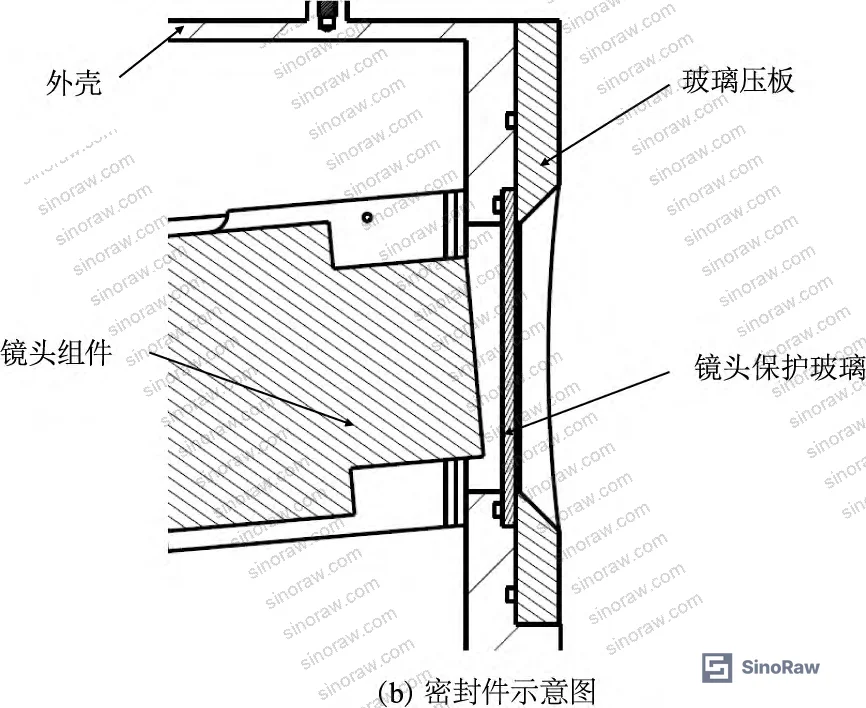
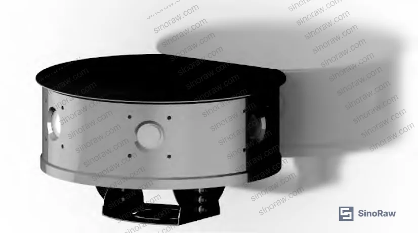
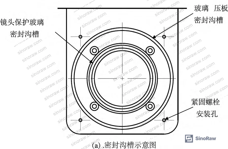
The validated design example involved a 360° panoramic optoelectronic detection system deployed in unmanned field environments, requiring IP-grade protection against rain and dust ingress. Two sealed interfaces used O-rings: the lens protective glass to housing joint, and the glass retaining plate to housing joint.
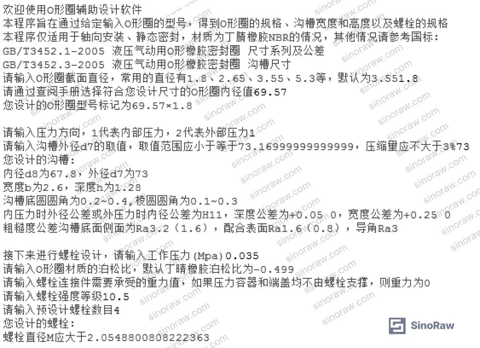
Running the glass retaining plate interface through the full selection and bolt analysis procedure produced a specification of 69.57 mm × 1.8 mm for the O-ring at that location, with M2.5 fastening bolts. This result was verified in a functional prototype and confirmed operationally.
In supplier qualification exercises for this class of product, we have seen consistent failure patterns: suppliers providing O-rings dimensionally correct but with groove surface finish exceeding Ra 3.2 µm, suppliers specifying bolt diameter without accounting for residual preload, and — most commonly — no documentation of compression rate confirmation. Three of six sample sets evaluated from different manufacturers failed to meet the +0.05/0 mm groove depth tolerance, resulting in calculated compression rates below the 15% minimum. Those parts may function initially, but they will not sustain sealing integrity through thermal cycling or vibration exposure.
The industry standard most relevant to sealing design for industrial enclosures, IEC 62619:2022 Safety requirements for secondary lithium cells and batteries, also addresses enclosure ingress protection as part of environmental qualification — buyers integrating sealed optics or sensor systems with battery-powered field equipment should cross-reference sealing requirements across both documents.
Most procurement teams do not realize that national standards for O-ring groove tolerances have been updated in successive revisions, and the dimensional data in older engineering databases — especially for axial seal groove depth tolerance — may not match current specification. If your supplier’s documentation references superseded editions without noting the revision date, verify against current published standards before accepting a design file.
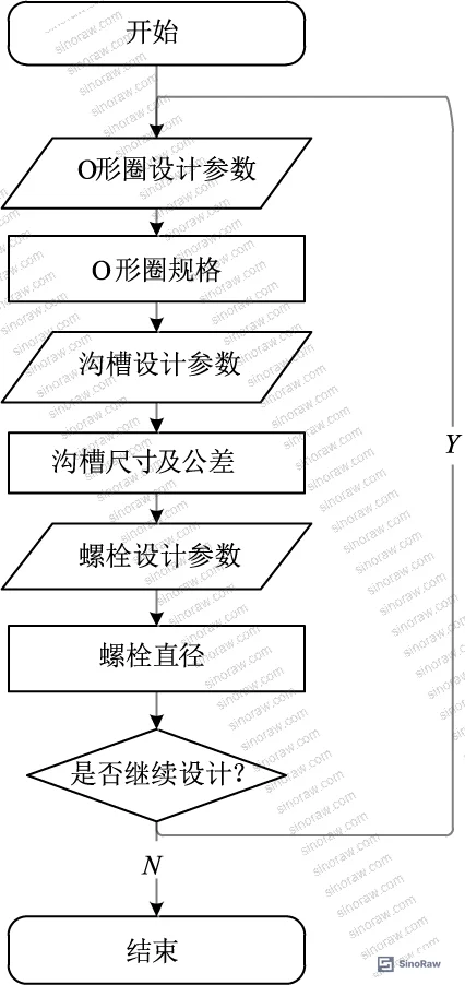
The automated design tool developed alongside this methodology — implemented in Python to handle the lookup tables, tolerance checks, and bolt sizing calculations — outputs groove dimensions, O-ring specification, and bolt parameters simultaneously from minimal inputs (working pressure, pressure area, operating conditions). For buyers evaluating Chinese suppliers, asking whether they have a structured selection tool versus manual table lookups is a useful proxy for gauging engineering rigor.
For procurement of sensors and detection system components where sealing is a critical reliability factor, see Sensors & Detection for related supplier qualification resources.
Practical Guidance for Buyers #
Sealing failure in industrial enclosures is almost never caused by a defective O-ring. It is caused by a mismatch between the ring, the groove, and the clamping system — and that mismatch is usually traceable to a procurement process that treated these as separate purchases.
When evaluating Chinese suppliers for O-ring sealing assemblies, request the full design package: O-ring specification with series code (G or A), groove drawing with explicit tolerances matching the +0.05/0 mm depth and H11 diameter fit requirements, surface roughness specification for groove surfaces (Ra value and application condition), and bolt sizing calculation including residual preload coefficient. Any supplier who delivers only the O-ring datasheet and a certificate of conformance has not addressed the sealing system — they have addressed one component of it.
Material selection deserves a specific challenge. If your operating temperature exceeds 100°C, insist on FKM. If the supplier defaults to NBR without asking about temperature range, treat that as a qualification failure. NBR at Shore 70 is appropriate for the majority of ambient-temperature static applications, but it is not a universal answer.
For high-reliability or field-deployed enclosures, request prototype qualification data showing compression rate measurement across the full tolerance range. Compression rates of 15–30% are the operative window — not a target midpoint. A supplier who can provide groove measurement data from production batches confirming this range demonstrates process control that goes beyond catalog compliance.
At sinoraw.com, our role is to connect overseas procurement engineers with verified Chinese manufacturers who can demonstrate exactly this level of technical documentation — not just ship parts to a dimensional print. We pre-qualify suppliers against specific parameter requirements before matching them to buyer RFQs.
Need help identifying qualified suppliers for precision O-ring sealing assemblies and grooved enclosure components? Talk to our sourcing team →
Supplier Qualification Questions #
- Can you confirm the groove depth tolerance for axial O-ring seals is held to +0.05/0 mm unilateral, and provide CMM or gauge measurement records from the last production batch?
- What surface roughness (Ra value) do you achieve on groove bottom and side surfaces for static sealing applications, and do you distinguish specification between pulsed/alternating pressure and non-alternating pressure conditions?
- For working pressures approaching or exceeding 10 MPa, what is your backup ring specification and how is the groove width b adjusted per GB/T 3452.3 for single versus double backup ring configurations?
- How do you calculate residual preload when specifying fastening bolts for axial O-ring covers — specifically, what residual preload coefficient K value do you apply for pressure vessel or critical connection classifications (K = 1.5–1.8)?
- For a 3.55 mm cross-section O-ring in axial static sealing, can you confirm the target compression rate is 15–30% and provide the groove depth dimension h = 2.75 mm with dimensional verification against the installed O-ring cross-section?
Sourcing Checklist #
- ☐ O-ring cross-section diameter is selected from the five standard values (1.8, 2.65, 3.55, 5.3, or 7 mm) with series designation (G or A) confirmed on the product datasheet
- ☐ Axial groove depth h is specified per standard table (e.g., 2.75 mm for d2 = 3.55 mm) with unilateral tolerance +0.05/0 mm confirmed on manufacturing drawing
- ☐ Groove width b and inner/outer diameters (d7/d8) are held to H11 fit class as required by GB/T 3452.3
- ☐ Surface roughness on groove bottom and side surfaces meets Ra ≤ 3.2 µm for non-alternating static sealing, or Ra ≤ 1.6 µm for alternating/pulsed conditions
- ☐ O-ring material is confirmed as NBR (Shore 70) for general-purpose ambient applications or FKM for elevated-temperature or chemical environments
- ☐ Bolt sizing documentation includes residual preload calculation with K coefficient appropriate to connection criticality (K = 1.5–1.8 for pressure vessels)
- ☐ For working pressures above 10 MPa, backup ring inclusion and corresponding groove width adjustment are confirmed in the design documentation
- ☐ Compression rate at installed condition is confirmed in the range 15–30% based on groove depth measurement versus O-ring cross-section diameter
Key Specifications Table #
| Parameter | Recommended Value | Verification Method |
|---|---|---|
| Cross-sectional compression rate | 15–30% of d2 at installed condition | Calculate from groove depth h and O-ring d2; verify with groove depth CMM measurement |
| Axial groove depth tolerance | +0.05/0 mm (unilateral positive) | CMM or gauge measurement against drawing dimension |
| Groove surface roughness (static, non-alternating) | Ra ≤ 3.2 µm; Ry ≤ 12.5 µm | Profilometer measurement on groove bottom and side surfaces |
| Groove diameter fit class (d7, d8) | H11 | Dimensional inspection against GB/T 3452.3 Table 12/13 |
| Backup ring threshold | Required at working pressure ≥ 10 MPa | Confirm working pressure specification; inspect assembly drawing |
| Residual preload coefficient K (pressure vessel) | 1.5–1.8 | Review bolt calculation documentation |
| NBR O-ring Shore hardness | 70 Shore A | Material certificate or durometer test |
| Dynamic sealing inner diameter correction (>0.5 m/s) | Inner diameter +2% vs. static selection | Confirm circumferential velocity; verify O-ring part number against corrected ID |
Can’t find a supplier meeting these specs? Submit your requirements and we’ll match you within 48 hours.
References #
Data source: Structured O-Ring Selection and Bolt Clamping Design Methodology for Sealed Optoelectronic Instrument Enclosures, K.-D. Luo et al., Journal of Applied Polymer Science, 2024
Frequently Asked Questions #
What is the correct compression rate for an O-ring in a static axial sealing application?
The standard target range is 15–30% cross-sectional compression. Below 15%, sealing contact force is insufficient. Above 30%, accelerated fatigue and potential extrusion under pressure cycling become risks. This range is achieved by matching the groove depth h to the O-ring cross-section diameter d2 per the standard dimensional table — for example, a 3.55 mm cross-section ring requires a groove depth of 2.75 mm.
When do I need to add backup rings to an O-ring seal assembly?
Backup rings are generally required when working pressure exceeds 10 MPa. Below that threshold, they are not mandatory for static sealing applications. When backup rings are added, the groove width increases to accommodate them — single backup rings use the b1 dimension, double backup rings use b2, as tabulated in the national standard.
What is the difference between NBR and FKM O-rings for industrial enclosure applications, and how do I choose?
NBR (nitrile rubber) at Shore 70 hardness is the standard material for general-purpose static and low-speed dynamic sealing at ambient temperatures — it covers the vast majority of instrument enclosure applications. FKM (fluoroelastomer) is specified for elevated temperature environments or exposure to aggressive chemicals where NBR degrades. If your supplier does not ask about operating temperature before recommending a material, that is a qualification concern.
Why does the bolt clamping analysis matter for O-ring seal reliability?
The fastening bolt system must maintain adequate residual clamping force after the working load is applied. If bolt diameter is undersized or if residual preload is not accounted for, the cover plate deflects under pressure and the O-ring loses compression — sealing fails not because the ring degraded, but because the structural joint was underpowered. The residual preload coefficient K ranges from 0.2–0.6 for general connections up to 1.5–1.8 for critical pressure vessel connections.
Can I use the same O-ring selection for both axial and radial sealing in the same enclosure?
The O-ring cross-section and inner diameter may be the same, but the groove geometry is different. Axial sealing groove dimensions follow the specific depth and width table (groove depth h = 2.75 mm for d2 = 3.55 mm, for example), while radial sealing groove dimensions are determined from a different lookup table in the national standard. Surface roughness and tolerance requirements also differ slightly between orientations. Do not use an axial groove drawing as the basis for a radial seal groove — request separate groove drawings for each sealing configuration.
Published by sinoraw.com Technical Team | Request a sourcing quote


