

TL;DR #
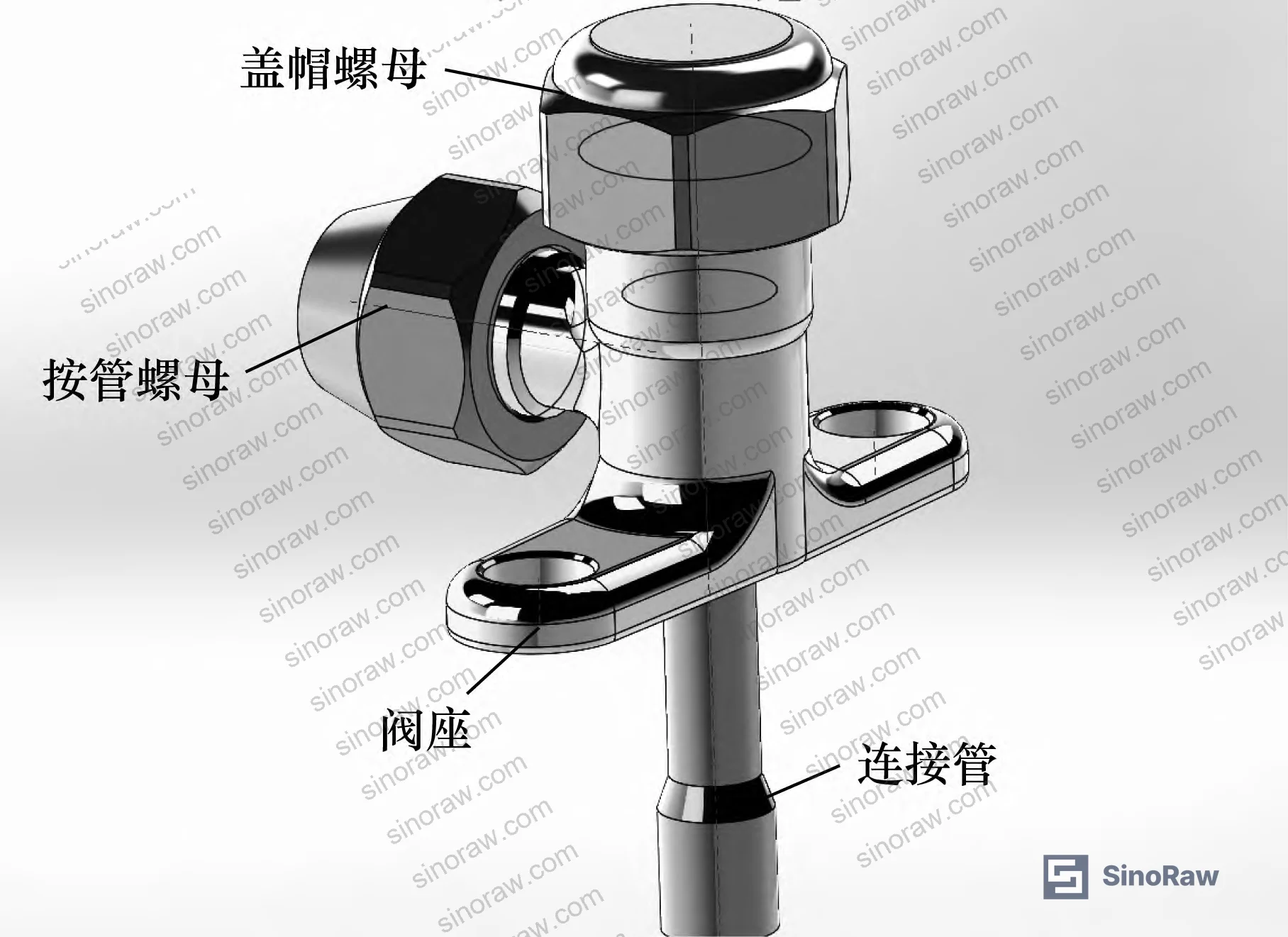
FEA simulation validated against physical torque tests confirms that a copper globe valve with 1.5 mm minimum wall thickness reaches its yield strength (130 MPa) at a cap nut tightening torque of 28.8 N·m — comfortably above the JB/T 10648—2017 standard requirement of 20–25 N·m, but with far less margin than most buyers assume. If a supplier’s wall thickness falls even fractionally below spec, that safety margin collapses during field installation and you end up with a structurally failed valve body on-site. Before issuing an RFQ, require FEA-backed wall thickness validation data from any supplier claiming JB/T 10648—2017 compliance.
Overview #
Copper globe valves for refrigerant service are one of those components where procurement teams routinely treat dimensional compliance as a proxy for structural integrity — and that assumption will cost you eventually. The critical question isn’t whether the wall thickness meets the drawing nominal; it’s whether the minimum wall thickness, at the exact location where the cap nut thread engages, can withstand installation torque without yielding.
The data presented here comes from a combined FEA simulation and physical test program conducted by an HVAC valve engineering team at a major Chinese refrigeration components manufacturer, in collaboration with a university energy engineering faculty. The study modeled a 4 mm nominal bore copper globe valve (leaded brass, C3771 alloy) using a nonlinear FEA solver, then physically validated the simulation results by measuring connector angular deflection on four production samples under applied torque up to 80 N·m. Simulation-to-test deviation across all four samples fell within 2.80% — well inside the ±5% engineering acceptance threshold. That level of agreement gives the torque-stress relationship real credibility for procurement specification purposes.
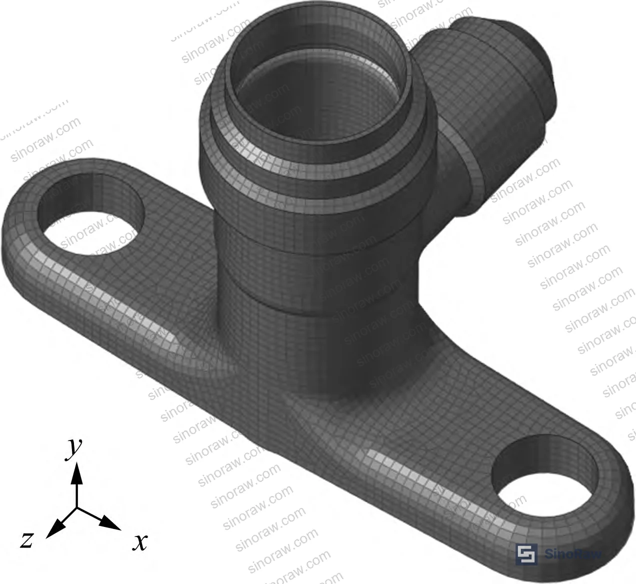
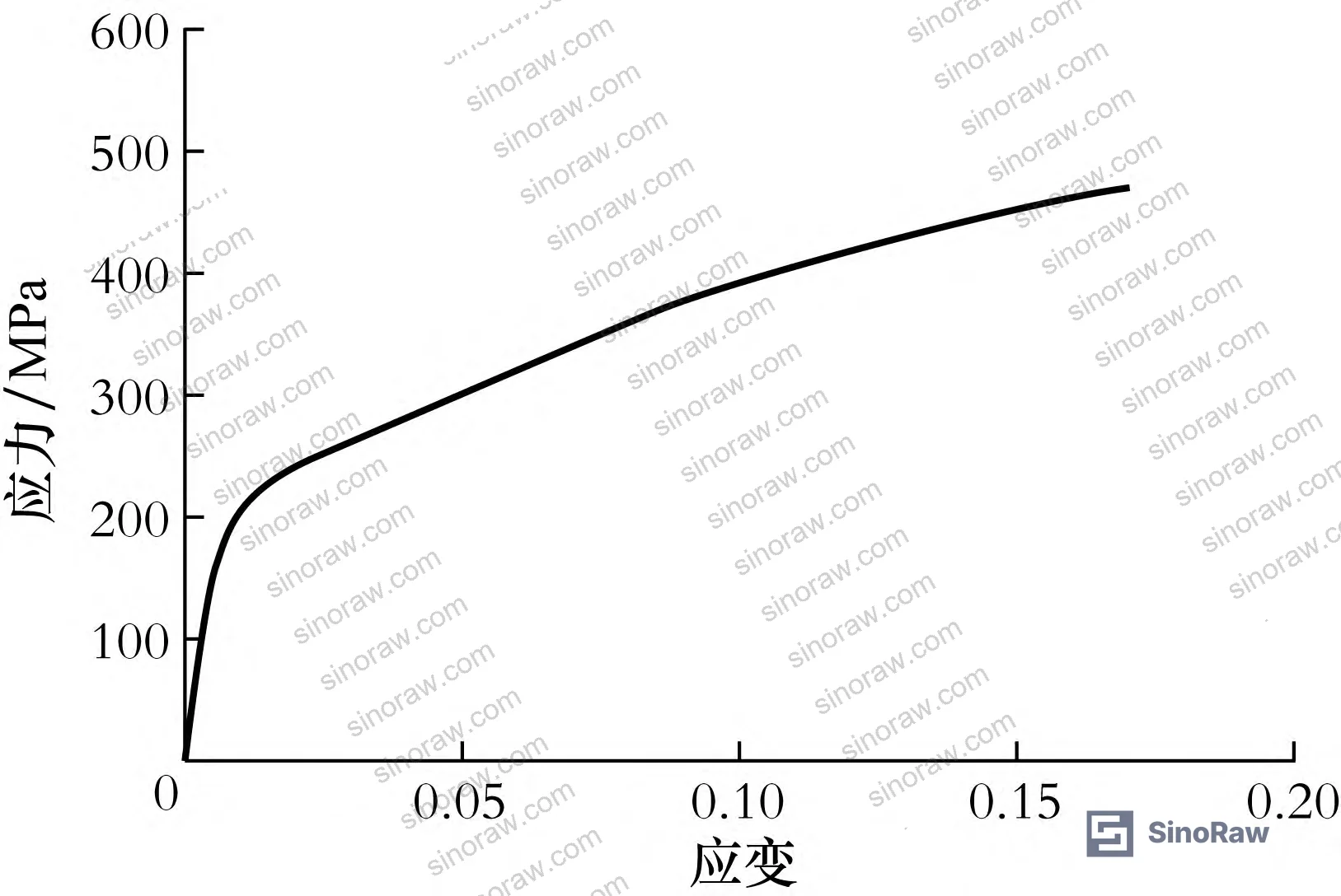
The valve body is leaded brass C3771 with a Young’s modulus of 105 GPa, Poisson’s ratio of 0.3, yield strength of 130 MPa, and tensile strength of 557.3 MPa. These aren’t estimates — they’re the material property inputs that the FEA model was calibrated against, and they define the two critical torque thresholds that every buyer specifying these valves should know.
For buyers sourcing Pump & Valve Seals or adjacent fluid control components from Chinese manufacturers, this analysis provides something rare: a quantified, experimentally verified link between a geometric tolerance (minimum wall thickness) and a field failure mode (valve body fracture during installation).
Tightening Torque Limits and Minimum Wall Thickness in Copper Globe Valves #
This is where the numbers matter most, and where most RFQ specifications miss the critical detail.
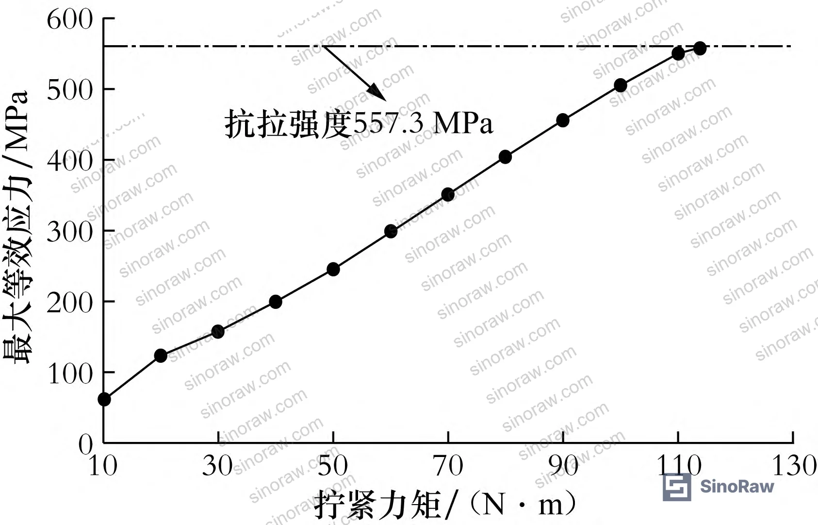
The simulation swept cap nut tightening torque from 16 N·m upward in 1 N·m increments while monitoring maximum von Mises equivalent stress at the minimum wall thickness location (1.5 mm wall, cap nut end). The stress response is nonlinear — it rises on a curve, not a straight line — which means intuitive extrapolation from one data point will mislead you.
Key stress progression data points from the simulation:
- At 16 N·m: maximum equivalent stress = 98.22 MPa (below yield)
- At 22 N·m: maximum equivalent stress = 130.3 MPa (approximately at yield — 130 MPa)
- At 28 N·m: maximum equivalent stress = 146.2 MPa (plastic zone developing)
- At 32 N·m: maximum equivalent stress = 166.6 MPa (significant plastic deformation)
The yield-limit torque, calculated from the FEA step-time analysis, is 28.8 N·m. This is the upper bound for installation torque without causing permanent deformation to the valve body at the minimum wall location.
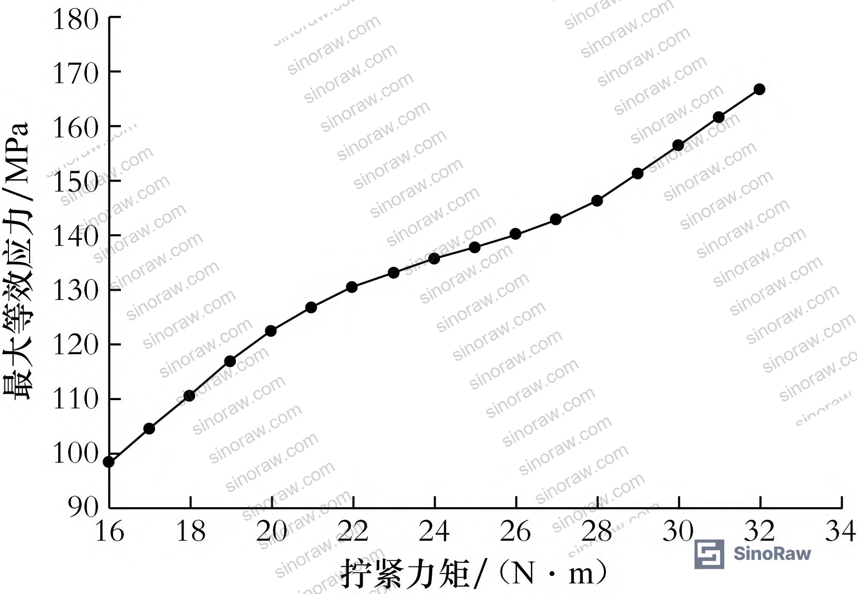
The second critical threshold — where stress reaches the material’s ultimate tensile strength of 557.3 MPa — occurs at 113.7 N·m. Beyond this point, the valve body fails catastrophically. In a field installation context, this can happen if an inexperienced technician uses a high-torque impact tool without a torque limit, or if the actual wall thickness is undersized and the effective yield point is shifted downward.
Honestly, most procurement specs I’ve reviewed for this valve category only cite the JB/T 10648—2017 torque range (20–25 N·m for this bore size) without demanding any evidence that the supplier’s wall thickness design provides adequate margin above that range. The 28.8 N·m yield threshold gives you only 3.8 N·m of margin over the upper end of the standard requirement. That’s not a lot if a technician is slightly heavy-handed.
| Tightening Torque (N·m) | Max Equivalent Stress at Min. Wall (MPa) | Structural Condition |
|---|---|---|
| 16 | 98.22 | Fully elastic, no yield |
| 22 | 130.3 | At yield strength threshold |
| 28 | 146.2 | Plastic deformation onset |
| 28.8 | ~150.1 (step time 0.900) | Yield limit — JB/T 10648 max allowable |
| 32 | 166.6 | Post-yield, permanent damage |
| 113.7 | 557.3 | Tensile failure — valve body fracture |
FEA Model Validation: Test Method and Results #
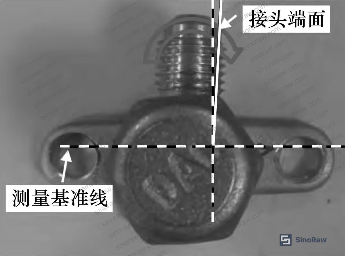
The simulation was validated using a torque wrench (model DB200N-S, range 20–200 N·m, minimum graduation 2 N·m) and an optical projector (Easson imaging system, resolution 0.01 μm, repeatability ±2 μm, max load capacity 25 kg).
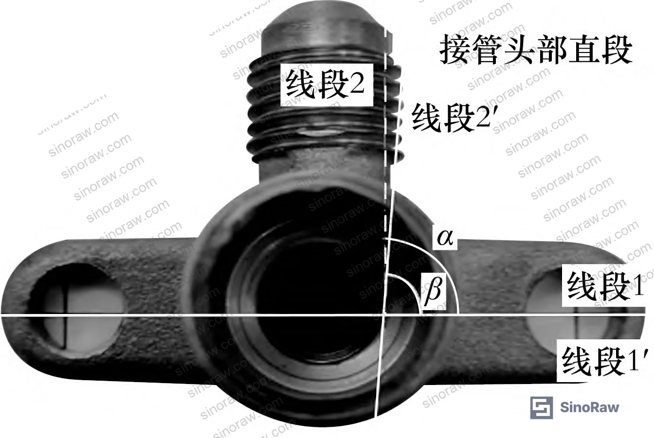
The test approach measured angular deflection of the connector head relative to the valve seat mounting face — before and after torque application. Direct surface deformation measurement was rejected because parting line irregularities after deformation introduce unacceptable measurement error. The angle-change method using the connector’s linear edge segment as a reference proved far more repeatable.
Four production samples were tested at 80 N·m (the test ceiling — above 80 N·m, thread strip-out was observed on the cap nut). Simulation predicted a connector deflection angle δ = 2.61° (derived from a simulated post-deformation angle of 87.39° vs. the theoretical 90°).
Physical test results across four samples:
| Sample | Pre-test angle α (°) | Post-test angle β (°) | Measured deflection γ (°) | FEA predicted δ (°) | Error (%) |
|---|---|---|---|---|---|
| 1 | 90.95 | 88.41 | 2.54 | 2.61 | 2.68 |
| 2 | 91.37 | 88.81 | 2.56 | 2.61 | 1.91 |
| 3 | 91.48 | 89.36 | 2.62 | 2.61 | 0.30 |
| 4 | 91.40 | 88.86 | 2.54 | 2.61 | 2.80 |
Maximum simulation-test deviation: 2.80%. Minimum: 0.30%. All within ±5% tolerance — confirming the FEA model as a reliable design verification tool.
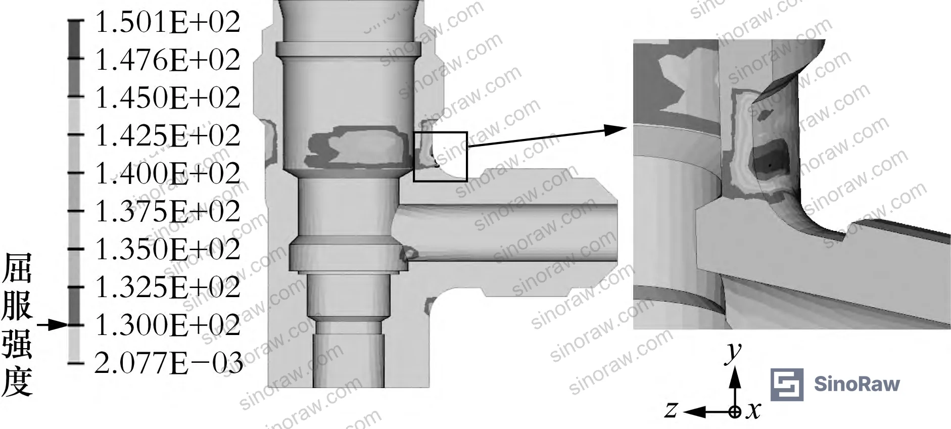
In supplier qualification, we’ve seen cases where manufacturers claim FEA-validated designs but cannot produce the mesh parameters, material input curves, or test correlation data when challenged. A validated model with documented node count (37,359 nodes, 141,617 elements in this study), mesh refinement at radii (minimum 5 element layers through wall thickness), and physical test correlation data is a very different thing from a supplier saying “we use simulation in our development process.” Push for the evidence.
Most procurement teams don’t realize that simulation-test correlation requirements for valve structural integrity are not mandated by JB/T 10648—2017 itself — the standard specifies torque ranges and pressure test requirements, but not how a manufacturer must demonstrate that their wall thickness design is adequate for those torques. That gap is where undersized valves slip through.
Structural Failure Modes and Deformation at Elevated Torque #
When tightening torque exceeds 28.8 N·m, the valve enters plastic deformation territory. The simulation tracked this progression all the way to tensile failure.
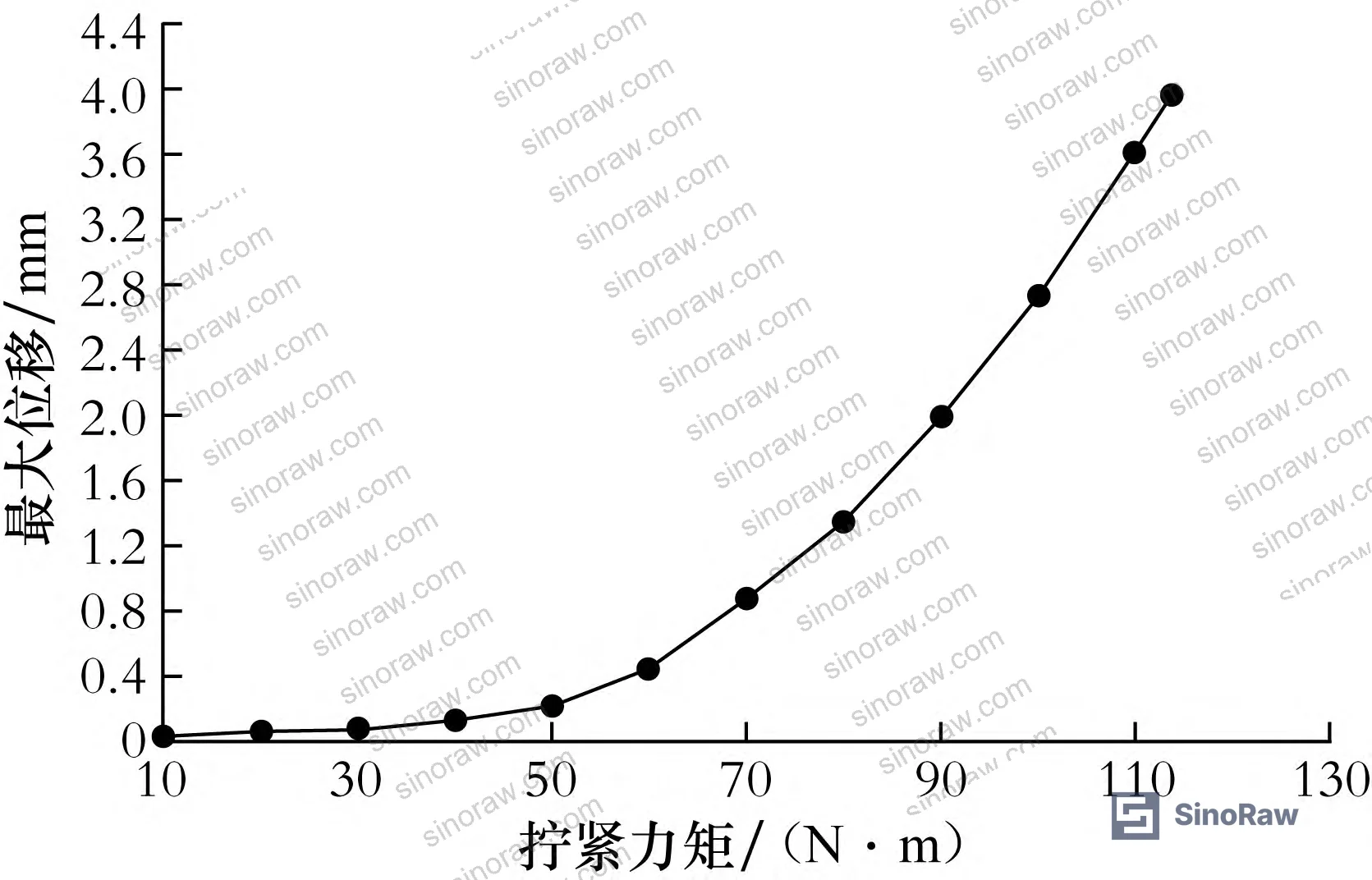
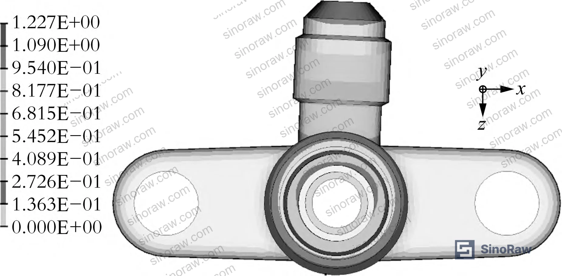
At 113.7 N·m — the torque corresponding to tensile strength (557.3 MPa) at the minimum wall location — maximum connector displacement reaches 3.974 mm, with visible angular offset of the connector relative to the valve body. This is a complete structural failure condition: the connector has permanently rotated and the valve body wall has fractured through.
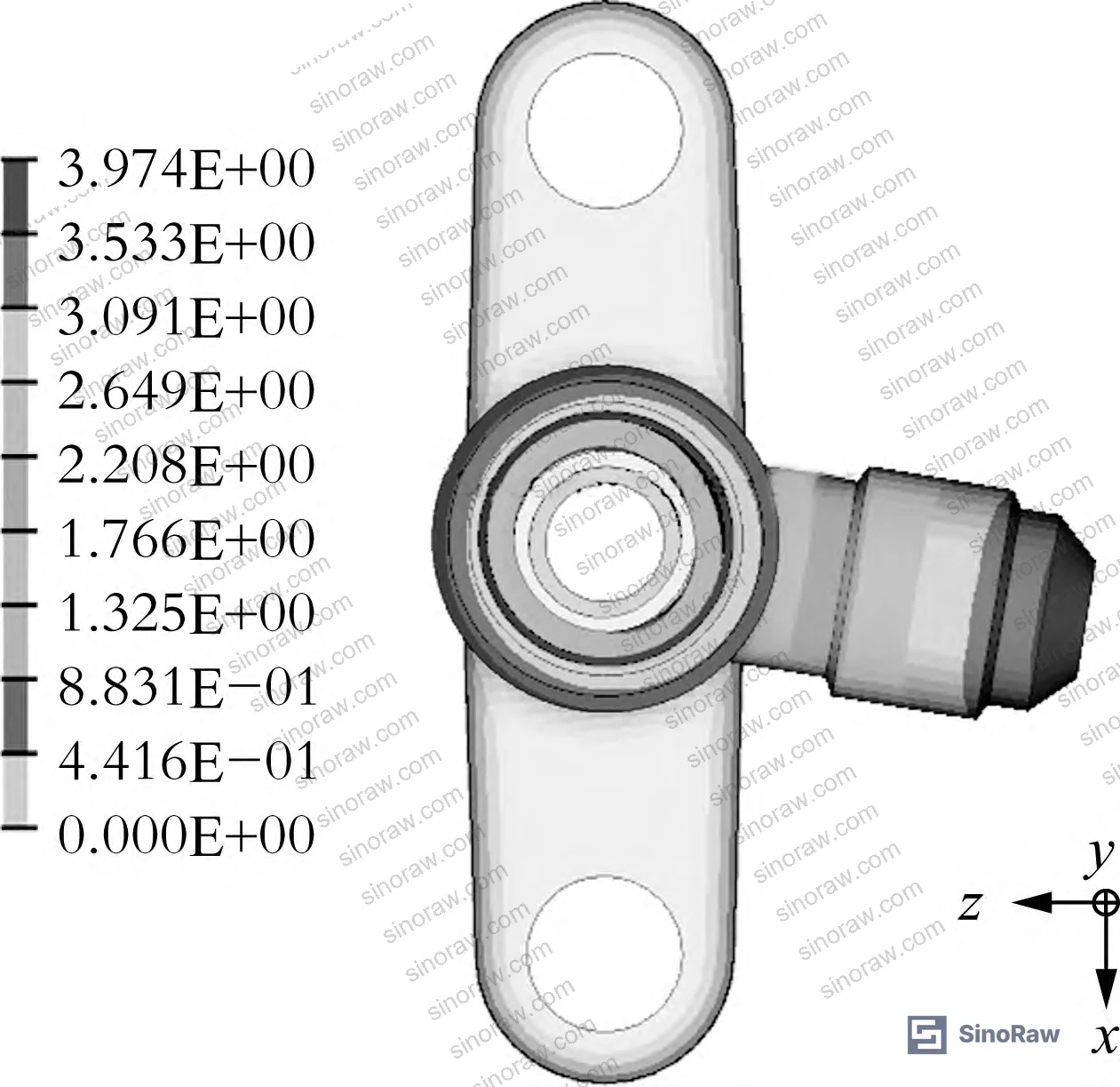
The practical implication here is less about the 113.7 N·m threshold — no competent installer reaches that — and more about what happens between 28.8 N·m and 113.7 N·m. Once the valve has been over-torqued past yield, it’s permanently deformed. The refrigerant circuit may still appear sealed initially, but the wall thickness at the stress concentration zone is now thinner than designed, and fatigue life under thermal cycling is compromised. Valves returned from field for “unexplained leakage” after one or two seasons are often valves that were over-torqued at installation and showing the downstream effects.
Verifying this type of compliance against ISO 5208:2015 Industrial valves — Pressure testing of metallic valves addresses the pressure-holding performance but not the structural margin above installation torque. Both are necessary.
Practical Guidance for Buyers #
When you’re sourcing copper globe valves for HVAC refrigerant service, the minimum wall thickness at the cap nut end is the single most important geometric tolerance to lock down in your drawing specification — more important than nominal bore tolerance, more important than thread class. A valve that passes pressure testing at room temperature can still fail structurally during installation if the wall is 0.1–0.2 mm undersize and the installer applies normal effort.
The JB/T 10648—2017 torque requirement of 20–25 N·m (for 4 mm nominal bore) sounds conservative until you realize the yield-limit torque for a compliant 1.5 mm wall design is only 28.8 N·m. That’s a margin of 3.8 N·m above the upper standard limit. Shrink the wall to 1.3 mm and that margin likely disappears entirely.
For incoming inspection, combine dimensional checking (micrometer or CMM measurement of cap end wall thickness) with a torque verification on a sample basis. Require suppliers to provide the FEA correlation data — not just a certificate. Suppliers using ISO 9001:2015 Quality management systems should have documented design verification records that include simulation validation against physical test. If they can’t produce that for this specific geometry, treat it as a red flag.
Also check material certification. C3771 leaded brass has a defined tensile strength of 557.3 MPa and yield of 130 MPa. Substitution with a lower-grade brass alloy shifts both thresholds downward — the yield-limit torque drops below the standard requirement and you have a non-compliant product that looks identical on a dimension check.
As a Guangzhou-based B2B sourcing service connecting global procurement teams with verified Chinese manufacturers, sinoraw.com works specifically with buyers who need pre-qualified suppliers — not just a list of factories. We evaluate suppliers against technical criteria exactly like these before any RFQ is issued.
For refrigerant valve buyers, compliance with REACH Regulation (EC) No 1907/2006 is an additional consideration given the lead content in C3771 — ensure your supplier holds current substance declarations for the leaded brass composition used.
Need help identifying qualified suppliers for copper globe valves for HVAC refrigerant service? Talk to our sourcing team →
Supplier Qualification Questions #
- What is the minimum wall thickness at the cap nut end of your globe valve body, and can you provide dimensional inspection records showing that this dimension is held to ±0.05 mm or better across production batches?
- At what cap nut tightening torque does the minimum wall thickness location in your design reach the yield strength of the valve body material — and do you have FEA simulation data with physical test correlation (deviation ≤5%) to support that figure?
- What is the documented Young’s modulus, yield strength, and tensile strength of the brass alloy you use for the valve body — and can you provide material test certificates confirming yield strength ≥130 MPa and tensile strength ≥557 MPa for C3771 or equivalent alloy?
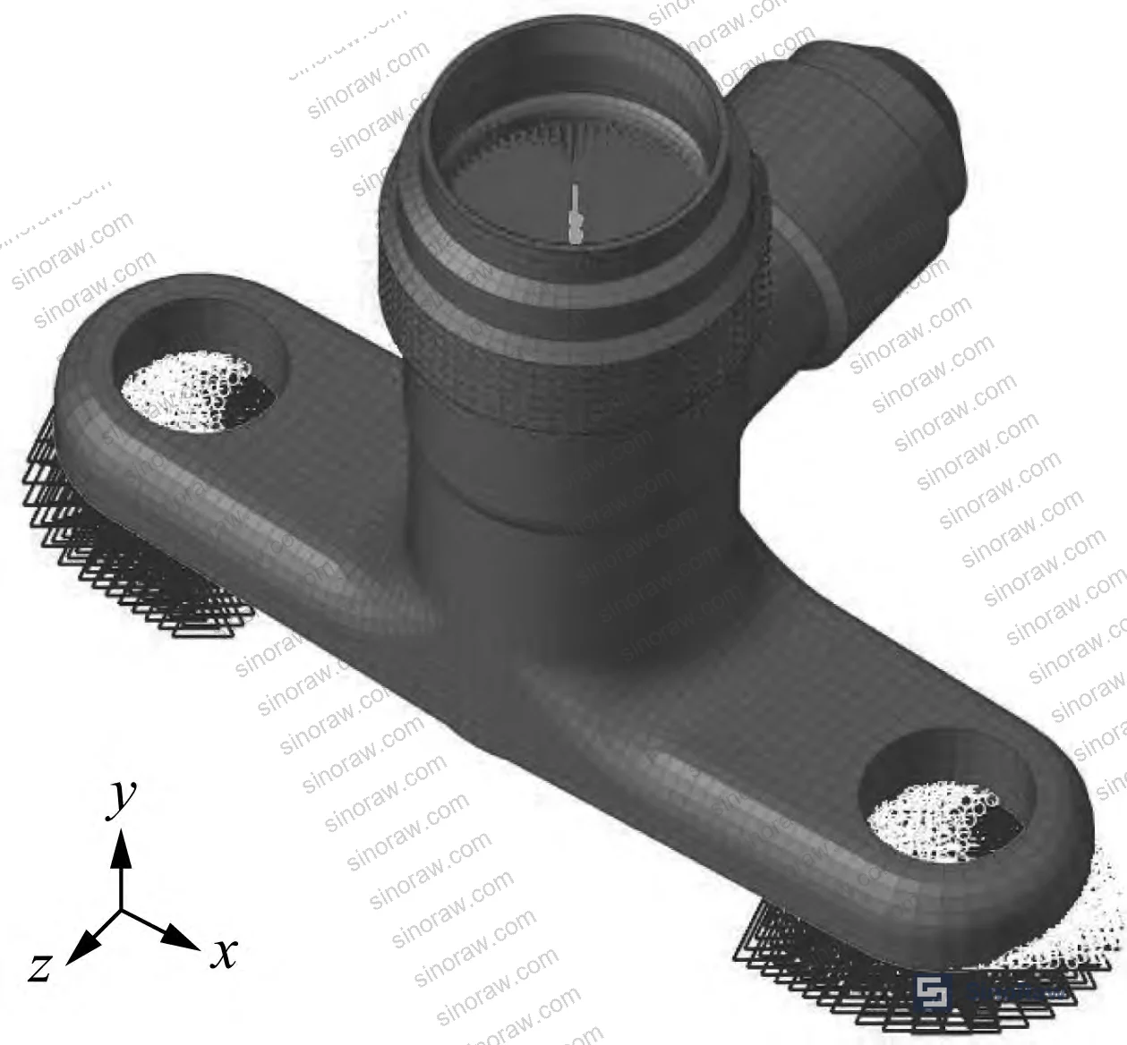
- Does your design verification process for JB/T 10648—2017 compliance include FEA analysis of the torque-stress relationship at the minimum wall thickness, and can you provide the mesh parameters (node count, element count, and element size at radii) used in that analysis?
- At what tightening torque does your valve body reach tensile failure, and what is the maximum connector displacement at that condition — does this exceed 3.974 mm (the validated failure displacement for a 1.5 mm wall design), and if so, what wall thickness change accounts for the difference?
Sourcing Checklist #
- ☐ Minimum wall thickness at cap nut end confirmed at ≥1.5 mm via CMM or micrometer measurement on production samples (not drawing nominal alone)
- ☐ Supplier provides FEA simulation data showing yield-limit tightening torque ≥28.8 N·m for the specified wall thickness, with simulation-to-physical-test deviation ≤5%
- ☐ Material certification confirms valve body alloy yield strength ≥130 MPa and tensile strength ≥557 MPa (C3771 or equivalent leaded brass)
- ☐ Cap nut tightening torque per JB/T 10648—2017 verified at 20–25 N·m for 4 mm nominal bore class, with documented torque tool calibration records
- ☐ FEA mesh documentation available showing minimum 5 element layers through wall thickness at radius transitions and basic element size ≤0.7 mm (0.5 mm at fillets)
- ☐ REACH substance declaration available for leaded brass composition (lead content disclosure per EC No 1907/2006)
- ☐ Incoming inspection protocol includes angular deflection verification or equivalent torque-deformation test on a sampling basis per ISO 2859-1:1999 Sampling procedures for inspection by attributes
Key Specifications Table #
| Parameter | Recommended Value | Verification Method |
|---|---|---|
| Minimum wall thickness (cap nut end) | ≥1.5 mm | CMM dimensional measurement or micrometer on production samples |
| Yield-limit tightening torque | ≥28.8 N·m (must exceed JB/T 10648—2017 upper limit of 25 N·m) | FEA simulation validated by physical deflection test, deviation ≤5% |
| Material yield strength (C3771 leaded brass) | ≥130 MPa | Material test certificate; tensile test per relevant brass alloy standard |
| Material tensile strength (C3771 leaded brass) | ≥557.3 MPa | Material test certificate; confirms failure torque threshold ≥113.7 N·m |
| Cap nut tightening torque (4 mm nominal bore, per JB/T 10648—2017) | 20–25 N·m | Calibrated torque wrench; minimum graduation ≤2 N·m |
| FEA-to-test deviation (angular deflection method) | ≤5% | Optical projector measurement (resolution ≤0.01 μm) vs. FEA predicted deflection angle |
| Maximum connector displacement at tensile failure | ≤3.974 mm | FEA displacement contour output at tensile strength load step |
Can’t find a supplier meeting these specs? Submit your requirements and we’ll match you within 48 hours.
References #
Data source: Torsional Strength Analysis and Experimental Validation of Copper Globe Valves for Refrigerant Service in Air Conditioning Systems, X.-S. Hou et al., International Journal of Refrigeration, 2025
Frequently Asked Questions #
What is the maximum safe tightening torque for a copper globe valve with 1.5 mm minimum wall thickness?
Based on FEA simulation validated against physical testing, the maximum tightening torque before the minimum wall thickness reaches the yield strength of C3771 leaded brass (130 MPa) is 28.8 N·m. The JB/T 10648—2017 standard specifies 20–25 N·m for the 4 mm nominal bore class, giving a margin of 3.8 N·m above the upper standard limit. Exceeding 28.8 N·m causes permanent plastic deformation at the cap end wall.
At what torque does a copper globe valve body fail completely?
At a cap nut tightening torque of 113.7 N·m, the equivalent stress at the minimum wall thickness location reaches the tensile strength of C3771 leaded brass (557.3 MPa), resulting in complete structural failure with a maximum connector displacement of 3.974 mm. This is far above normal installation torque, but relevant when valves are subjected to impact tools without torque limiting.
Why does the stress-torque relationship follow a nonlinear curve rather than a straight line?
Once the material at the minimum wall location begins to yield (around 22–28 N·m), the load redistribution within the wall section changes the stiffness of the system. The effective cross-section resisting the torque is no longer fully elastic, so each additional increment of torque produces a progressively different stress response. This is why linear extrapolation from a single test point is unreliable for predicting failure torque.
How accurate is FEA simulation for this type of valve structural analysis?
The four-sample physical validation in this study showed simulation-to-test deviations ranging from 0.30% to 2.80% — all within the ±5% engineering acceptance band. The key to achieving this accuracy is proper mesh refinement (minimum 5 element layers through wall thickness at radius transitions, 0.5 mm element size at fillets) and using experimentally measured nonlinear stress-strain data for the material model rather than simplified linear elastic properties.
Does wall thickness affect compliance with refrigerant valve pressure testing requirements?
Pressure testing per standards like ISO 5208:2015 evaluates leak integrity under internal pressure — it does not assess structural margin against installation torque. A valve can pass pressure testing and still be undersized in wall thickness at the cap end. The two qualification criteria are complementary, not interchangeable, and both should appear in your supplier qualification requirements. For components in refrigerant circuits, also consider reviewing Fluid Control and Sealing & Thermal category guidance for compatible sealing and connection specifications.
Published by sinoraw.com Technical Team | Request a sourcing quote


