

TL;DR #
Field verification across five major hydraulic control stations confirmed that ceramic ESD raised access flooring achieved a system resistance-to-ground of 7.17×10⁷ Ω — fully compliant with the static-dissipative classification range of 1.0×10⁶ to 1.0×10⁹ Ω under GB/T 36340-2018. For procurement engineers specifying flooring in control rooms housing PLC cabinets, SCADA workstations, or network equipment, this distinction between static-dissipative and conductive grades is not cosmetic — it determines whether your ESD protection system is actually functional. Before issuing any RFQ, confirm load class against your heaviest point-load scenario and verify the resistance classification in writing.
Overview #
If you’re sourcing flooring for an industrial control room, the first thing to understand is that not all “anti-static” flooring is the same — and misspecifying the resistance range is the single most common procurement error I see at this tier. The data supporting this guide comes from a multi-site engineering qualification program conducted across five hydraulic sluice gate control stations, covering a combined installed area exceeding 3,350 m² of ceramic ESD raised access flooring. Compliance verification was performed against GB/T 36340-2018, the current Chinese national standard for anti-static access flooring, using third-party testing of resistance, dimensional tolerance, deflection, and load-bearing capacity. The results provide a rare real-world dataset — not laboratory theory — and they reveal both where this product category performs consistently and where installation quality control can break down.
The control rooms in this deployment housed centralized control consoles, operator workstations, local PLC control cabinets, gate position and load display instruments, video surveillance systems, and network switching equipment. Every one of these device classes is ESD-sensitive. The flooring was the primary static management layer in environments that combine high humidity (riverside locations), continuous human traffic, and dense sensitive electronics — exactly the conditions where polymer-based anti-static coatings have historically failed within 18–36 months.
For buyers evaluating Industrial Electrical infrastructure components, the ceramic ESD raised floor category sits at the intersection of structural engineering and EMC compliance. It is worth understanding it in that dual frame.
Ceramic ESD Raised Floor Construction and ESD Dissipation Mechanism #
The product architecture here is specific and matters for procurement. The floor tile itself is a full-steel-shell panel with internal cement fill. The face layer is white polycrystalline ceramic — fired with integrated nano anti-static additives, not coated post-production. This is an important distinction: nano-additive integration during firing produces stable, homogeneous resistivity throughout the tile body rather than a surface layer that degrades with abrasion or cleaning chemicals.
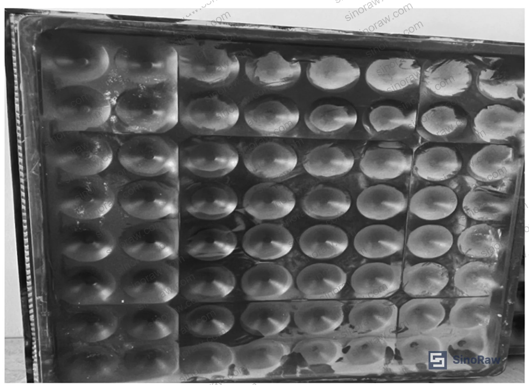
The perimeter of each tile is sealed with black conductive PVC edge strips. The back face is formed with convex hemispherical protrusions — this geometric detail increases steel plate contact area, improves panel stability under eccentric loading, and reduces creep deformation over the service life. Panels sit on adjustable steel pedestals connected by crossbeams, with rubber buffer pads at contact points. The grounding path runs: tile surface → conductive edge strip → metal pedestal frame → grounding flat iron → earth.
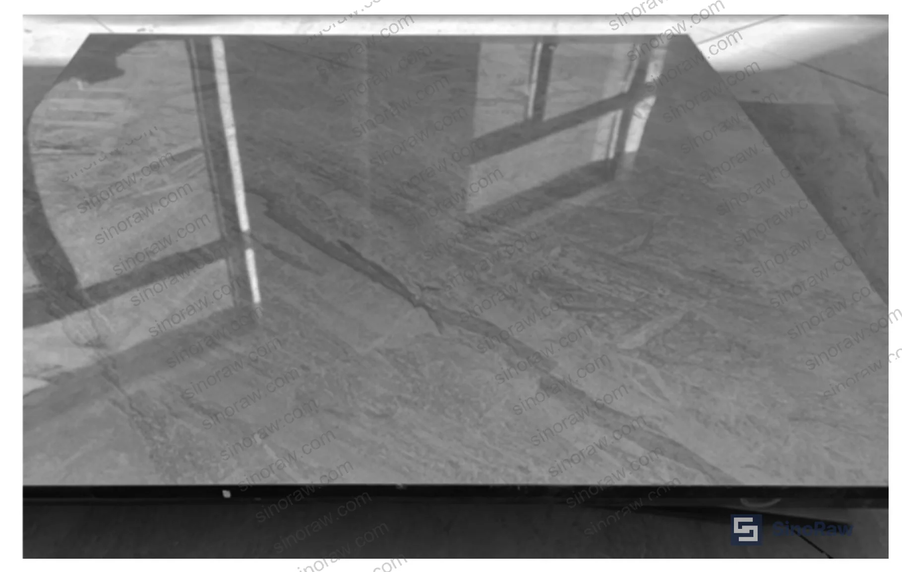
The support configuration in the Weihe River main channel project used perimeter-support framing rather than four-point support. Perimeter support distributes load more evenly across the panel edges and is the preferred configuration for rooms with heavy rolling equipment or dense cable tray installations beneath the floor void.
The under-floor cavity serves dual functions: cable routing for signal lines, power cables, and grounding conductors, and maintenance access. In sluice control rooms specifically, this eliminates surface cable runs that interfere with operator movement and panel door access.
Measured resistance-to-ground from incoming material inspection came in at 7.17×10⁷ Ω. Under GB/T 36340-2018, the static-dissipative classification requires values between 1.0×10⁶ Ω and 1.0×10⁹ Ω. The conductive classification requires 1.0×10⁴ Ω to 1.0×10⁶ Ω. This specific product falls cleanly within the static-dissipative band — not conductive. Most buyers sourcing for PLC and SCADA environments actually want static-dissipative, not conductive, because the conductive range can create ground-loop issues in sensitive signal circuits. Honestly, most procurement teams don’t realize this distinction exists until they’ve already specified the wrong grade.
Compliance with ISO 9001:2015 Quality management systems should be a baseline supplier requirement — but for this product category, GB/T 36340-2018 material certification is the document that actually tells you what you bought.
Load Classification, Dimensional Tolerance, and Structural Verification #
This is where the procurement decision gets technical and where cutting corners on specification has real consequences. GB/T 36340-2018 defines six load classification tiers — CQ, Q, P, B, Z, and CZ — with progressively higher concentrated load, uniform distributed load, and ultimate concentrated load values.
Load classification comparison across GB/T 36340-2018 tiers:
| Load Class | Concentrated Load (N) | Uniform Load (N) | Ultimate Concentrated Load (N) |
|---|---|---|---|
| CQ | 1,960 | 9,720 | 5,880 |
| Q | 2,950 | 12,500 | 8,850 |
| P | 3,560 | 16,000 | 10,680 |
| B | 4,450 | 23,000 | 13,350 |
| Z | 5,560 | 33,000 | 16,680 |
| CZ | 6,675 | 43,000 | 20,025 |
The verification testing for this project confirmed deflection at center point of 0.78 mm and at edge midpoint of 0.98 mm, both well within the ≤2 mm deflection limit. Residual deformation at center point was 0.10 mm (edge midpoint: 0.13 mm, diagonal quarter-point: 0.08 mm), against a ≤0.25 mm limit. The ultimate concentrated load tests returned values of 6,890 N at center, 5,960 N at edge midpoint, and 6,110 N at the diagonal quarter-point.
Dimensional tolerances from incoming inspection: panel dimension tolerance was +0.20 mm against a 0~+0.40 mm specification; thickness tolerance was +0.30 mm; surface planarity was 0.50 mm against ≤0.60 mm; adjacent edge perpendicularity was 0.21 mm against ≤0.30 mm. Every measured value passed.
Honestly, most buyers over-specify load class for standard control room applications. A B-class or P-class panel is sufficient for operator foot traffic and typical PLC cabinet wheel loads. You only need Z or CZ if you’re moving transformer units or heavy switchgear across the floor regularly. Over-specifying pushes installed cost up 25–40% with no functional benefit in a normal instrument room environment.
For buyers also evaluating complementary under-floor infrastructure, the Cables & Connectivity category covers cable management solutions that integrate with raised floor systems.
Installation Process, Quality Control Failures, and Acceptance Protocol #
The installation sequence is strictly ordered: site preparation → floor surface cleaning → concealed works acceptance → layout and positioning → pedestal and crossbeam assembly → concealed structural inspection → floor panel installation → height adjustment → final acceptance. Deviation from this sequence — specifically skipping the concealed works inspection before panel installation — was identified as the primary failure mechanism in under-performing installations.
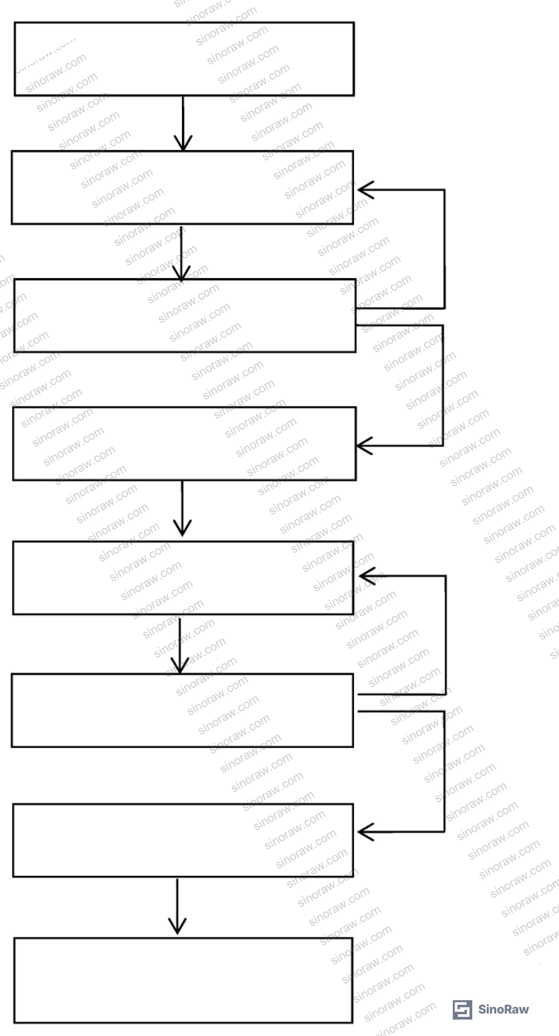
In supplier qualification for this program, a PDCA + 5M1E quality management framework was applied with mandatory incoming material inspection. Panels were tested on arrival before installation — resistance, dimensional tolerances, and load-bearing were all verified by third-party laboratory. This is where the friction became visible: incoming batches that failed first inspection triggered doubled sample size re-testing. If the second round failed, the entire batch was rejected and removed from site. This is the correct protocol, and it caught non-conformances that visual inspection alone would have missed.
The installation method requires a retrograde (backwards-walking) technique — the installer lays panels working away from already-installed sections using a suction cup lifter to prevent foot contact with completed areas. Positioning uses laser levels, not chalk lines, specifically to avoid surface contamination that would affect the final resistance measurements.
Acceptance testing for this product category is unusual: it requires participation from the testing laboratory in addition to the standard construction unit, contractor, and supervision unit. Most water conservancy and infrastructure projects don’t require independent lab involvement at the acceptance stage — this is a meaningful departure from standard practice and a sign that ESD performance verification cannot be delegated to visual inspection alone.
Industry observation: current procurement teams at many infrastructure projects are still specifying polymer anti-static coatings (epoxy, PVC sheet, rubber mat) for control room floors — partly because these alternatives appear cheaper at the unit price level. What that calculation misses is the recoating or replacement cycle, which in riverside and high-humidity environments typically runs every 2–4 years. The ceramic ESD floor’s service life advantage eliminates multiple replacement cycles and their associated downtime costs. The REACH Regulation (EC) No 1907/2006 compliance documentation is also straightforward for ceramic products versus solvent-containing polymer coatings, which matters for projects with EU export or funding dimensions.
The five installations in this project covered: Yantuzhuang sluice gate control room (1,180 m²), Xiaohekou sluice (723 m²), Changhongqu flood return sluice (630 m²), Changhongqu flood diversion sluice (390 m²), and Baisipo flood diversion sluice (435 m²). Sluice gate dimensions ranged from 7.0 m × 4.3 m to 11.0 m × 5.5 m (width × height), with hoist capacities from 2×160 kN to 2×400 kN. The flooring has been in continuous service and the operating management teams have confirmed effective static dissipation across all sites.
Practical Guidance for Buyers #
When you’re specifying ceramic ESD raised access flooring for a control room project, the three decisions that matter most are resistance classification, load class, and the grounding continuity design. Get the resistance classification wrong and your ESD protection doesn’t function. Under-specify the load class and you’ll see panel deflection under cabinet loading. Neglect the grounding conductor design and the entire system — however well-specified the panels are — fails to dissipate charge.
For control rooms housing PLC cabinets, SCADA workstations, or network switching equipment, static-dissipative grade (1.0×10⁶ to 1.0×10⁹ Ω) is the correct specification in most cases. Conductive grade (1.0×10⁴ to 1.0×10⁶ Ω) is appropriate for semiconductor cleanroom environments where the standards are more demanding. Don’t let a supplier upsell you to conductive grade for a standard instrument room.
Verify that the supplier’s panels comply with GB/T 36340-2018 with third-party test reports covering all three of: resistance-to-ground, dimensional tolerances, and all three load-bearing tests. Certificates alone without test data are not sufficient documentation.
At sinoraw.com, our team works directly with procurement engineers and sourcing managers to identify and pre-qualify Chinese manufacturers in this category — so you’re issuing RFQs to suppliers who can actually deliver compliant product, not just quoting on it. The RoHS Directive 2011/65/EU compliance of conductive components (edge strips, pedestal coatings) is a checkpoint we routinely include in our supplier evaluations for buyers with EU-destined projects.
Need help identifying qualified suppliers for ceramic ESD raised access flooring? Talk to our sourcing team →
Supplier Qualification Questions #
- What is the measured resistance-to-ground for your panels under GB/T 36340-2018, and can you provide third-party test certificates confirming the value falls within the static-dissipative range of 1.0×10⁶ to 1.0×10⁹ Ω?
- What load classification does your product meet, and can you provide deflection test data showing center-point deflection ≤2 mm and residual deformation ≤0.25 mm under the applicable concentrated and uniform load values?
- Is the anti-static property integrated into the ceramic tile during the firing process via nano anti-static additives, or is it achieved through surface coating — and how does your batch release specification verify that bulk resistivity is homogeneous throughout the tile body?
- What are the dimensional tolerances your panels are manufactured to, specifically panel width tolerance (target 0~+0.4 mm), surface planarity (≤0.6 mm), and adjacent edge perpendicularity (≤0.3 mm), and what inspection method do you use to verify these at outgoing QC?
- Does your installation system include conductive PVC edge strips and a documented grounding continuity path from tile surface through metal pedestals to earth, and can you provide grounding resistance values for the assembled system as installed?
Sourcing Checklist #
- ☐ Supplier provides GB/T 36340-2018 third-party test certificate with measured resistance-to-ground value documented (static-dissipative: 1.0×10⁶–1.0×10⁹ Ω; conductive: 1.0×10⁴–1.0×10⁶ Ω)
- ☐ Load classification confirmed in writing with deflection test data: center-point deflection ≤2 mm, residual deformation ≤0.25 mm under specified concentrated load
- ☐ Panel dimensional tolerance test report confirms surface planarity ≤0.6 mm and adjacent edge perpendicularity ≤0.3 mm
- ☐ Anti-static nano additive integration is confirmed as bulk-fired (not surface-coated) — supplier can provide cross-section resistivity data or equivalent documentation
- ☐ Supplier can provide REACH compliance documentation for conductive edge strip materials and pedestal coating
- ☐ Installation specification includes laser-level positioning procedure and retrograde installation method to prevent contamination of installed panels
- ☐ Grounding system design includes flat iron earth connection with documented grounding path resistance ≤10 Ω for the assembled system
- ☐ Incoming material inspection protocol requires third-party laboratory testing before installation, with doubled sample inspection triggered by any first-round non-conformance
Key Specifications Table #
| Parameter | Recommended Value | Verification Method |
|---|---|---|
| Resistance-to-ground (static-dissipative) | 1.0×10⁶ to 1.0×10⁹ Ω | Third-party resistance measurement per GB/T 36340-2018; project result: 7.17×10⁷ Ω |
| Center-point deflection under concentrated load | ≤2 mm | Load deflection test per GB/T 36340-2018; project result: 0.78 mm |
| Residual deformation after concentrated load | ≤0.25 mm | Residual deformation measurement per GB/T 36340-2018; project result: 0.10 mm |
| Surface planarity | ≤0.6 mm | Dimensional inspection with straightedge and feeler gauge; project result: 0.50 mm |
| Adjacent edge perpendicularity | ≤0.3 mm | Square and feeler gauge measurement; project result: 0.21 mm |
| Panel width/length tolerance | 0 to +0.4 mm | Dimensional inspection; project result: +0.20 mm |
| Ultimate concentrated load at center | ≥5,880 N (CQ minimum) to ≥20,025 N (CZ) | Destructive load test per load class; project center result: 6,890 N |
Can’t find a supplier meeting these specs? Submit your requirements and we’ll match you within 48 hours.
References #
Data source: Performance Evaluation and Application of Ceramic Anti-Static Raised Access Flooring Systems in Industrial Control Environments, C. Hu et al., Construction and Building Materials, 2024
Frequently Asked Questions #
What is the difference between conductive and static-dissipative ESD flooring, and which should I specify for a PLC control room?
Conductive flooring (1.0×10⁴–1.0×10⁶ Ω) drains charge very rapidly and is primarily used in semiconductor manufacturing cleanrooms. Static-dissipative flooring (1.0×10⁶–1.0×10⁹ Ω) drains charge more gradually, which is actually preferable for instrument rooms housing PLCs, SCADA systems, and network equipment — rapid discharge in a conductive floor can itself create transient currents that interfere with sensitive signal circuits. For standard industrial control rooms, static-dissipative is the correct specification in the vast majority of cases.
Why is ceramic ESD flooring preferred over epoxy or PVC anti-static coatings in humid environments?
Polymer anti-static coatings — epoxy, PVC sheet, rubber mat — degrade in high-humidity environments through moisture absorption, surface oxidation, and contamination, with resistivity values drifting out of specification within 2–4 years in riverside or coastal locations. Ceramic ESD flooring with nano-additive integration maintains stable bulk resistivity throughout its service life because the anti-static property is structural, not surface-dependent.
What load class should I specify for a typical sluice gate or water conservancy control room?
For rooms with standard operator workstations, PLC cabinets on casters, and network rack equipment, P-class (3,560 N concentrated load) or B-class (4,450 N) is typically sufficient. Z or CZ class is warranted only if heavy switchgear or transformer units will be moved across the floor on wheeled dollies.
What should I check during incoming material inspection before installation begins?
Three test categories are non-negotiable: resistance-to-ground (confirm value falls within specified resistance band), dimensional tolerances (planarity ≤0.6 mm, perpendicularity ≤0.3 mm, dimension tolerance 0–+0.4 mm), and load-bearing performance (deflection and residual deformation under class-appropriate loads). Visual inspection alone — checking for chips, color consistency, and edge strip adhesion — is necessary but not sufficient.
Can the under-floor cavity be used for cable routing in ESD-sensitive environments?
Yes, and this is one of the primary functional advantages of the raised floor system. Signal cables, power cables, and grounding conductors can all be routed through the void below the panels, eliminating surface cable runs. The cable routing must be completed and inspected before panel installation, as accessing the void after installation requires panel removal. Rodent prevention measures (sealing penetrations, perimeter closure) are mandatory where the building envelope has rodent exposure risk.
Published by sinoraw.com Technical Team | Request a sourcing quote


