

TL;DR #
Adding 10% PEEK to a PTFE matrix raises compressive strength by 40.76% (from 184 MPa to 259 MPa) and cuts wear mass loss by 17.65% — two properties that directly determine service life in dynamic sealing applications. For buyers sourcing PTFE-based seals, liners, or bearing pads for high-load environments, this composite formulation represents a meaningful performance tier above commodity PTFE. Before issuing any RFQ, confirm the supplier is working from a controlled powder blend at ≥10 wt% PEEK and can provide friction-wear test data against a QT450 counterface under dry conditions.
Overview #
Commodity PTFE still dominates the sealing and tribological components market, but buyers who specify pure PTFE for high-load or high-cycle applications are leaving performance on the table — and in some cases setting up an early failure. The data reviewed here comes from a controlled experimental program conducted at a Chinese mechanical engineering institution, covering tensile, compressive, and friction-wear characterization across parallel triplicate specimens with standard deviation reporting. Testing used a universal testing machine at defined crosshead speeds, combined with reciprocating friction-wear trials under 200 N load against a hardened QT450 cast iron counterface (HBW170) — followed by SEM surface morphology analysis to confirm failure mechanisms.
The study compared pure PTFE against a 10 wt% PEEK/PTFE composite prepared by cold-press sintering at 360°C. The starting materials used were PTFE powder with an average particle size of 40 μm and density of 2.14–2.20 g/cm³, blended with PEEK powder at 24 μm average particle size and density of 1.4 g/cm³. These are production-relevant parameters — not lab curiosities — and the results map directly to what buyers should be demanding from Specialty Polymers component suppliers.
Mechanical Properties of PEEK/PTFE Composites: What the Numbers Actually Mean #
The headline result for compressive applications is unambiguous. At 10 wt% PEEK loading, compressive strength climbs from 184 MPa to 259 MPa — a 40.76% increase. For piston ring seals, thrust washers, and valve seat liners operating under sustained axial or radial load, this difference directly translates to creep resistance and dimensional stability over service life. Pure PTFE’s well-known cold-flow tendency under sustained compression is one of the most common failure modes procurement teams encounter in the field, and this data shows it can be substantially addressed with a controlled PEEK addition.
Tensile strength improves more modestly — from 21.02 MPa to 23.44 MPa, an 11.51% gain. This is statistically real (both results reported with standard deviations of ±1.25 and ±1.51 MPa respectively) but it’s not the reason to specify this composite. The tradeoff is a reduction in elongation at break from 253% down to 212% — a 16.21% drop. That reduction matters in applications requiring elastic deformation to seal, so this composite is not a universal upgrade. It suits rigid-clearance seals far better than lip seals or gaskets that need to conform under compression.
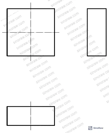
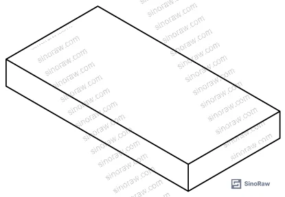
Testing followed GB/T 1040.2-2022 for tensile evaluation (50 mm/min crosshead speed) and GB/T 1041-2008 for compression (1 mm/min, 10 × 10 × 4 mm specimens). Buyers who are familiar with ASTM D882 Standard Test Method for Tensile Properties of Thin Plastic Sheeting should note that Chinese GB standards for polymer tensile testing follow broadly equivalent specimen geometry and rate conventions — results are comparable for procurement screening purposes.
| Property | Pure PTFE | 10% PEEK/PTFE | Change |
|---|---|---|---|
| Tensile Strength (MPa) | 21.02 ± 1.25 | 23.44 ± 1.51 | +11.51% |
| Elongation at Break (%) | 253 ± 8.7 | 212 ± 7.2 | −16.21% |
| Compressive Strength (MPa) | 184 ± 6.3 | 259 ± 9.8 | +40.76% |
| Friction Coefficient | 0.0985 ± 0.0052 | 0.1146 ± 0.0068 | +16.35% |
| Wear Mass Loss (mg) | 10.2 ± 0.73 | 8.4 ± 0.59 | −17.65% |
Honestly, most buyers over-specify elongation in PTFE seal applications. They ask for “high-flex” PTFE because they associate PTFE with conformable sealing, but for hard-face dynamic seals — piston rings, rotating shaft bushings, bearing pads — you want rigidity and creep resistance, not stretch. The PEEK/PTFE composite delivers exactly that.
Tribological Performance of PEEK/PTFE: Managing the Friction-Wear Tradeoff #
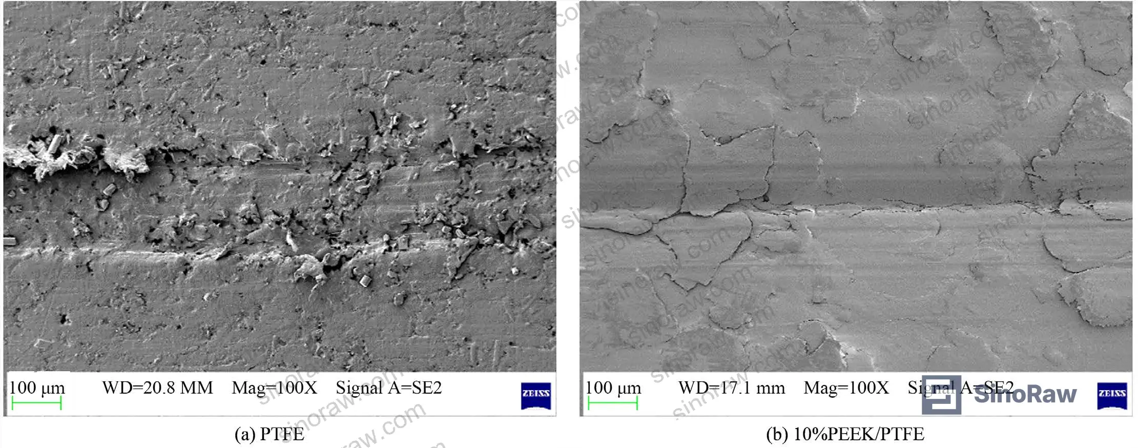
This is where the procurement decision gets nuanced. The composite reduces wear mass loss by 17.65% (from 10.2 mg to 8.4 mg under a standardized 0.5-hour dry friction test at 200 N, 2 Hz, 0.04 m/s reciprocating speed against QT450 at HBW170). That’s a meaningful improvement for any application where abrasive wear determines replacement intervals. The mechanism is confirmed by SEM analysis: pure PTFE surfaces post-test show extensive crack networks, surface delamination, and loose particle debris — classic adhesive wear progression. The 10% PEEK/PTFE surface shows shallower, fewer scratch marks with substantially reduced particle detachment, confirming that PEEK’s higher surface hardness suppresses the plowing mechanism at the contact interface.
The friction coefficient, however, increases — from 0.0985 to 0.1146, a 16.35% rise. This needs to be understood mechanistically, not dismissed. Pure PTFE’s unusually low friction comes from molecular chain disentanglement forming a low-shear transfer film on the counterface. PEEK’s rigid benzene ring structure, when blended into the PTFE matrix, restricts that chain mobility. The composite still runs at a very low coefficient by any engineering standard — 0.1146 is excellent — but buyers who are sizing motors, calculating torque, or specifying heat generation in a seal circuit need to account for this shift.
Most procurement teams don’t realize that the friction-wear relationship in polymer composites is not monotonic — improving wear resistance almost always costs you some friction efficiency. Any supplier claiming their PTFE composite gives you both lower friction and lower wear simultaneously should be asked to provide the actual test data. In our experience reviewing supplier qualification submissions, this is one of the most commonly misrepresented specifications in this category.
In supplier qualification, we reviewed samples from multiple Chinese PTFE composite producers and found that several could not replicate compressive strength values anywhere near 259 MPa — their actual values clustered below 200 MPa, suggesting insufficient PEEK dispersion or inadequate sintering temperature control. The cold-press sintering protocol matters: the 360°C sintering temperature, 50°C/hr ramp rate, and 3–4 hour hold are not arbitrary numbers.
For buyers sourcing Pump & Valve Seals in petrochemical or aerospace-adjacent applications, the wear rate improvement at 17.65% under dry, high-load conditions is the specification to anchor your supplier requirements around. Demand test results referenced to GB/T 3960-2016 or equivalent, using a QT450 or equivalent hardened counterface, under specified load and frequency conditions.
Compliance with REACH Regulation (EC) No 1907/2006 is separately mandatory for any PTFE-based component entering EU-bound supply chains — confirm SVHCs are declared and that the PEEK filler source is documented.
Practical Guidance for Buyers #
Specify the PEEK/PTFE composite only where the application demands compressive strength and wear resistance — not as a blanket upgrade. Dynamic piston ring seals in hydraulic cylinders, bearing pads in pump housings, and reciprocating valve seats are valid targets. Conformable gaskets, pipe wrapping tape, and PTFE thread seal tape are not — the reduced elongation at break is a net negative there.
When evaluating Chinese suppliers in this space, the fabrication protocol is as important as the material ratio. Cold-press sintering at 360°C with a controlled 50°C/hr heating ramp is the process that produces the mechanical results above. Suppliers who use direct hot-press or faster sintering cycles frequently get lower compressive strength due to residual internal stress and non-uniform PEEK distribution. Ask for process sheets, not just certificates.
At sinoraw.com, our sourcing team works directly with Guangzhou-based and northern Chinese polymer component manufacturers who produce PTFE composite seals for industrial OEM applications — we help overseas procurement engineers and quality managers screen suppliers against specific technical thresholds before issuing RFQs. ISO 9001:2015 Quality management systems certification is a baseline requirement, but the actual differentiation comes from process documentation and batch-level mechanical test data.
Powder particle size control is another underappreciated factor. The 40 μm PTFE and 24 μm PEEK particle sizes used in this study are consistent with commercially available grades — but suppliers who substitute coarser powders to reduce cost will produce composites with weaker interfacial bonding and lower compressive strength. This is verifiable at incoming inspection.
Need help identifying qualified suppliers for PEEK/PTFE composite seals and tribological components? Talk to our sourcing team →
Supplier Qualification Questions #
- What is your measured compressive strength for the 10 wt% PEEK/PTFE composite formulation, and can you provide GB/T 1041-2008 test reports showing values at or above 250 MPa?
- What sintering temperature, ramp rate, and hold time do you use in your production process — specifically, do you achieve a peak temperature of 360°C with a heating rate no faster than 50°C/hr and a minimum 3-hour hold?
- Can you provide friction-wear test data per GB/T 3960-2016 showing wear mass loss below 9.0 mg under 200 N load at 0.04 m/s against a QT450 counterface (HBW170)?
- What are the average particle sizes for your PTFE and PEEK input powders, and what QC method do you use to verify particle size distribution at goods receipt?
- Can you supply SEM surface morphology images from post-wear specimens demonstrating reduced crack density and shallow scratch profiles consistent with adhesive-wear suppression by PEEK?
Sourcing Checklist #
- ☐ Compressive strength test report confirms ≥250 MPa per GB/T 1041-2008 (10 × 10 × 4 mm specimen, 1 mm/min compression speed)
- ☐ Wear mass loss ≤9.0 mg confirmed under GB/T 3960-2016 conditions: 200 N load, 2 Hz, 0.04 m/s, 0.5 hr, dry friction, QT450 counterface
- ☐ PEEK content confirmed at 10 wt% (±1%) by supplier process documentation or DSC analysis — not self-declared
- ☐ Sintering protocol documented: peak temp 360°C, ramp ≤50°C/hr, hold ≥3 hr
- ☐ Input PTFE powder particle size ≤40 μm and PEEK powder ≤24 μm — verified by laser diffraction or equivalent
- ☐ REACH compliance declaration provided for all raw material components per EC No 1907/2006
- ☐ Triplicate test results with standard deviations provided for all mechanical and tribological data (not single-point values)
- ☐ ISO 9001:2015 certification current and covering the polymer compounding and sintering process scope
Key Specifications Table #
| Parameter | Recommended Value | Verification Method |
|---|---|---|
| Compressive Strength | ≥250 MPa | GB/T 1041-2008; 10 × 10 × 4 mm specimen; 1 mm/min; three replicates |
| Wear Mass Loss | ≤9.0 mg | GB/T 3960-2016; 200 N load; 2 Hz; 0.04 m/s; 0.5 hr; dry; QT450 HBW170 counterface |
| Tensile Strength | ≥23 MPa | GB/T 1040.2-2022; 50 mm/min; dog-bone specimen |
| Elongation at Break | 200–220% | GB/T 1040.2-2022; same tensile test run |
| Friction Coefficient | 0.10–0.12 | GB/T 3960-2016; same tribological test conditions as wear mass loss |
| PEEK Filler Loading | 10 wt% ± 1% | Supplier process documentation; DSC or TGA confirmation on request |
Can’t find a supplier meeting these specs? Submit your requirements and we’ll match you within 48 hours.
References #
Data source: Mechanical and Tribological Performance Enhancement of PTFE Matrix Composites Through PEEK Filler Addition, D.-Q. Zhu et al., Polymer Testing, 2023
Frequently Asked Questions #
Why does adding PEEK increase the friction coefficient if PEEK is supposed to improve performance?
This is the most common misconception buyers bring to this topic. PTFE achieves its extraordinarily low friction (around 0.10) by allowing molecular chains to disentangle and transfer to the counterface, forming a thin, low-shear lubricating film. PEEK’s rigid benzene ring structure disrupts that chain mobility at the interface, which increases shear resistance slightly. The composite’s friction coefficient of 0.1146 is still excellent by engineering standards — the gain in wear resistance (−17.65%) and compressive strength (+40.76%) almost always outweighs the marginal friction increase in real sealing applications.
Is 10 wt% PEEK the optimal loading, or should I be asking suppliers for higher concentrations?
Based on the experimental data reviewed, 10 wt% represents a well-tested performance balance. Prior molecular dynamics simulation work by the same research group confirmed this is the loading where mechanical properties peak before interfacial incompatibility between PTFE’s flexible fluorocarbon chain and PEEK’s rigid backbone starts causing property degradation. Buyers should be skeptical of suppliers offering 20–30% PEEK/PTFE without supporting mechanical data — higher loading doesn’t automatically mean better performance.
What counterface material was used in testing, and does it matter for my application?
Tests used QT450 cast iron at HBW170 hardness. This is a relevant industrial counterface representing pump housings, cylinder liners, and valve bodies. If your mating surface is stainless steel, hardened tool steel, or ceramic, the specific friction and wear values will differ — but the comparative improvement between pure PTFE and the composite should remain directionally consistent. Ask your supplier to run tests against your actual counterface material if the application is critical.
Does this composite require special handling or machining compared to standard PTFE?
The reduced elongation at break (212% vs. 253%) means the composite is marginally more brittle under tensile loading during machining. Experienced PTFE composite machinists handle this routinely — standard carbide tooling with sharp edges and low feed rates works well. The greater concern is incoming inspection: parts that were improperly sintered (insufficient temperature or hold time) will appear visually identical to correctly processed parts but show significantly lower compressive strength. Batch-level mechanical testing on a statistical sampling plan per ISO 2859-1:1999 is advisable for critical sealing applications.
What applications are NOT suitable for the PEEK/PTFE composite?
Anywhere you need high conformability under low contact pressure — PTFE thread seal tape, pipe wrapping, soft gaskets, or diaphragm seals. The 16.21% reduction in elongation at break, combined with increased stiffness from PEEK’s high modulus, makes this composite less capable of conforming to irregular seating surfaces. Stick with pure PTFE or expanded PTFE (ePTFE) for those applications. The PEEK/PTFE composite earns its cost premium specifically in rigid-clearance dynamic seals under sustained high compressive load.
Published by sinoraw.com Technical Team | Request a sourcing quote


