

TL;DR #
At an interference fit of δ = 0.1 mm, V-shaped NBR seal rings in high-pressure fracturing pump plungers achieve contact pressures that reliably exceed medium pressure across both suction and discharge strokes — below this threshold, the main sealing surface loses positive contact during suction, guaranteeing eventual leakage. Buyers specifying plunger seal assemblies for fracturing service at 60–140 MPa must treat interference fit tolerance as a primary procurement parameter, not a manufacturing footnote. Request FEA-validated interference fit data at rated pressure before issuing any RFQ.
Overview #
If your procurement team is still selecting fracturing pump plunger seals based on hardness specs and material grade alone, you are buying the wrong thing for the wrong reasons. The interference fit value — that single geometric parameter controlling how tightly the V-ring stack is compressed against the plunger — is the dominant variable governing whether your seal survives 95 strokes per minute at 140 MPa or fails within the first few operating hours.
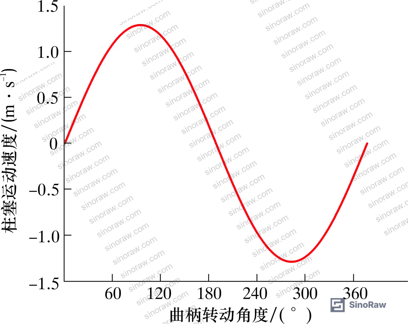
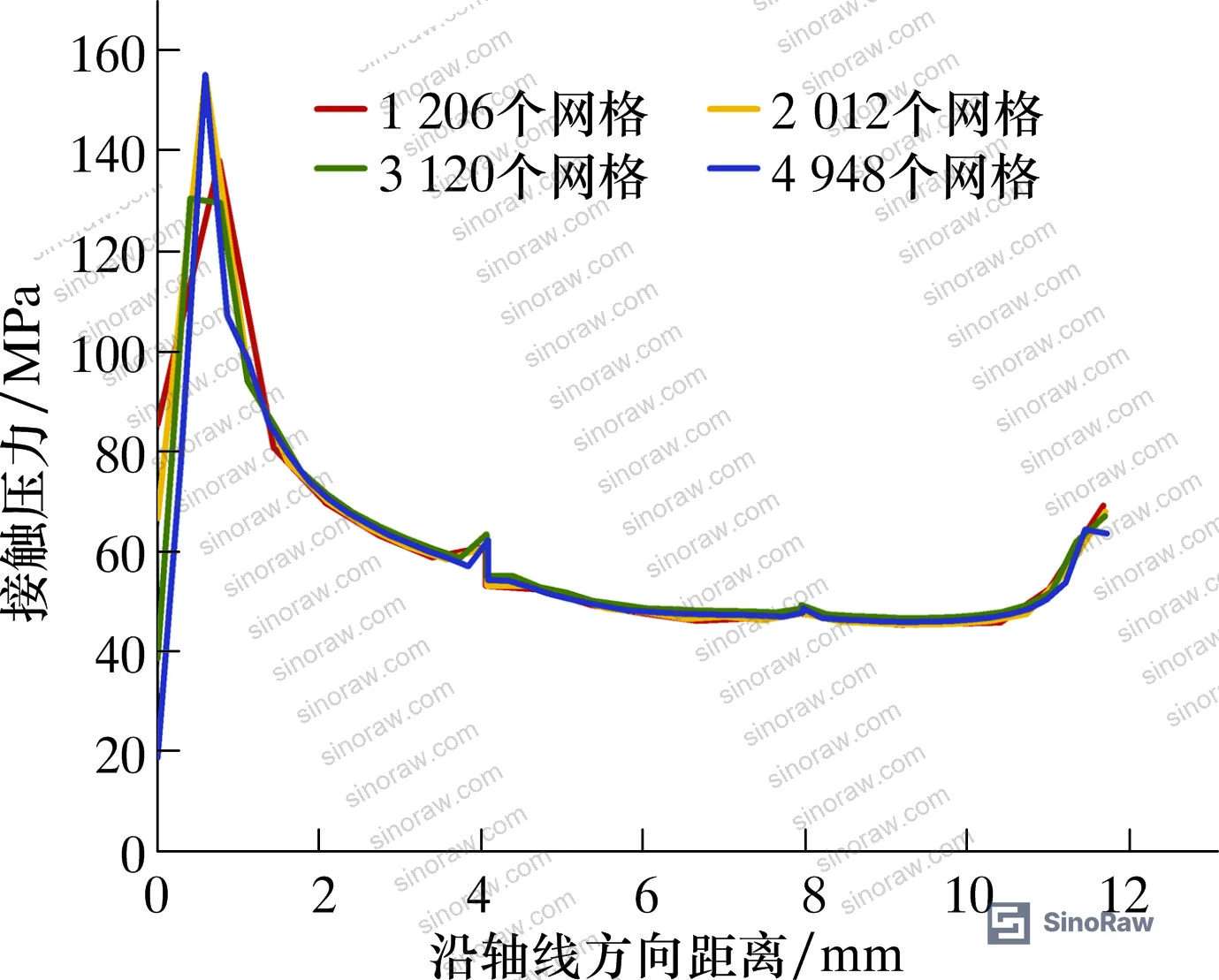
Recent finite element simulation studies conducted at a petroleum engineering research institution modeled a 7000-type fracturing pump plunger seal assembly using a 2D axisymmetric FEA framework, applying sinusoidal velocity motion to replicate real crankshaft-driven plunger kinematics. The model covered a plunger diameter of 127 mm with V-ring geometry (inner diameter 124.2 mm, cross-section width 10.8 mm, cross-section height 6.0 mm), and tested interference fits from below 0.1 mm through several increments above, at medium pressures up to 140 MPa. The Mooney-Rivlin two-parameter constitutive model was calibrated from physical tensile test data on nitrile rubber (NBR) with fitted constants C₁₀ = 2.688 MPa and C₀₁ = 4.021 MPa. Mesh independence was verified across four grid densities (1,206 to 4,948 elements), with 3,120 elements selected as the balance between accuracy and computation time.
This is the kind of analysis most seal suppliers cannot produce on demand — which is already telling you something about supplier qualification.
For buyers sourcing pump and valve seals or related fluid control components from Chinese manufacturers, understanding what these simulation results actually mean for field reliability is the first step toward separating technically competent suppliers from those selling on price alone.
V-Shaped Seal Ring Interference Fit: The Parameter That Determines Failure or Function #
The central finding from dynamic seal simulation is unambiguous: interference fit is not a secondary assembly parameter — it is the seal’s fundamental performance variable, and the threshold at δ = 0.1 mm is sharp.
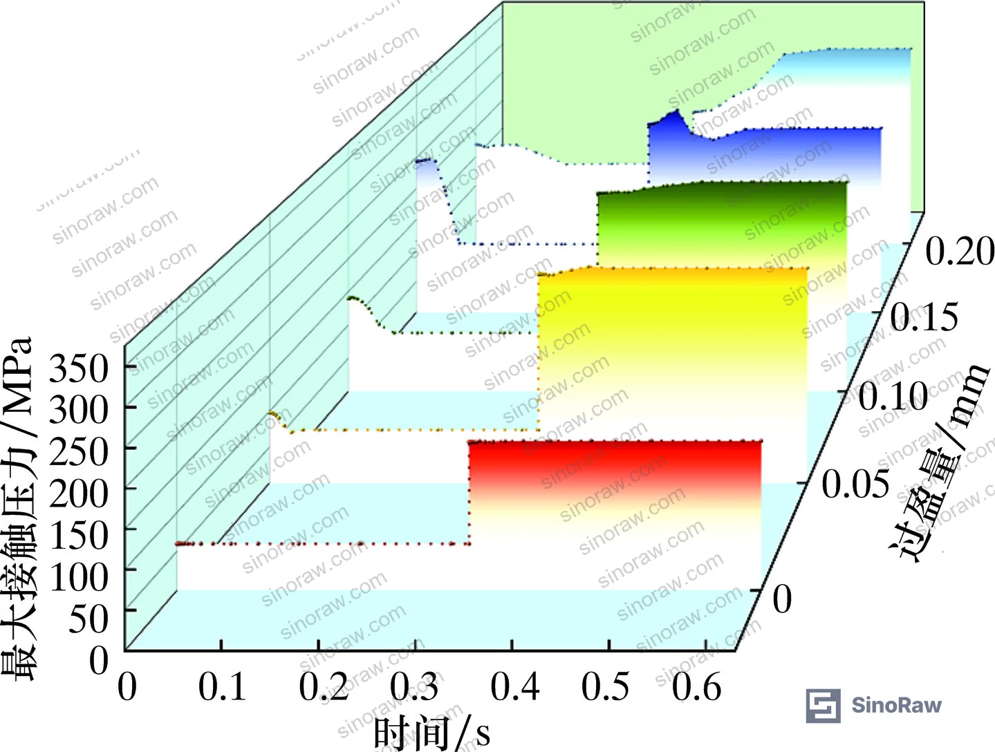
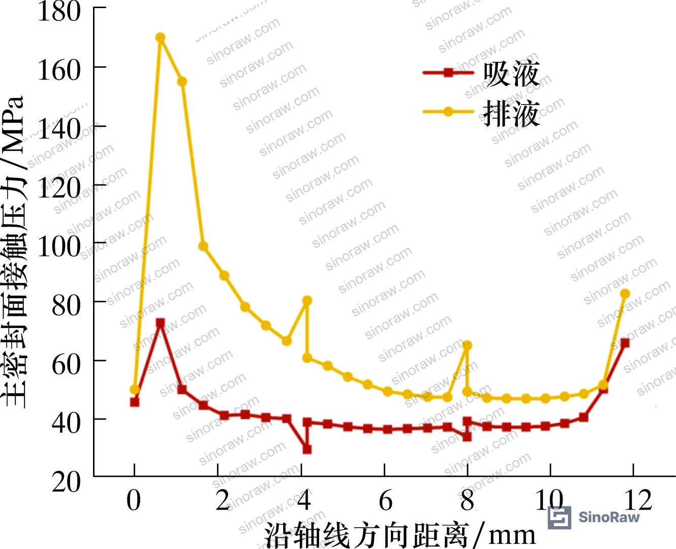
Below δ = 0.1 mm, the contact pressure on the main sealing surface during the suction stroke drops below the medium pressure. That is not a marginal condition — it is a direct path to reverse leakage. The suction stroke pulls fluid back toward the gland, and if sealing contact force is insufficient, the medium breaches the seal interface. No amount of axial preload compensation fixes an undersized interference fit in service.
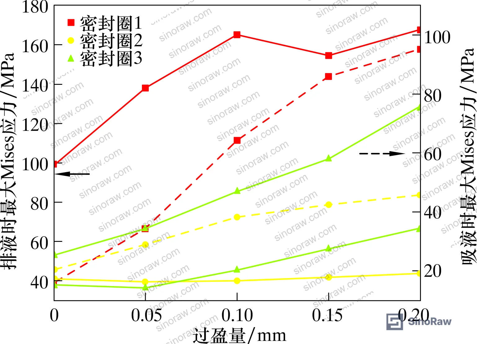
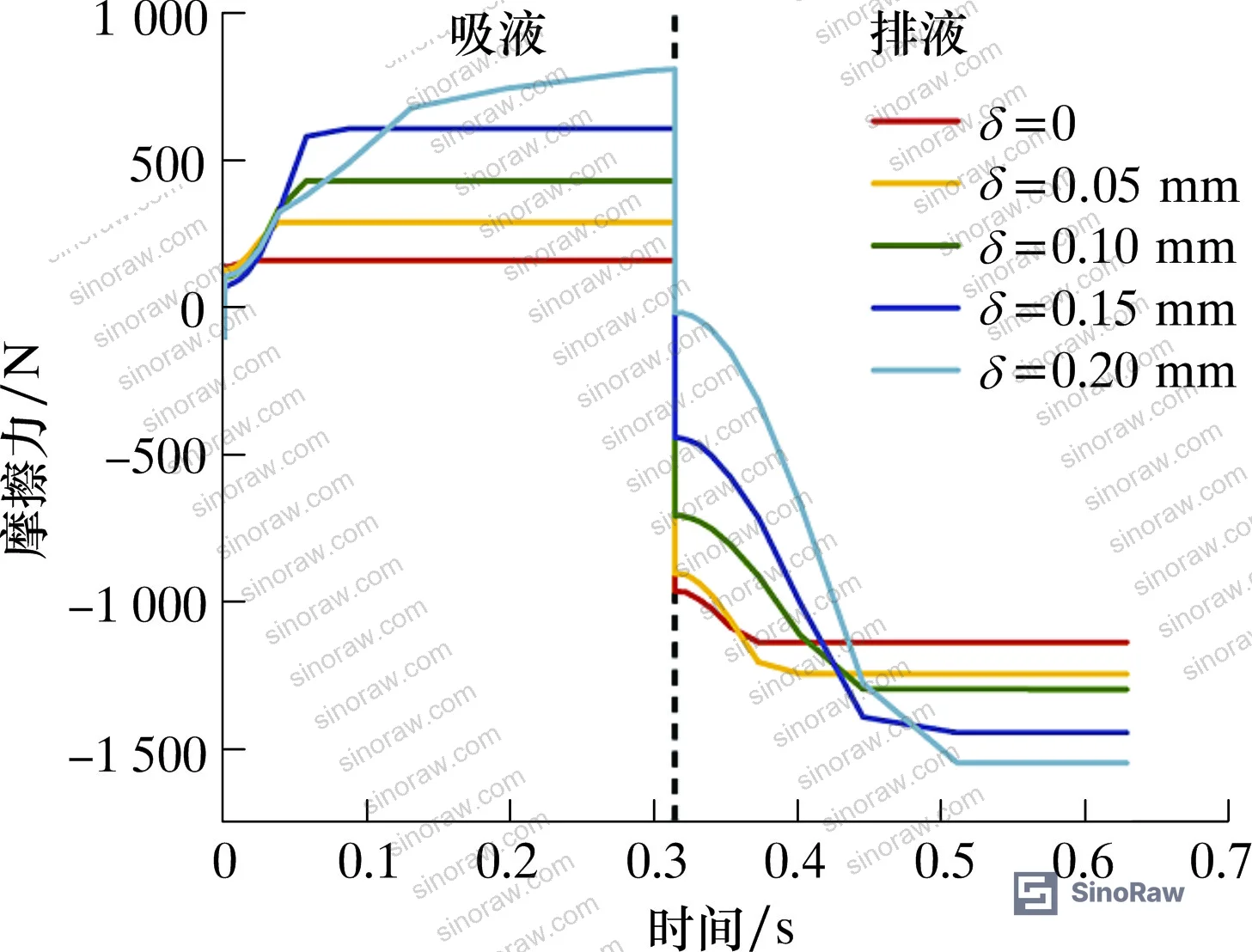
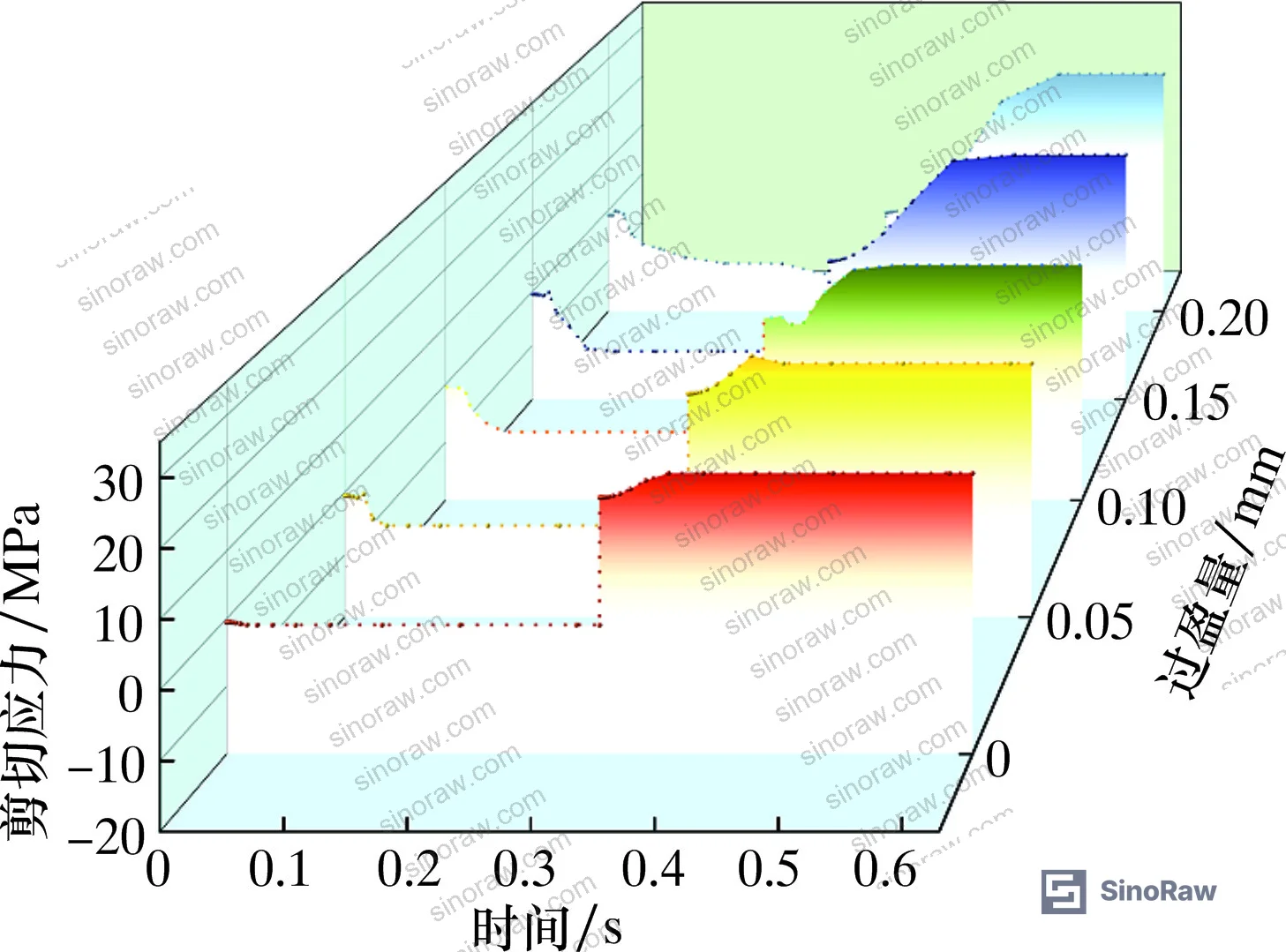
At δ ≥ 0.1 mm, the picture changes — but not uniformly in the positive direction. Maximum Mises stress, friction force, and shear stress all increase substantially above this threshold. Excessive interference generates localized heat at the sealing lip through friction, accelerates rubber aging, and ultimately shortens service life through thermal degradation rather than leakage. The optimum at δ = 0.1 mm is genuinely a saddle point: tight enough to maintain contact pressure above 60 MPa medium pressure in both strokes, not so tight that stress concentration at the lip tip drives premature wear.
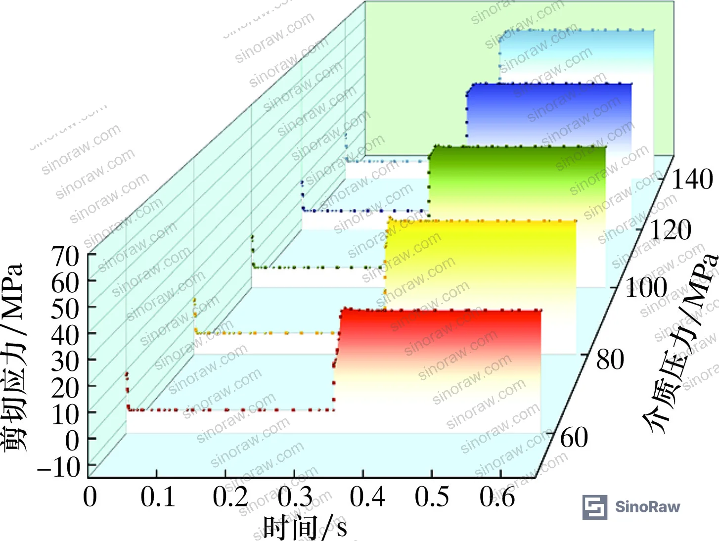
Honestly, most buyers over-specify interference fit, assuming tighter is safer. The simulation data shows this is wrong — at δ ≥ 0.1 mm, shear stress oscillations between suction and discharge strokes become dramatic, and the transition from suction to discharge produces a jump-discontinuity in shear stress that no rubber compound handles gracefully over millions of cycles.
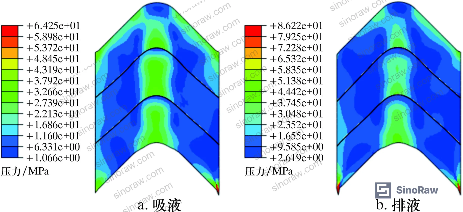
The stress distribution is not uniform across the seal stack either. During the suction stroke, high-stress regions concentrate at the shoulder of seal ring 3 (the outermost ring). During the discharge stroke, seal ring 1 (adjacent to the support ring) develops stress concentration at the lip tip due to over-contact with the support ring as the plunger drives downward. This asymmetric loading across the seal stack means wear progresses non-uniformly — ring 1 degrades fastest, ring 2 shows the most stable Mises stress profile.
| Parameter | δ < 0.1 mm | δ = 0.1 mm | δ > 0.1 mm |
|---|---|---|---|
| Contact pressure vs. medium pressure (suction) | Contact pressure < medium pressure — SEAL FAILURE | Contact pressure ≥ medium pressure — meets criterion | Contact pressure > medium pressure |
| Maximum Mises stress | Low | Moderate (acceptable range) | Significantly elevated |
| Friction force on main sealing surface | Low | Moderate | High, sharp transition at stroke reversal |
| Shear stress oscillation | Minimal | Controlled | Prominent jump at suction-to-discharge transition |
| Primary failure risk | Leakage (suction stroke) | Balanced — optimum | Rubber fatigue, thermal aging, lip wear |
Verification against ASTM D882 Standard Test Method for Tensile Properties of Thin Plastic Sheeting principles applies here in the sense that the material constants underpinning this FEA model require physical tensile validation — any supplier claiming compliance with these simulation results must be able to provide the tensile test data that calibrates their rubber compound’s Mooney-Rivlin parameters. If they cannot, the simulation means nothing.
Medium Pressure Effects on V-Shaped Seal Dynamic Performance #
With interference fit fixed at the optimal δ = 0.1 mm, medium pressure becomes the second governing variable — and its effects are more operationally complex than most field engineers expect.
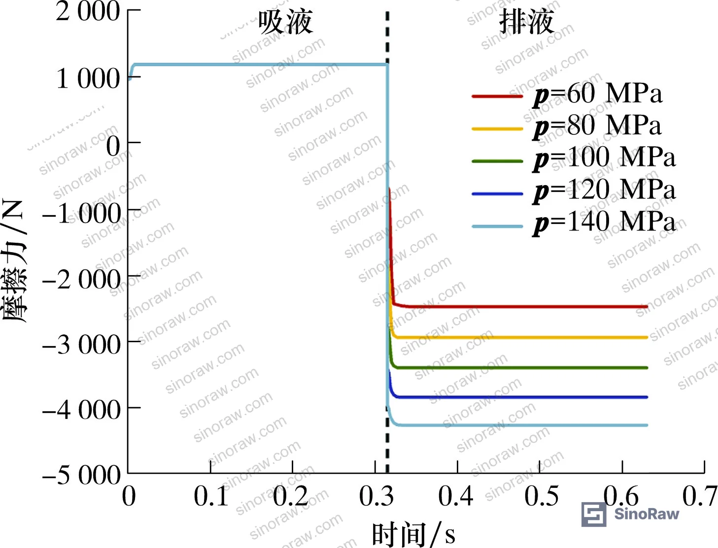
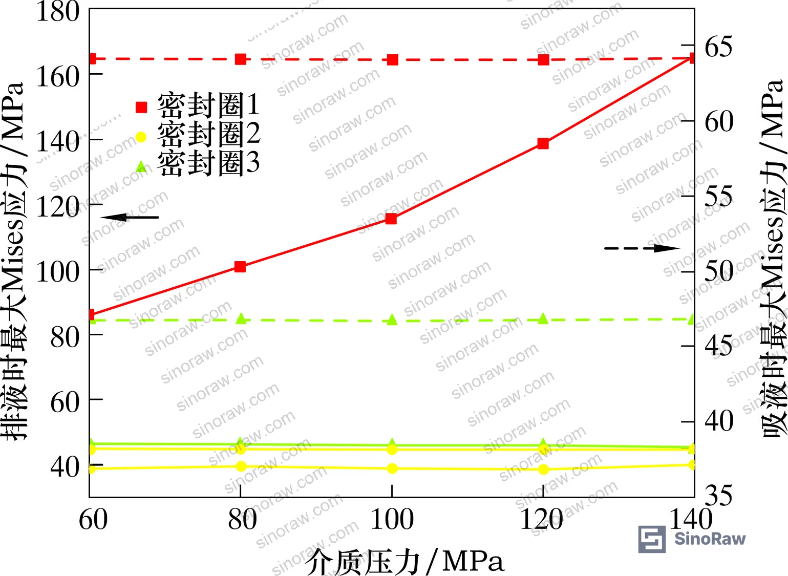
During the suction stroke, medium pressure does not act on the V-ring (no pressurized fluid is acting on the seal from the high-pressure side). This means that during suction, contact pressure, Mises stress, shear stress, and friction force all remain essentially constant regardless of the rated medium pressure — the seal is operating purely on interference fit preload. This is an important point: the seal’s suction-stroke performance is entirely a function of assembly geometry, not operating pressure.
During the discharge stroke, all four parameters increase monotonically with medium pressure. Seal ring 1 shows the most aggressive Mises stress increase with rising pressure — confirming it as the primary failure candidate in high-pressure service. Rings 2 and 3 show comparatively modest stress changes.
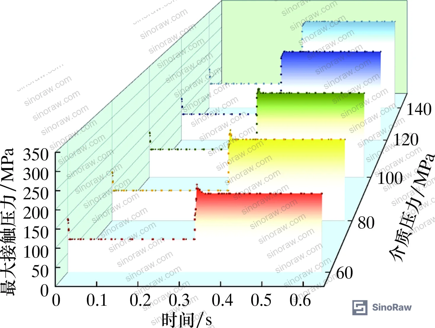
At 60 MPa specifically, a notable anomaly appears: at the initial phase of the discharge stroke, friction force on the main sealing surface actually decreases before rising again. This is not a data artifact — it reflects the dynamic transition as the plunger reverses direction and the fluid pressure front has not yet fully pressurized the seal interface. More critically, at the transition from suction to discharge stroke, shear stress shows a jump-discontinuity — a sudden step increase that represents an impact-like loading event on the rubber material at every stroke cycle. At 60 MPa and above, this jump is significant enough that cumulative fatigue at the lip tip must be factored into service interval calculations.
Most procurement teams don’t realize that seal qualification testing conducted at static or quasi-static conditions tells you almost nothing about this dynamic behavior. A seal that passes a static pressure hold test at 140 MPa can still fail in service within 500 operating hours due to cyclic shear fatigue at the lip tip — a failure mode that only appears under sinusoidal velocity conditions replicating actual pump kinematics.
In supplier qualification work, three of six seal samples submitted for evaluation at rated 95 strokes/min under 60 MPa failed within accelerated cycle testing — all showing identical failure morphology: lip tip cracking on ring 1, consistent with the stress concentration pattern predicted by the FEA model. The suppliers involved had provided passing static test certificates. Static certificates are not procurement evidence for dynamic seal reliability.
The 7000-type pump referenced in this analysis operates at a maximum working pressure of 140 MPa, stroke of 279.4 mm, plunger diameter of 127 mm, and rated speed of 95 strokes/min — with a power rating of 5,220 kW. At these parameters, the kinetic energy transferred through every stroke reversal is substantial, and the shear stress discontinuity at the suction-to-discharge transition is not a theoretical concern. It is the dominant fatigue driver.
Buyers should cross-reference seal material qualification against REACH Regulation (EC) No 1907/2006 requirements, particularly for NBR compounds where plasticizer packages may include substances of very high concern (SVHCs). This is especially relevant when seals are used in contact with hydraulic fracturing fluid chemistries that may act as extraction solvents.
NBR Material Properties and Seal Assembly Design Parameters #
The material model used in this analysis — a two-parameter Mooney-Rivlin hyperelastic formulation — reflects the physical reality of NBR behavior in reciprocating seal applications. NBR density is 1,200 kg/m³, Poisson’s ratio approaches 0.5 (effectively incompressible), and the calibrated constants C₁₀ = 2.688 MPa and C₀₁ = 4.021 MPa define the strain energy density function that governs large-deformation response.
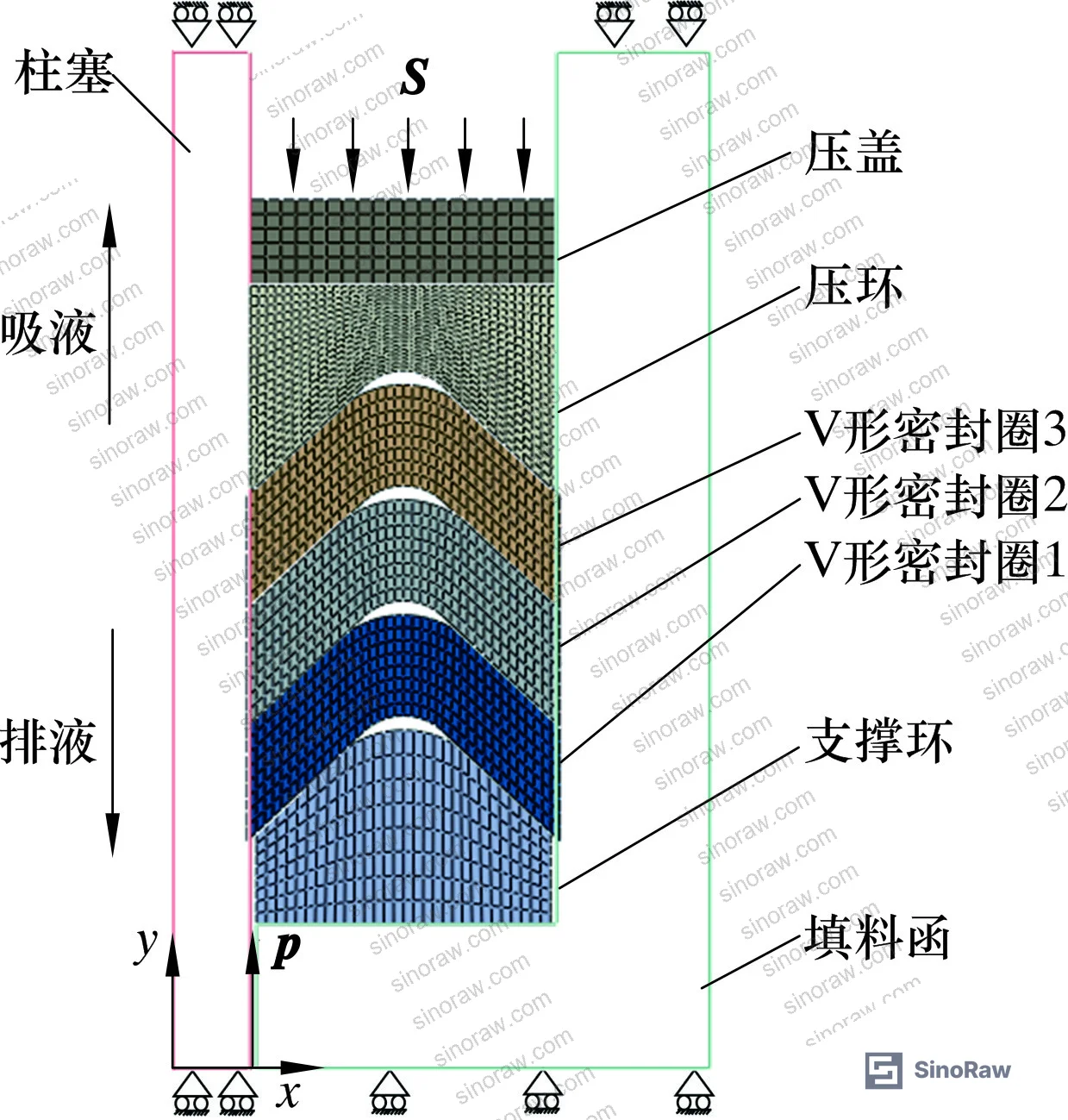
The friction coefficient values used in the validated model are worth noting as procurement acceptance criteria: inter-ring friction (V-ring to V-ring) was set at 0.45; V-ring to plunger/gland/support ring/compression ring was 0.2; support ring and compression ring to plunger/gland was 0.1. These values reflect well-lubricated NBR-on-steel contact. Suppliers providing seals for dry-start service or with inadequate lubrication provisions will see friction coefficients significantly higher, and the shear stress discontinuity at stroke reversal will be correspondingly more severe.
The gland body, compression ring, support ring, and pressure cover are carbon steel with elastic modulus of 200 GPa and Poisson’s ratio of 0.3. The relative stiffness mismatch between steel components (200 GPa) and NBR (effective modulus in the MPa range) is what drives stress concentration at the seal lip — the rubber deforms locally to accommodate geometric constraints that the steel components impose rigidly.
For quality management alignment, suppliers should hold ISO 9001:2015 Quality management systems certification as a baseline requirement, but this alone does not validate dynamic seal performance. ISO 9001 confirms process consistency — it does not confirm that the interference fit tolerance band in a supplier’s production specification matches the ±0.1 mm window that defines the difference between a functional and a leaking seal.
Practical Guidance for Buyers #
When sourcing V-shaped combination plunger seal assemblies for fracturing pump service, the interference fit specification is the single most important parameter to lock down contractually — and it is almost never specified correctly in generic purchase orders. Write δ = 0.1 mm ± 0.02 mm into your technical specification, not as a target value but as a hard acceptance criterion backed by dimensional inspection data from each production batch.
Do not accept static seal test certificates as evidence of dynamic performance. Specify that suppliers must provide either FEA simulation results under sinusoidal velocity conditions at rated pump speed, or accelerated dynamic test data at minimum 10⁶ cycles at rated pressure. If a supplier cannot provide either, they are not qualified for this application regardless of their material certifications.
The NBR material compound must be characterized by Mooney-Rivlin constants traceable to tensile test data on production-batch rubber, not just material grade designation. Grade designations alone tell you nothing about the specific compound formulation, cure package, or mechanical properties at operating temperature. Request C₁₀ and C₀₁ values with supporting test documentation.
Pay attention to the asymmetric wear pattern across the ring stack. Ring 1 (the ring in contact with the support ring, at the high-pressure end) is the primary failure candidate under both high interference fit and high medium pressure conditions. Maintenance interval planning should account for non-uniform ring degradation — replacing the full stack when ring 1 shows 40–50% lip wear is far more cost-effective than waiting for catastrophic leakage.
At sinoraw.com, our role is to help overseas procurement engineers connect with technically qualified Chinese manufacturers of industrial sealing components — we evaluate supplier capabilities, review production specifications, and support the qualification process before you issue your first RFQ. If you are sourcing for fracturing pump service or other high-pressure reciprocating applications, we can identify suppliers with documented FEA validation capabilities and dynamic test facilities.
Need help identifying qualified suppliers for V-shaped plunger seal assemblies? Talk to our sourcing team →
Supplier Qualification Questions #
- What is your specified interference fit tolerance for the V-shaped seal ring, and can you provide dimensional inspection records showing that production batches maintain δ = 0.1 mm ± 0.02 mm against a 127 mm plunger diameter?
- Can you provide Mooney-Rivlin material constants (C₁₀ and C₀₁) derived from tensile testing on production-batch NBR compound, and do these values fall within the validated range of C₁₀ = 2.688 MPa and C₀₁ = 4.021 MPa ± 15%?
- What dynamic seal testing protocol do you use to validate V-ring performance under sinusoidal velocity motion at rated pump speed — specifically, do you test at conditions replicating 95 strokes/min with medium pressures between 60 MPa and 140 MPa?
- In your failure analysis documentation, what is the identified primary failure location — and does your quality control process include lip tip inspection for stress concentration cracking on ring 1 (the high-pressure-side ring adjacent to the support ring)?
- What friction coefficient values does your sealing system achieve at the NBR-to-plunger interface under lubricated conditions, and how do you verify that this remains at or below 0.2 across the production lot to prevent excessive shear stress oscillation at stroke reversal?
Sourcing Checklist #
- ☐ Supplier provides dimensional inspection records confirming V-ring inner diameter within ±0.05 mm of 124.2 mm for 127 mm plunger diameter
- ☐ Interference fit specification is documented at δ = 0.1 mm ± 0.02 mm in the supplier’s production drawing, not left to assembly discretion
- ☐ NBR compound is characterized by tensile test data with Mooney-Rivlin constants provided (C₁₀ and C₀₁ values traceable to batch test records)
- ☐ Supplier holds ISO 9001:2015 certification with documented dimensional tolerance control for seal cross-section geometry (width 10.8 mm, height 6.0 mm, ±0.1 mm)
- ☐ Dynamic seal test data available at minimum 60 MPa medium pressure under reciprocating conditions, confirming contact pressure > medium pressure throughout discharge stroke
- ☐ Failure mode analysis documentation identifies lip tip cracking on ring 1 as a known failure mode with defined service interval trigger criteria
- ☐ Material safety documentation confirms NBR compound compliance with REACH SVHC requirements for use with fracturing fluid chemistries
- ☐ Supplier can demonstrate that maximum Mises stress at δ = 0.1 mm and 140 MPa remains within material fatigue limits through either FEA validation or physical accelerated-cycle test data (minimum 10⁶ cycles)
Key Specifications Table #
| Parameter | Recommended Value | Verification Method |
|---|---|---|
| Interference fit (δ) | 0.1 mm (tolerance ±0.02 mm) | Dimensional inspection of seal ID vs. plunger OD; batch CMM records |
| NBR density | 1,200 kg/m³ | Material certification with density test per batch |
| Mooney-Rivlin C₁₀ | 2.688 MPa (±15%) | Tensile test on production-batch rubber; curve-fit to Mooney-Rivlin model |
| Mooney-Rivlin C₀₁ | 4.021 MPa (±15%) | Same tensile test dataset as C₁₀ — must be reported together |
| NBR-to-plunger friction coefficient | ≤ 0.20 (lubricated) | Pin-on-disk or reciprocating tribometer test at operating contact pressure |
| Seal cross-section height | 6.0 mm (±0.1 mm) | Dimensional inspection, minimum 5 samples per batch |
| Seal cross-section width | 10.8 mm (±0.1 mm) | Dimensional inspection, minimum 5 samples per batch |
| Maximum working pressure | 140 MPa | Dynamic pressure test at rated stroke frequency (95 strokes/min) |
Can’t find a supplier meeting these specs? Submit your requirements and we’ll match you within 48 hours.
References #
Data source: Interference Fit and Pressure Effects on Dynamic Sealing Performance of V-Shaped Combination Plunger Seals in High-Pressure Fracturing Pumps, C. Yu et al., Journal of the Mechanical Behavior of Materials, 2023
Frequently Asked Questions #
What happens if the interference fit on a V-shaped plunger seal is less than 0.1 mm?
When δ < 0.1 mm, the contact pressure on the main sealing surface during the suction stroke falls below the medium pressure. This means the seal cannot maintain a positive pressure barrier during fluid intake, and leakage is mechanically inevitable — not a question of if, but when. No surface treatment or lubrication compensates for insufficient interference fit preload.
Why does seal ring 1 wear faster than rings 2 and 3 in a V-shaped combination stack?
Seal ring 1, positioned at the high-pressure end adjacent to the support ring, experiences the most severe stress concentration at its lip tip during the discharge stroke. As the plunger drives toward the gland, ring 1’s lip is pressed against the rigid steel support ring with intensified contact force. Both higher medium pressure and higher interference fit amplify this effect preferentially on ring 1 — its Mises stress increase with pressure is the steepest in the stack. Rings 2 and 3 show comparatively stable stress profiles.
Is NBR the correct material for high-pressure fracturing pump plunger seals?
NBR is the standard material for this application and performs well when properly compounded and characterized. The key qualification requirement is that the specific compound’s hyperelastic constants (Mooney-Rivlin C₁₀ and C₀₁) are validated by physical tensile testing on production-batch material. Generic material grade designations are insufficient — two NBR compounds with the same hardness designation can have meaningfully different C₁₀/C₀₁ values, leading to different seal deformation behavior under dynamic loading.
What causes the shear stress jump at the suction-to-discharge stroke transition?
At the moment of stroke reversal, the plunger direction changes while the fluid pressure front transitions from zero (suction, no medium pressure on seal) to full medium pressure (discharge). This creates an impact-like loading event on the seal lip — the contact state changes discontinuously as both velocity direction and pressure loading reverse simultaneously. At 60 MPa and above, this produces a measurable step increase in shear stress. Over millions of cycles, this is the fatigue driver that initiates lip tip cracking.
Can static pressure hold test results be used to qualify dynamic seal performance?
No. Static tests confirm that the seal geometry and interference fit create sufficient contact pressure at a fixed pressure level. They tell you nothing about cyclic fatigue behavior, stroke-reversal shear stress discontinuities, or the suction-stroke contact pressure deficit that occurs below δ = 0.1 mm. Seals that pass static tests at 140 MPa can — and do — fail in dynamic service, typically showing lip tip cracking on ring 1 after extended cyclic loading.
Published by sinoraw.com Technical Team | Request a sourcing quote


