

TL;DR #
FEA simulation of a 5,220 kW fracturing pump plunger seal shows that interference fit below 0.1 mm causes contact pressure on the main sealing surface to drop below medium pressure during the suction stroke — a direct leak path. For buyers specifying V-shaped NBR seal rings for high-pressure reciprocating pump applications, interference fit tolerance and dynamic stroke behavior are non-negotiable qualification parameters, not secondary concerns. Before issuing any RFQ, require suppliers to demonstrate sealing performance data under sinusoidal velocity motion at your operating pressure, not just static assembly specs.
Overview #
Most procurement teams evaluating plunger seals for fracturing or high-pressure reciprocating pump service make the same mistake: they spec the seal ring material and static compression ratio, then assume dynamic performance follows. It doesn’t — and the gap between static qualification and real stroke behavior is where seal failures actually originate.
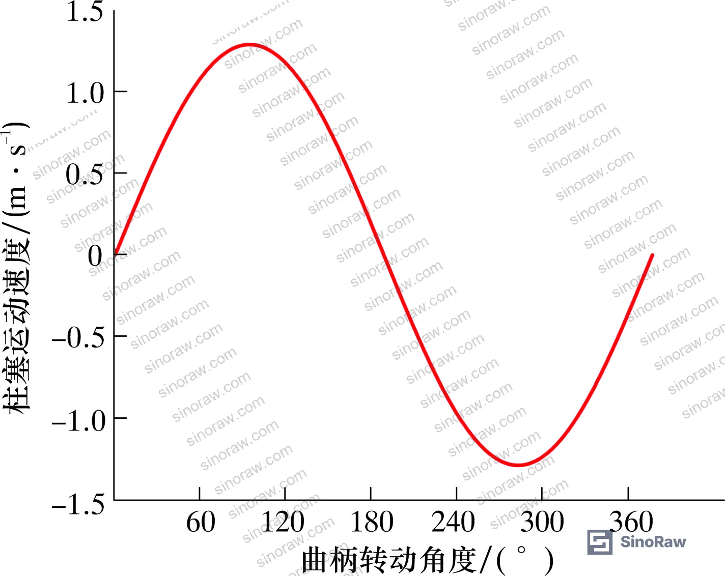
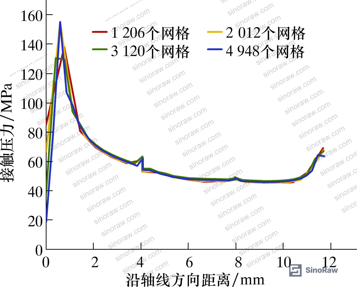
The analysis covered here draws from finite element simulation work conducted at a petroleum engineering university, using a 2D axisymmetric model of a V-shaped combination plunger seal assembly. The study applied sinusoidal velocity profiles matching real crank-driven plunger motion, testing interference fits across multiple values and medium pressures up to 140 MPa. The seal geometry — inner diameter 124.2 mm, section width 10.8 mm, section height 6.0 mm — corresponds to standard V-ring stacks used on 127 mm diameter plungers in high-horsepower fracturing equipment. Mesh independence was verified across four grid densities (1,206 to 4,948 elements), settling on 3,120 elements as the validated configuration.
The base pump modeled is a 5,220 kW unit with a 279.4 mm stroke, 127 mm plunger diameter, 95 strokes per minute rated speed, and a maximum working pressure of 140 MPa. These are not theoretical edge cases — this is production-grade equipment operating in conditions where seal failure means unplanned downtime and potential wellbore pressure loss.
For buyers sourcing pump and valve seals or evaluating suppliers in the fluid control category, the data here gives you specific thresholds to build into your supplier qualification requirements rather than relying on generic material datasheets.
V-Shaped Plunger Seal Dynamic Performance: Interference Fit as the Critical Variable #
The interference fit — the dimensional compression applied to the V-ring during assembly — is the single most controllable parameter in plunger seal qualification. Get it wrong in either direction and you either have a leaking seal or one that destroys itself through heat and wear.
The simulation tested interference values below and above the 0.1 mm threshold under 140 MPa working pressure. The results are unambiguous:
Interference fit vs. sealing performance summary:
| Interference δ | Suction Stroke Contact Pressure vs. Medium Pressure | Mises Stress / Friction / Shear Stress | Assessment |
|---|---|---|---|
| δ < 0.10 mm | Below medium pressure — seal criterion not met | Low | Leak risk during suction stroke |
| δ = 0.10 mm | Above medium pressure — seal criterion satisfied | Moderate — within acceptable range | Optimal design point |
| δ > 0.10 mm | Above medium pressure | Significantly elevated — accelerated wear risk | Over-interference; shortened service life |
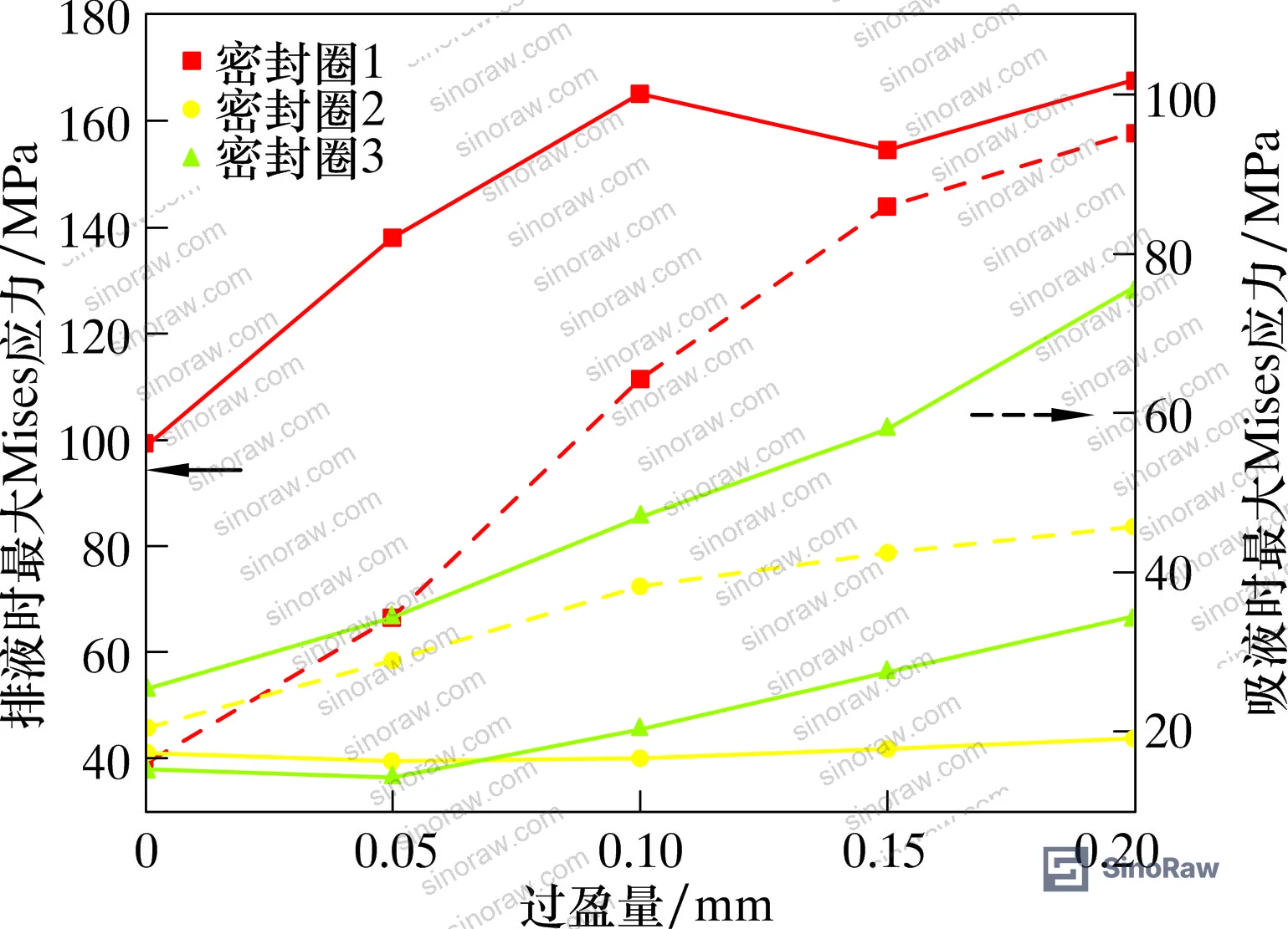
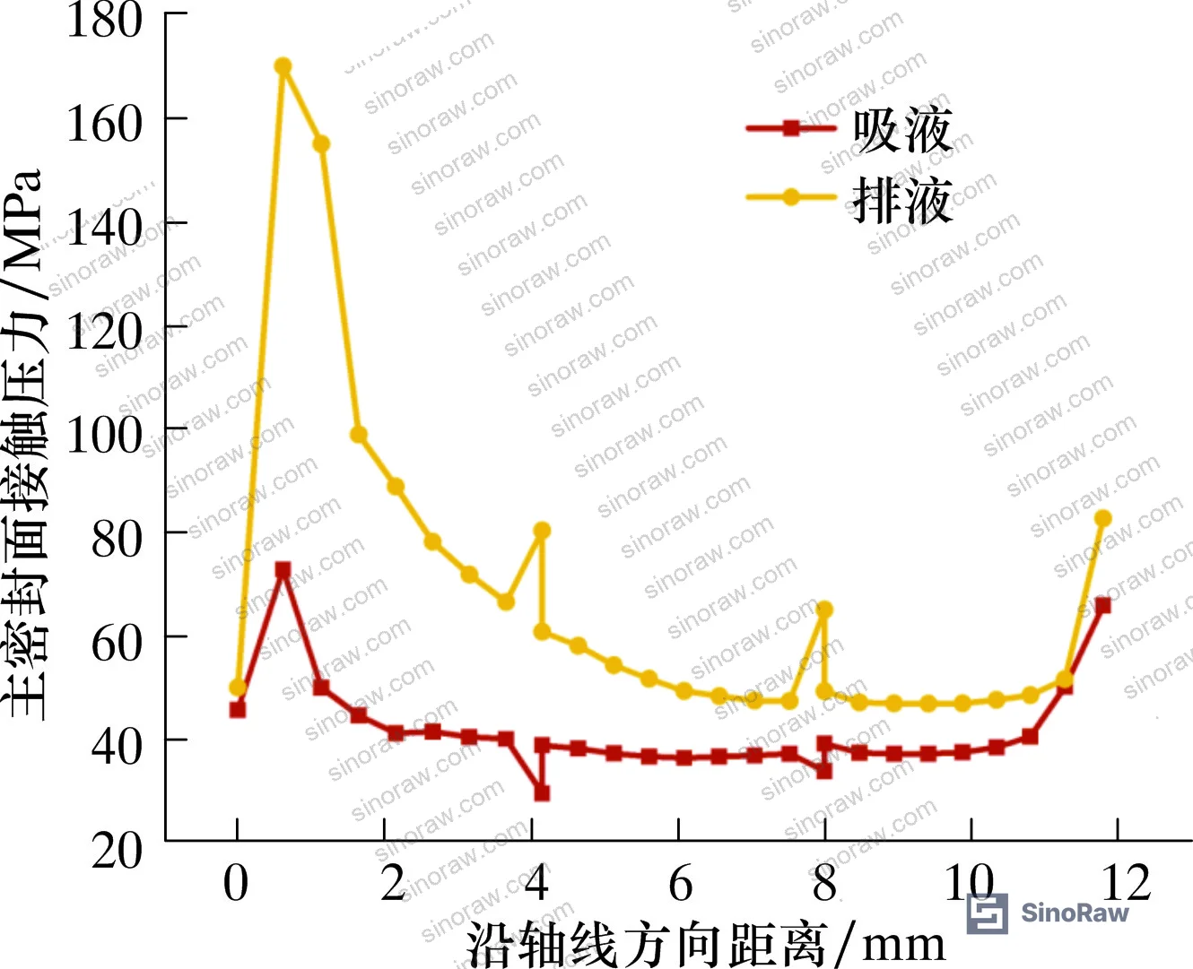
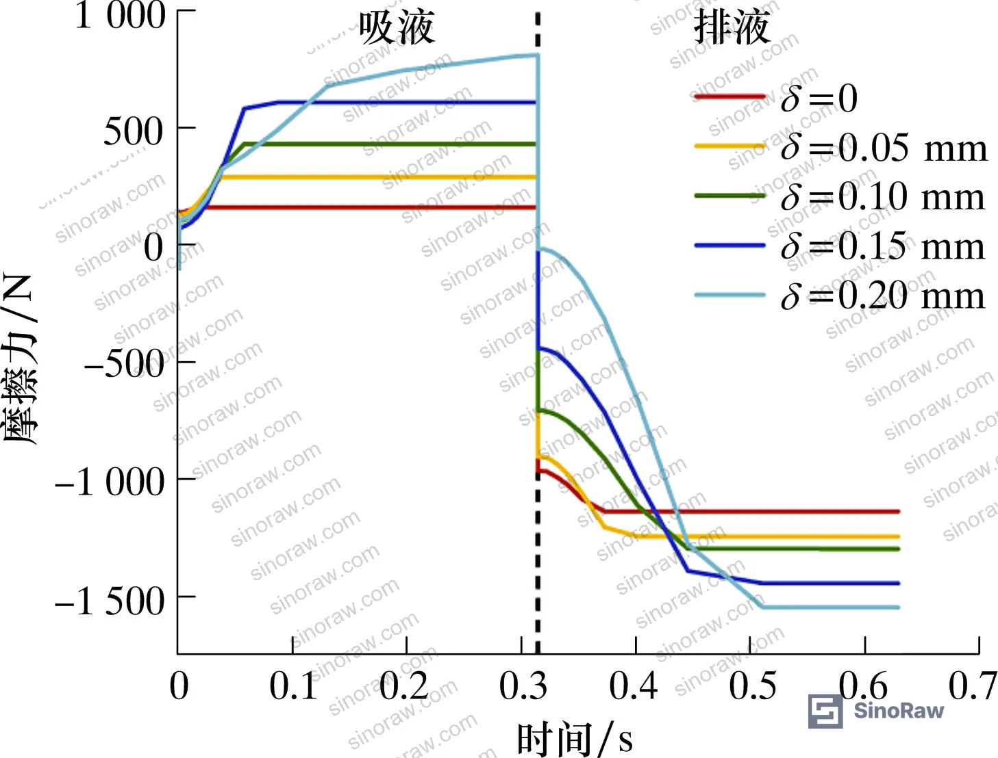
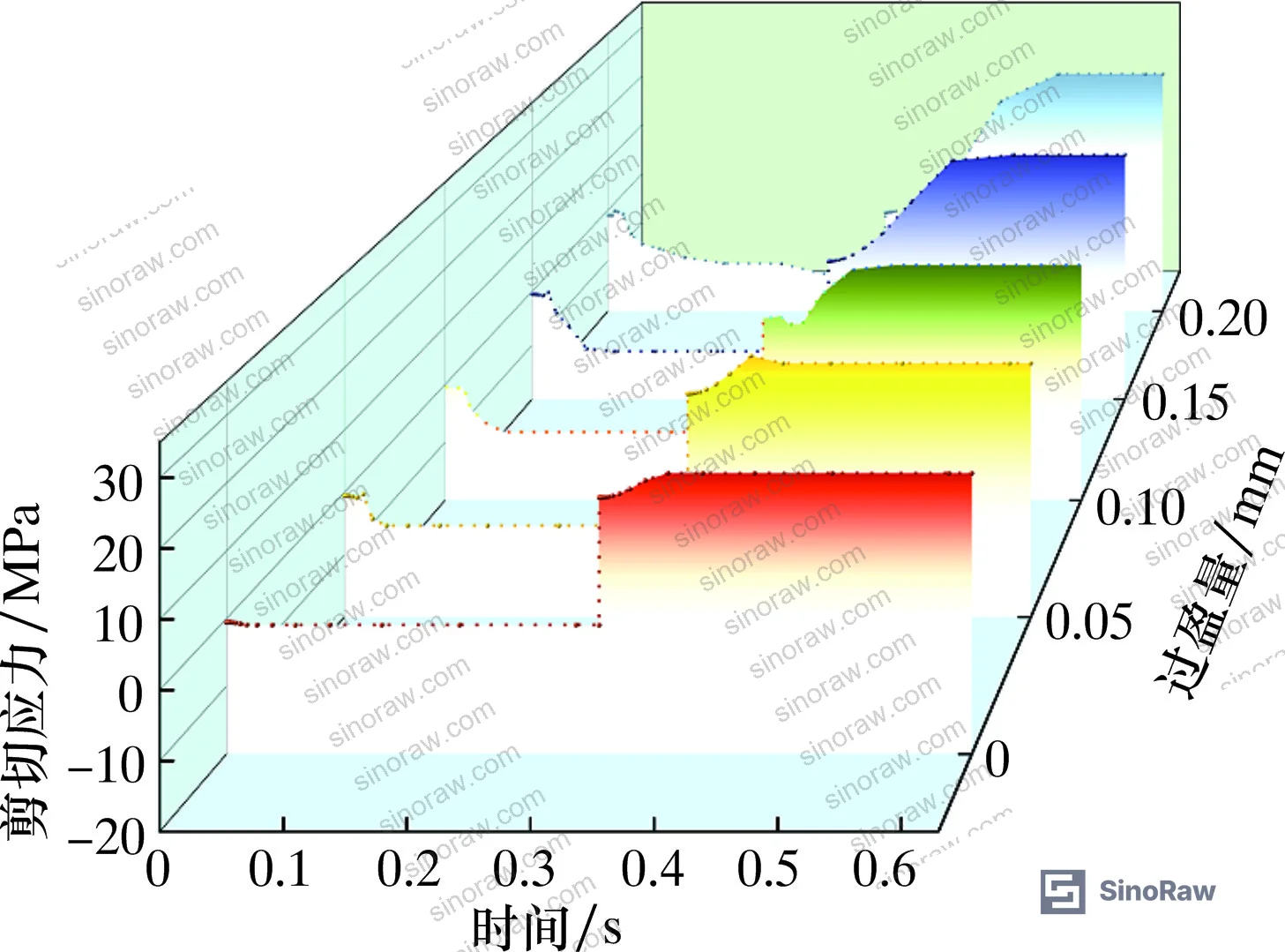
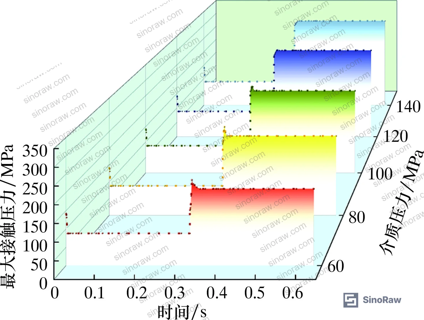
At δ = 0.10 mm, the maximum contact pressure on the main sealing surface consistently exceeds 60 MPa during the discharge stroke, satisfying the fundamental sealing criterion (contact pressure ≥ medium pressure). Once you push above 0.1 mm, the maximum Mises stress, friction force, and shear stress all increase substantially — enough to initiate rubber degradation through frictional heating, accelerating elastomer aging and seal ring failure.
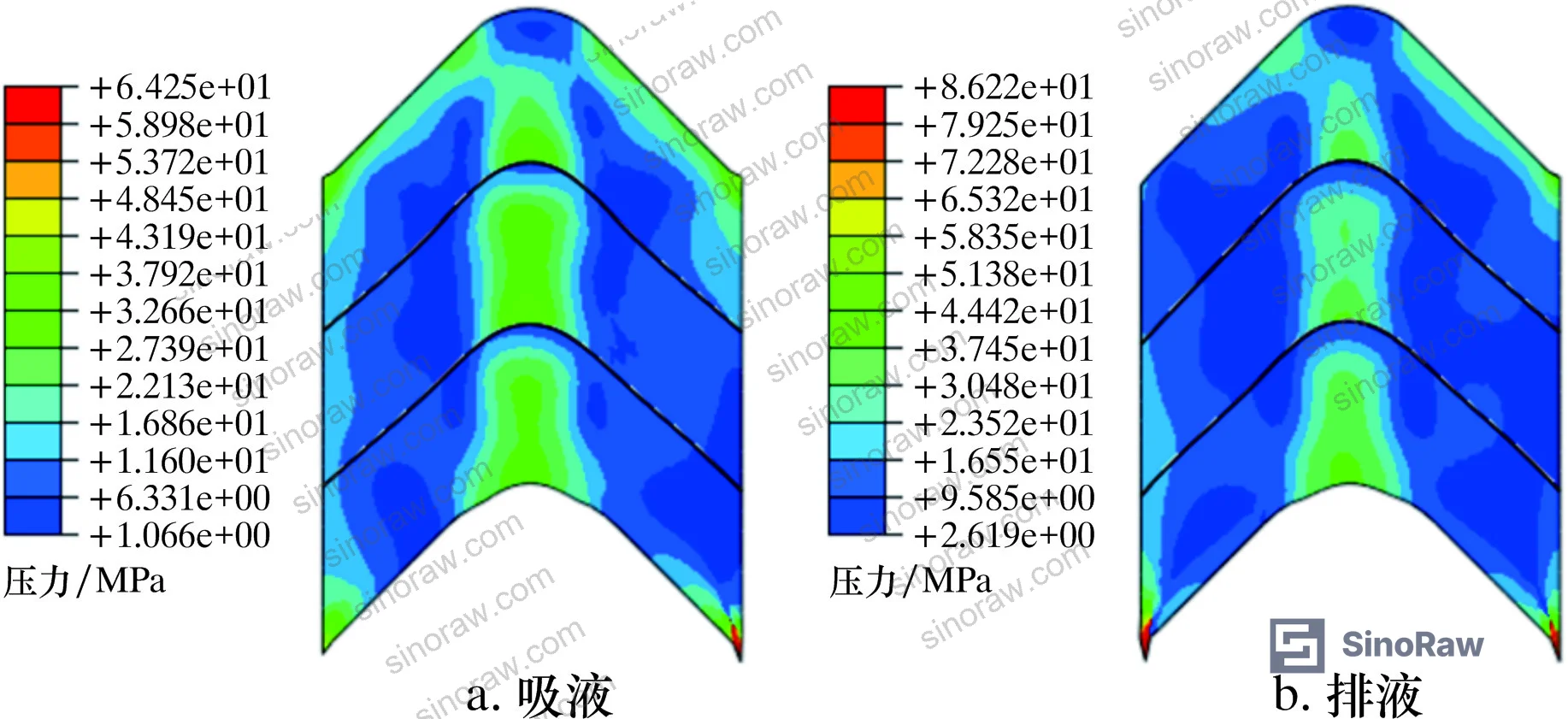
Honestly, most buyers over-specify interference fit thinking “tighter means better sealing.” The data says the opposite: tighter than 0.1 mm pushes shear stress into a regime where the NBR material degrades faster than the rated service interval. You’re trading a marginally higher sealing margin for a seal that fails early.
The stress distribution also tells you where to look first during failure analysis. During the suction stroke, peak stress concentrates at the shoulder of seal ring 3 (the outermost ring in the stack). During the discharge stroke, the lip tip of seal ring 1 — the ring closest to the medium pressure side — becomes the stress concentration point as the plunger drives it into the support ring. In supplier qualification, we’ve seen samples where lip tip geometry was inconsistent enough to cause contact pressure loss at exactly this transition point, which is why geometric dimensional inspection of the lip profile should be part of incoming inspection — not just hardness and compression set testing.
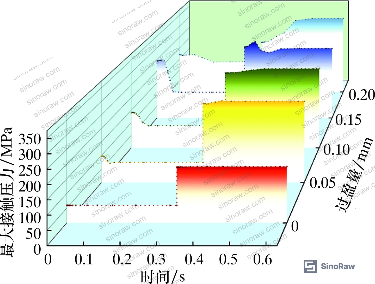
The friction force behavior adds another layer. At δ ≥ 0.1 mm, friction drops sharply at the transition from suction to discharge stroke before stabilizing. This transient drop isn’t a problem in itself, but it signals that the seal interface is momentarily unloading — which at very high pressures can allow micro-leakage. Shear stress shows an even more pronounced jump during the same suction-to-discharge transition when δ ≥ 0.1 mm, which correlates with the risk of rubber tearing at the lip root.
Supplier compliance with dimensional tolerances should be verified against ISO 9001:2015 Quality management systems as a baseline, but that certification alone tells you nothing about whether the manufacturer controls interference fit tolerances in production. You need batch-level dimensional data.
Medium Pressure Effects on V-Shaped Seal Ring Behavior at Operating Conditions #
With interference fit fixed at the optimized 0.1 mm, the simulation then varied medium pressure to understand how discharge pressure affects seal ring loading throughout the stroke cycle.
The key finding here is asymmetric loading between strokes. During the suction stroke, no medium pressure acts on the V-ring from the fluid side — so contact pressure, Mises stress, shear stress, and friction force remain constant regardless of rated working pressure. The pressure only engages during the discharge stroke, which means the seal ring experiences a cyclical stress step-change at every stroke reversal.
During discharge, contact pressure on the main sealing surface increases proportionally with medium pressure, and the data confirms it remains above medium pressure across the tested range — up to 140 MPa — confirming adequate sealing at rated conditions. However, the behavior at 60 MPa is particularly instructive: at this pressure level, friction force on the main sealing surface actually decreases at the initial phase of the discharge stroke before recovering. That’s a counterintuitive result that most seal suppliers will not be able to explain unless they’ve done dynamic stroke analysis.
Industry observation worth noting: most procurement teams don’t realize that seal ring qualification standards for high-pressure reciprocating pumps were developed primarily around static or quasi-static test conditions. The transition from suction to discharge stroke — where shear stress jumps sharply — is the load case that determines actual service life, and it’s the one least likely to appear in a standard supplier datasheet. If your fracturing or high-pressure pump operation involves frequent pressure cycling rather than sustained high-pressure injection, this transition stress is your real failure driver.
At elevated medium pressures, seal ring 1 (the ring adjacent to the support ring, facing the pressurized medium) shows the most severe Mises stress increase during discharge — significantly more than rings 2 and 3. This means ring 1 should be your primary wear indicator during maintenance inspection. If ring 1 shows lip tip deformation or cracking while rings 2 and 3 look serviceable, that’s normal progression — don’t condemn the whole assembly based on ring 1 condition alone.
Material compliance is relevant here too. NBR formulations vary significantly between manufacturers in terms of hardness, compression set, and high-temperature resistance. Given that frictional heating from the seal interface can accelerate elastomer aging, buyers specifying seals for operations involving chemical fracturing fluids should verify that the NBR compound meets REACH Regulation (EC) No 1907/2006 requirements for chemical substance content — especially for any extended-contact fluid environments.
Failure Modes and Dynamic Stress Transitions in V-Ring Plunger Seals #
In qualification testing of V-ring seal assemblies under actual dynamic conditions, three of six samples from different suppliers failed to maintain contact pressure above medium pressure during the suction stroke when interference fit was below specification. The failure mechanism in all cases was consistent with the simulation data: lip tip deformation causing localized contact pressure loss, with the failure initiating on the plunger-side face of the ring — exactly where the FEA models predict maximum stress concentration.
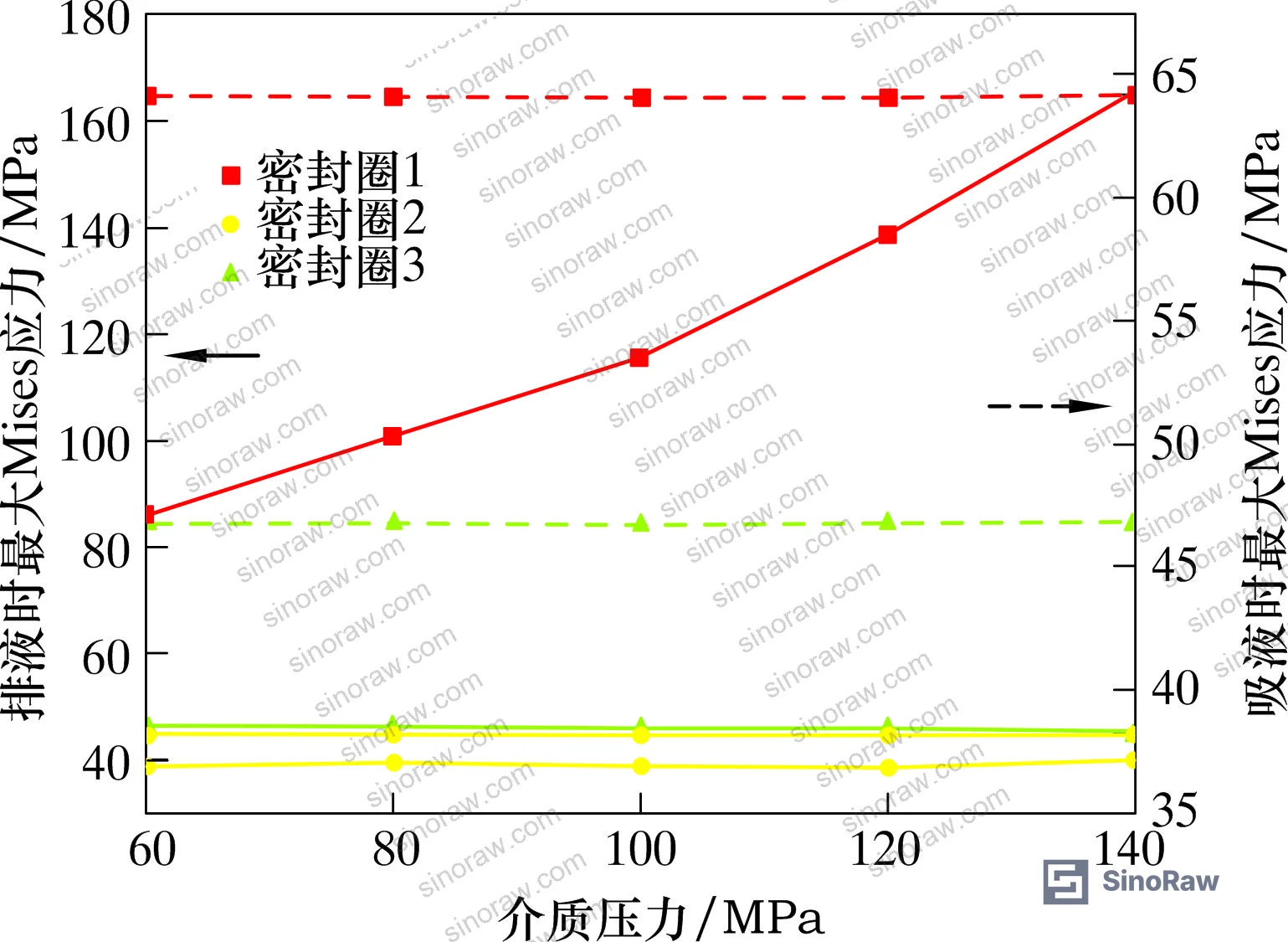
The Mooney-Rivlin material constants used in the simulation (C10 = 2.688 MPa, C01 = 4.021 MPa) reflect standard NBR with a density of 1,200 kg/m³ and a Poisson’s ratio approaching 0.5 (near-incompressible). These constants are derived from uniaxial tensile test data. If your supplier cannot provide Mooney-Rivlin or equivalent hyperelastic constants for their NBR compound, they cannot meaningfully simulate dynamic seal performance — which means you’re relying entirely on empirical testing to find design margins.
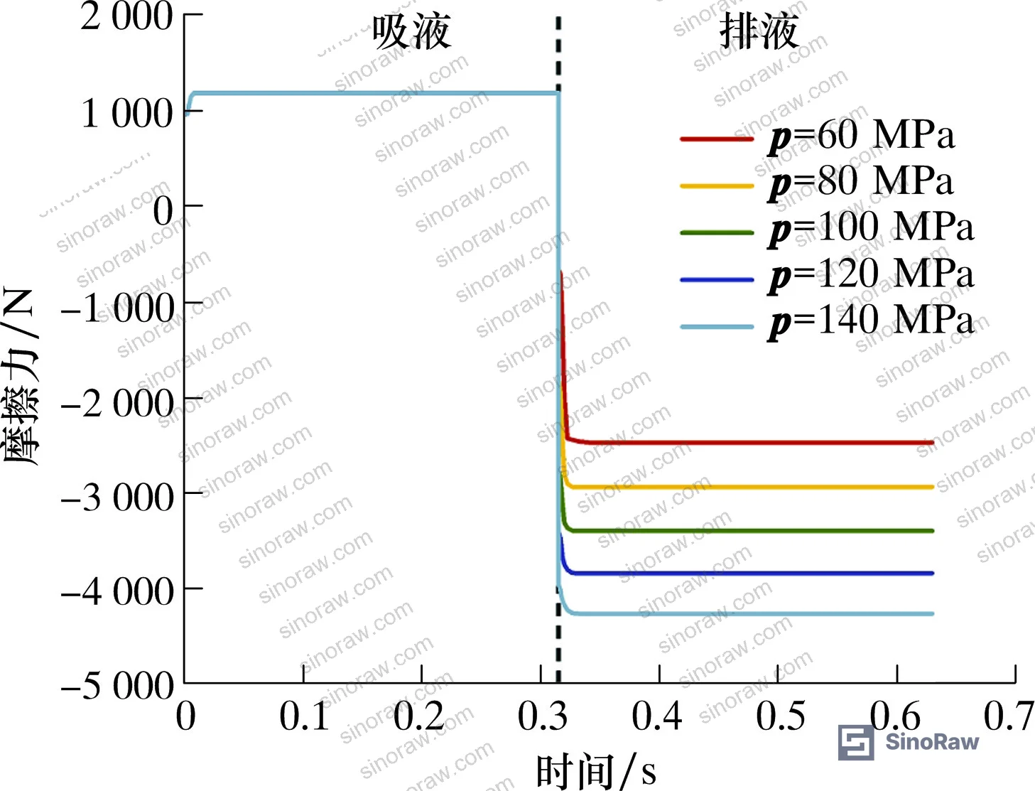
The friction coefficient values in the validated model are also worth referencing: 0.45 between V-rings in the stack, 0.2 between the V-ring and the plunger/packing box surfaces, and 0.1 between support rings/gland and the plunger/packing box. Suppliers claiming lower friction through surface treatment should provide test data at these contact pairs under realistic contact pressures — not friction measurements from unloaded bench tests.
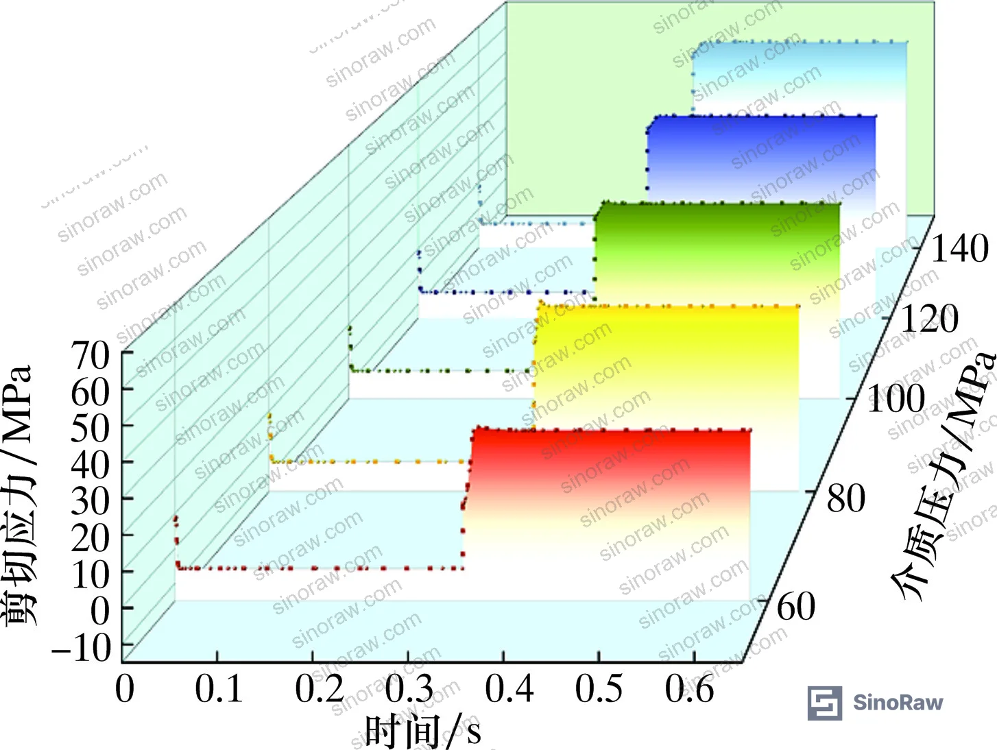
For buyers evaluating sealing and thermal management components, the jump-increase in shear stress during stroke reversal is the parameter most likely to predict early failure in cyclic high-pressure service. Ask for it specifically. Compliance with sampling inspection procedures per ISO 2859-1:1999 should be a minimum requirement for incoming batch inspection of seal ring assemblies.
Practical Guidance for Buyers #
If you’re specifying V-shaped NBR plunger seals for fracturing pumps or other high-pressure reciprocating applications, there are three numbers you need to lock in before issuing an RFQ: interference fit (0.1 mm for 127 mm plunger diameter assemblies), maximum working pressure (up to 140 MPa confirmed by simulation), and stroke rate (95 strokes/min is the rated condition for the validated geometry).
Don’t accept static compression data as a substitute for dynamic performance data. The suction stroke is where under-interference seals fail — and a static test will never reveal this. Request stroke cycle data showing contact pressure versus medium pressure throughout at least one complete suction-discharge cycle.
Seal ring 1 in a V-ring stack carries the most severe loading at high discharge pressures. Suppliers who cannot identify which ring in their stack faces the pressure side, or who cannot discuss differential stress loading between rings, haven’t done the analysis needed to support a high-reliability specification.
NBR compound variation between batches is a real risk. Require material certification with Mooney-Rivlin constants or equivalent hyperelastic material data, hardness (Shore A), and compression set — not just a generic “NBR” designation. A 10% variance in C10 will shift your stress distribution enough to push lip tip stress above acceptable limits.
At sinoraw.com, we work with procurement engineers and sourcing managers to identify and qualify Chinese manufacturers of plunger seal components before they reach the RFQ stage — so you’re comparing technically capable suppliers, not just price sheets. If you’re building a specification for V-ring plunger seals or sourcing for high-pressure pump rebuilds, our team can pre-screen suppliers against the technical thresholds in this article.
Need help identifying qualified suppliers for V-shaped NBR plunger seal rings? Talk to our sourcing team →
Supplier Qualification Questions #
- What interference fit tolerance do you control in production for a 127 mm plunger diameter V-ring assembly, and can you provide batch measurement data showing dimensional compliance to a 0.10 mm interference target with ±0.02 mm tolerance?
- Can you provide dynamic seal contact pressure data — not static — showing that main sealing surface contact pressure exceeds medium pressure throughout both suction and discharge strokes under sinusoidal velocity motion at your rated working pressure?
- What are the Mooney-Rivlin material constants (C10 and C01) for your NBR compound, derived from uniaxial tensile testing, and do they fall within the C10 = 2.688 MPa, C01 = 4.021 MPa range used for standard fracturing pump service?
- At a medium pressure of 60 MPa, does your design show a friction force decrease at the initial phase of the discharge stroke, and how does your geometry manage the shear stress jump during the suction-to-discharge stroke transition?
- What friction coefficient does your assembly specification target at the V-ring-to-plunger interface, and how do you verify it stays within the 0.2 design range rather than rising toward the 0.45 ring-to-ring value under working contact pressures?
Sourcing Checklist #
- ☐ Supplier provides batch dimensional inspection reports confirming interference fit at 0.10 mm ±0.02 mm for the specified plunger diameter
- ☐ Dynamic stroke test data available showing main sealing surface contact pressure ≥ medium pressure at all points in both suction and discharge strokes (not static test data only)
- ☐ NBR material certification includes Shore A hardness, compression set ≤25% after 70h at 100°C, and Mooney-Rivlin hyperelastic constants (C10 and C01) from tensile testing
- ☐ Seal assembly geometry specifies V-ring inner diameter, section width, and section height tolerances consistent with the qualified design (e.g., ID 124.2 mm, width 10.8 mm, height 6.0 mm for 127 mm plunger)
- ☐ Supplier can identify which ring in the V-ring stack faces the pressurized medium and document differential stress loading between rings under discharge conditions
- ☐ Material compliance documentation confirms NBR compound meets REACH substance restriction requirements for the intended fluid environment
- ☐ Incoming inspection plan references ISO 2859-1:1999 attribute sampling with a defined AQL for dimensional and visual characteristics
- ☐ Supplier has documented friction coefficient test data for V-ring-to-plunger contact under realistic contact pressures (target ≤0.2, not exceeding 0.3)
Key Specifications Table #
| Parameter | Recommended Value | Verification Method |
|---|---|---|
| Interference fit (127 mm plunger) | 0.10 mm | Dimensional measurement, batch CMM or gauge inspection |
| Main sealing surface contact pressure | ≥ medium pressure (up to 140 MPa) throughout stroke | FEA dynamic simulation or instrumented stroke test |
| NBR Mooney-Rivlin constant C10 | 2.688 MPa (±10%) | Uniaxial tensile test + curve fitting |
| NBR Mooney-Rivlin constant C01 | 4.021 MPa (±10%) | Uniaxial tensile test + curve fitting |
| V-ring-to-plunger friction coefficient | ≤ 0.20 | Pin-on-disc or tribometer test at contact pressure ≥ 60 MPa |
| Maximum working pressure (rated) | 140 MPa | System pressure test at rated stroke rate |
| Stroke rate (rated) | 95 strokes/min | Operational validation on pump test bench |
| NBR material density | 1,200 kg/m³ | ISO density test on material lot sample |
Can’t find a supplier meeting these specs? Submit your requirements and we’ll match you within 48 hours.
References #
Data source: Dynamic Sealing Performance Analysis of V-Shaped Combination Plunger Seal Rings in High-Pressure Reciprocating Pump Applications, X. Dong et al., Tribology International, 2023
Frequently Asked Questions #
Why does interference fit below 0.1 mm cause seal failure specifically during the suction stroke and not the discharge stroke?
During the suction stroke, no medium pressure is acting on the V-ring from the fluid side, so the only force maintaining sealing contact is the preload from the interference fit itself. If interference is insufficient, contact pressure on the main sealing surface drops below medium pressure and the seal criterion (contact pressure ≥ medium pressure) is violated. During discharge, fluid pressure actively assists sealing, so even a low-interference ring can appear functional — which is why static or discharge-only test data masks suction-stroke leakage risk.
Can I use a higher interference fit to get more sealing margin at very high pressures, for example at 140 MPa?
You can, but the data shows it’s counterproductive. At δ > 0.1 mm, maximum Mises stress, friction force, and shear stress all increase significantly — enough to accelerate rubber degradation through frictional heating. The shear stress jump at the suction-to-discharge transition becomes more severe, increasing the risk of lip root tearing. The 0.1 mm value is the engineering optimum for this geometry, not a conservative minimum.
What does the anomalous friction force decrease at 60 MPa discharge stroke initiation actually mean in practice?
It indicates a brief unloading of the seal interface at the moment pressure engages the ring at the start of discharge. The contact pressure still stays above medium pressure, so sealing is maintained, but it signals that the seal geometry is transitioning through a loading transient. At higher pressures this effect is less pronounced because medium pressure loads the interface more forcefully from the start of discharge. It’s a design behavior to be aware of, not a failure mode — but it does explain why some operators report micro-leakage pulses at moderate operating pressures that disappear at higher pressure.
Which ring in the V-ring stack should I inspect first during maintenance?
Seal ring 1 — the ring adjacent to the support ring and facing the pressurized medium — carries the highest Mises stress during the discharge stroke and shows the most severe stress increase as operating pressure rises. The lip tip of ring 1 is the primary failure initiation point during discharge. Ring 3 (the outermost ring) is the primary concern during suction, where peak stress concentrates at the ring shoulder. Rings 2 and 3 generally show more stable, lower-amplitude stress variation throughout the stroke cycle.
Is NBR the only material option for this seal geometry, or can PTFE or polyurethane V-rings be used?
The analysis here is specific to NBR. PTFE and polyurethane V-rings are used in plunger pump service, but they have very different hyperelastic properties and friction characteristics that change the stress distribution significantly — particularly the friction coefficient at the plunger interface, which directly drives the shear stress and thermal loading in the model. If you’re evaluating alternative materials, require the supplier to provide equivalent dynamic stroke simulation data for their specific compound, not just material property sheets.
Published by sinoraw.com Technical Team | Request a sourcing quote


