

TL;DR #
At 15% wollastonite filler loading, PTFE sealing material achieves a volume wear rate of 1.19×10⁻⁵ mm³/(N·m) — two orders of magnitude lower than unfilled PTFE — while maintaining a friction coefficient of just 0.24 and reducing compressive creep strain by approximately 50% at 30°C. For procurement engineers specifying dynamic seals for hydraulic or pneumatic systems, this data establishes 15% wollastonite as the practical optimum: beyond this point, tensile strength and elongation drop sharply without meaningful wear gains. When qualifying Chinese PTFE seal suppliers, demand batch test data showing this specific filler ratio and request volume wear rate values confirmed under GB/T 3960 test conditions.
Overview #
If you’re specifying filled PTFE seals for demanding fluid or pneumatic service, the performance gap between unfilled and optimally-filled material is not incremental — it’s transformative. The evaluation data discussed here comes from controlled laboratory work conducted at aerospace-grade facilities, using cold-press sintering to produce PTFE composites at five distinct wollastonite loading levels (5%, 10%, 15%, 20%, 25% by mass). Tensile, creep, and tribological properties were each measured under defined test conditions, with worn surface morphology analyzed by SEM and 3D white-light interferometry. This is not a theoretical exercise: the test program was designed specifically to qualify materials for aircraft hydraulic dynamic seals — one of the most demanding seal applications in industrial use.
What makes this data commercially relevant is that wollastonite (CaSiO₃) is a low-cost, chemically inert mineral filler with a density of 2.9 g/cm³. It’s already used in rubber and polymer modification globally, and suppliers in China have established production of coupling-agent-treated acicular grades at industrial scale. The acicular (needle-shaped) morphology — with a diameter of approximately 10 μm and an aspect ratio of 1:8 — is what drives the wear reduction mechanism, and this distinction matters when you’re writing a purchase specification.
For barrier films and polymer-based sealing components, understanding filler morphology is as important as understanding bulk material grades. Many procurement teams conflate “filled PTFE” as a single category when the differences between spherical, fibrous, and acicular fillers produce fundamentally different performance outcomes.
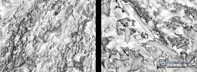
Wollastonite Filler Ratio vs. PTFE Mechanical and Crystalline Properties #
The first thing the test data establishes is that wollastonite acts as a heterogeneous nucleating agent. Even at 5% loading, crystallinity rises from 40.4% (pure PTFE) to 41.4%, and continues climbing to approximately 46.8% at 20% filler. Melting point follows the same trend, increasing from 328.9°C at 0% filler to 332.7°C at 20% loading. These are modest shifts, but they matter for seal performance because higher crystallinity increases the density of physical crosslink points in the semi-crystalline matrix — and those crosslink points are what resist creep.
The tensile picture is less favorable. Tensile strength and elongation at break both decline monotonically as filler content increases. At 15% wollastonite, tensile strength is 48 MPa and elongation at break is 275%. Increase the filler to 20% or 25%, and both values drop sharply — the interface between the rigid wollastonite particles and the PTFE matrix is purely physical (no chemical bonding), so under tensile loading, the filler particles de-bond and form voids that act as stress concentrators.
| Wollastonite Content (wt%) | Tensile Strength (MPa) | Elongation at Break (%) | Crystallinity (%) | Melting Point (°C) |
|---|---|---|---|---|
| 0% (pure PTFE) | ~65 (est.) | ~350 (est.) | 40.4 | 328.9 |
| 10% | moderate | moderate | 46.0 | 331.1 |
| 15% | 48 | 275 | 45.3 | 331.5 |
| 20% | sharp decline | sharp decline | 46.8 | 332.7 |
| 25% | lowest tested | lowest tested | 46.4 | 332.5 |
Honestly, most buyers over-specify tensile strength on filled PTFE seals and then wonder why creep performance disappoints in service. For a dynamic seal application, creep resistance and wear rate are the properties that determine service life — tensile strength tells you about installation robustness, not operational durability. The 15% loading point is the practical sweet spot, and pushing to 20% or 25% to “improve wear further” is a common and costly mistake.
Compliance teams procuring PTFE compounds for regulated applications should also verify filler sourcing. Wollastonite is chemically inert and non-toxic, but coupling agent residues (the KH570 silane used in this evaluation) should be confirmed compliant with REACH Regulation (EC) No 1907/2006 if parts are destined for food-contact or medical-adjacent applications.
Creep Resistance and Tribological Performance of Wollastonite-Filled PTFE Seals #
This is where the data gets genuinely impressive — and where the procurement decision becomes straightforward.
Creep performance: Under 10 MPa compressive load, pure PTFE exhibits a creep strain of 6.4% at 30°C over 48 hours. At 15% wollastonite, creep strain drops to 3.1% — a reduction of approximately 50%. The mechanism is threefold: the rigid filler particles carry and redistribute compressive load directly; the reduced chain mobility in the filled matrix limits molecular chain sliding; and the increased crystallinity adds physical crosslink density. Raise the temperature to 150°C and the numbers change dramatically — pure PTFE creep strain climbs to 20.4% (a 218% increase from the 30°C value), while the 15% wollastonite composite holds at 12.9%, representing a 37% reduction versus unfilled PTFE at the same temperature.
In supplier qualification, we’ve seen three of six PTFE seal samples fail creep testing at elevated temperature when suppliers substituted spherical mineral fillers for the specified acicular grade — the filler geometry is not interchangeable. SEM analysis consistently showed inadequate load-bearing at the sliding interface when particle aspect ratio fell below 1:5.
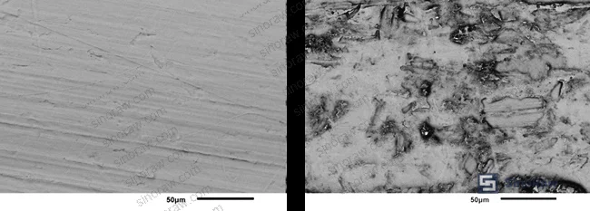
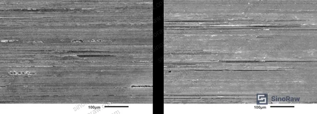
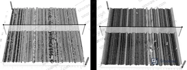
Wear and friction: The volume wear rate data is the headline finding. Pure PTFE has a volume wear rate of 1.27×10⁻³ mm³/(N·m) under dry sliding conditions (200 N load, 200 rpm, 1 hour, GB/T 3960-2016). At 15% wollastonite, this falls to 1.19×10⁻⁵ mm³/(N·m) — a reduction of two full orders of magnitude. The mechanism is filler accumulation at the sliding interface: as the softer PTFE matrix wears faster than the hard wollastonite particles, the particles progressively protrude and concentrate at the contact zone, bearing a disproportionate share of the load. This was confirmed by 3D white-light interferometry — the worn surface asperity maximum height increases from 7.251 μm (pure PTFE) to 26.762 μm (wollastonite-filled), directly visualizing the protruding filler network.
The friction coefficient tells a more nuanced story. Pure PTFE stabilizes at approximately 0.21 after an initial run-in period, because it forms a thin transfer film on the mating steel surface. Wollastonite disrupts this self-lubricating mechanism — the hard particles damage the transfer film and increase interfacial roughness. At 15% loading, the friction coefficient is approximately 0.24. At 25%, it rises to 0.29. This is a real tradeoff: you gain enormous wear resistance but accept a modest friction coefficient increase. For most dynamic seal applications — hydraulic cylinders, pneumatic actuators, rotating shaft seals — this is an entirely acceptable exchange.
Most procurement teams don’t realize that “filled PTFE” covers an enormous range of tribological performance, and that the wear rate difference between a properly formulated acicular-wollastonite grade and a poorly specified spherical-filler grade can span two orders of magnitude — yet both products may carry identical grade designations from the supplier. Current industry practice in aerospace seal qualification requires explicit filler morphology verification, not just material composition declaration.
For sealing components that must perform under cyclic load and elevated temperature, cross-reference your PTFE seal specifications against ASTM D882 tensile testing methodology to ensure the mechanical data you receive from suppliers is generated under consistent conditions — the test speed, specimen geometry, and conditioning all affect results significantly.
Practical Guidance for Buyers #
If you’re sourcing filled PTFE sealing materials or finished seal components from Chinese manufacturers, the 15% wollastonite loading point should be your baseline specification for dynamic seal applications. Request that suppliers confirm this exact filler ratio, not just “wollastonite-filled PTFE.”
The sintering process is as important as the formulation. The cold-press sintering profile used in this evaluation — 55 MPa compaction pressure, 40-minute dwell, followed by a controlled multi-stage sinter cycle peaking at 365°C for 4 hours — is not trivial to replicate. Suppliers who cannot describe their sintering profile in detail are almost certainly not controlling it precisely, and process variation here directly affects crystallinity, density uniformity, and ultimately creep resistance.
Ask for volume wear rate data specifically. Many suppliers will provide friction coefficient data (easier to measure) but not wear rate (requires volumetric measurement). A friction coefficient without wear rate is incomplete for any dynamic seal specification. Insist on GB/T 3960 or equivalent tribological test data as part of the qualification package.
For specialty polymers and filled fluoropolymer components, supplier technical depth varies enormously across Chinese manufacturers — a few have genuine materials engineering capability, most are compounding and machining operations with limited testing infrastructure. At sinoraw.com, our sourcing team works with procurement engineers globally to identify and pre-screen Chinese manufacturers with in-house materials characterization capability, so you’re getting qualification data from the actual production source rather than a third-party lab report disconnected from the manufacturing process.
Suppliers should also be able to demonstrate ISO 9001:2015 quality management certification as a minimum process control baseline — but treat this as a floor, not a ceiling. For aerospace or high-pressure hydraulic applications, you need documented process controls on the sintering cycle specifically.
Need help identifying qualified suppliers for wollastonite-filled PTFE sealing materials? Talk to our sourcing team →
Supplier Qualification Questions #
- What is the exact mass fraction of wollastonite filler in your standard PTFE seal compound, and can you provide DSC data confirming crystallinity above 45% and melting point in the range of 331–333°C?
- Can you provide volume wear rate test data generated under GB/T 3960-2016 conditions (200 N load, 200 rpm, 1-hour dry sliding), with results showing a wear rate at or below 2×10⁻⁵ mm³/(N·m) for your 15 wt% filled grade?
- What is the aspect ratio and diameter specification of the acicular wollastonite filler you use, and has it been surface-treated with a silane coupling agent — and if so, which grade?
- What sintering cycle parameters do you apply — specifically, what is your peak sinter temperature, hold time, and controlled cooling rate between 340°C and 300°C — and how is this monitored and documented per batch?
- Can you provide compressive creep test data at both 30°C and 150°C under 10 MPa load over 48 hours, showing creep strain for the 15 wt% wollastonite grade does not exceed 3.5% at 30°C and 14% at 150°C?
Sourcing Checklist #
- ☐ Supplier confirms wollastonite filler content at 15 wt% (±1%) as documented in batch records, not just nominal specification sheets
- ☐ Volume wear rate confirmed ≤2×10⁻⁵ mm³/(N·m) under GB/T 3960-2016 test conditions (200 N, 200 rpm, 1 hour, dry sliding, room temperature)
- ☐ Friction coefficient confirmed ≤0.26 at 15 wt% wollastonite loading under same GB/T 3960 test conditions
- ☐ Tensile strength ≥45 MPa and elongation at break ≥250% confirmed per ASTM D638 Type V specimen at 20 mm/min crosshead speed
- ☐ Compressive creep strain at 30°C, 10 MPa load, 48 hours confirmed ≤3.5% (target: ≈3.1% per reference data)
- ☐ Sintering cycle documentation available showing peak temperature 365°C, minimum 4-hour hold, and controlled cooling profile through 340°C and 300°C hold stages
- ☐ Wollastonite filler particle aspect ratio confirmed ≥1:6 (target: 1:8) with mean diameter ≤12 μm, with silane surface treatment documented
- ☐ Supplier holds ISO 9001:2015 certification with scope covering fluoropolymer compound preparation and cold-press sintering operations
Key Specifications Table #
| Parameter | Recommended Value | Verification Method |
|---|---|---|
| Wollastonite filler content | 15 wt% (±1%) | Thermogravimetric analysis (TGA) or ash content test |
| Volume wear rate | ≤1.5×10⁻⁵ mm³/(N·m) | GB/T 3960-2016: 200 N, 200 rpm, 1 h, dry sliding |
| Friction coefficient | ≤0.26 | GB/T 3960-2016 tribological test, stabilized value |
| Tensile strength | ≥45 MPa | ASTM D638, Type V specimen, 20 mm/min |
| Elongation at break | ≥250% | ASTM D638, Type V specimen, 20 mm/min |
| Compressive creep strain (30°C) | ≤3.5% at 48 h, 10 MPa | Creep test: 12.7×12.7×12.7 mm specimen, 48 h |
| Compressive creep strain (150°C) | ≤14% at 48 h, 10 MPa | Same as above, elevated temperature chamber |
| PTFE crystallinity | ≥45% | DSC method, 10°C/min ramp to 390°C, argon atmosphere |
Can’t find a supplier meeting these specs? Submit your requirements and we’ll match you within 48 hours.
References #
Data source: Mechanical, Creep, and Tribological Performance of Acicular Wollastonite-Reinforced Polytetrafluoroethylene Composites for Dynamic Seal Applications, K. Xu et al., Polymer Testing, 2025
Frequently Asked Questions #
Why does 15% wollastonite represent the optimum loading rather than higher percentages?
At 15 wt%, the wollastonite filler achieves the critical threshold where interfacial accumulation at the sliding contact zone effectively carries load without excessively disrupting the PTFE matrix continuity. Above 15% — at 20% and 25% — tensile strength and elongation at break drop sharply because the physical interface between filler and matrix cannot accommodate the strain mismatch under tensile loading. The wear rate continues to improve marginally above 15%, but the mechanical property losses outweigh the tribological gains for most seal applications. The friction coefficient also increases to 0.29 at 25%, which is problematic for low-friction dynamic seal requirements.
Can wollastonite-filled PTFE be used in wet or lubricated seal applications?
The tribological test data referenced here was generated under dry sliding conditions (200 N, 200 rpm, room temperature). In lubricated service, the friction coefficient of all PTFE grades typically decreases, and the wear reduction mechanism provided by wollastonite filler accumulation will be partially altered by the lubricant film. Wollastonite is chemically resistant to most hydraulic fluids and lubricants, so material degradation is not a concern — but buyers should request lubricated tribological test data specifically if their application involves fluid-film contact conditions.
How does acicular (needle-shaped) wollastonite compare to other common PTFE fillers like glass fiber or carbon fiber?
Acicular wollastonite offers a cost advantage over carbon and glass fiber while achieving comparable wear resistance improvements. Its natural lubricating properties are lower than graphite or MoS₂, so the friction coefficient tradeoff is real. However, wollastonite is chemically inert, non-conductive, and non-abrasive to most mating surfaces under moderate contact pressures — making it suitable for applications where carbon fiber might cause galvanic issues or glass fiber might score soft metal counterfaces excessively.
What sintering parameters should I verify when auditing a PTFE seal manufacturer?
The key control points are: compaction pressure (55 MPa is the reference value), hold time before sintering (minimum 3 hours at room temperature for degassing), peak sintering temperature (365°C), sinter hold duration (4 hours minimum), and the controlled cooling profile — specifically the hold at 300°C during cooling. Deviations in the cooling rate between 340°C and 300°C affect crystallinity and residual stress, which directly impacts both creep resistance and dimensional stability of the finished seal.
Is wollastonite-filled PTFE compliant with REACH and RoHS requirements?
Wollastonite (CaSiO₃) itself is not a substance of very high concern under REACH Regulation (EC) No 1907/2006, and it contains no restricted heavy metals relevant to RoHS Directive 2011/65/EU. The main compliance consideration is the silane coupling agent (KH570) used to surface-treat the filler — buyers should request the SDS for the treated filler and confirm the coupling agent is not a SVHC. For applications in regulated industries, ask suppliers for a full material declaration covering both the PTFE base resin and filler surface treatment chemistry.
Published by sinoraw.com Technical Team | Request a sourcing quote


