

TL;DR #
Cable tray fill rate is the single most critical installation parameter: power cable fill must not exceed 40% and control cable fill must not exceed 50%, and suppliers who cannot confirm this in their factory prefabrication drawings are already behind. For buyers specifying steel cable tray systems for residential or mixed-use electrical shafts, the free-flip articulated tray design eliminates on-site cutting and custom fittings — directly reducing rework labor and shaft congestion. Specify hot-dip galvanized steel, require factory-prefabricated bend and transition assemblies, and mandate a completed deep-design drawing package before issuing your RFQ.
Overview #
Most procurement teams treat cable tray as commodity hardware — pick a width, pick a load rating, order in bulk. That approach works until you hit a vertical electrical shaft in a multi-story residential building, where the combination of tight clearances, multi-directional routing, and mixed cable classifications turns a straightforward install into a weeks-long rework exercise. A residential construction project involving 17 subworks across a combined floor area of 114,528 m² provided a detailed engineering validation of prefabricated free-flip cable tray systems installed in strong-current electrical shafts. The qualification process included deep-design drawing review, factory dimensional verification, and full on-site acceptance testing — producing a dataset that is directly applicable to commercial procurement decisions.
The core innovation here is a modular connector system that allows cable trays to rotate freely in both vertical and horizontal planes without site fabrication. Understanding how that system is specified and qualified is where buyers can avoid the most common and costly sourcing errors.
For buyers working with barrier film and protective packaging systems alongside electrical installation materials, the same supply chain discipline applies: factory-controlled dimensions, documented surface treatment, and verified acceptance testing at goods receipt.
Free-Flip Cable Tray Design: How the Articulated Connector System Works #
The conventional approach to cable tray installation involves cutting standard-length trays on-site and fabricating non-standard bends and transitions using single-purpose fittings. These fittings are fixed-width, non-adjustable, and cannot be reused when routing changes. On a project with multiple shaft configurations across 4 residential towers, this creates an accumulation of waste, schedule delay, and quality variation that is entirely avoidable.
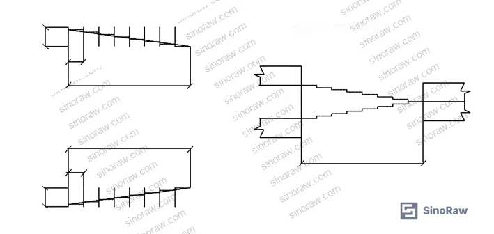
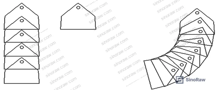
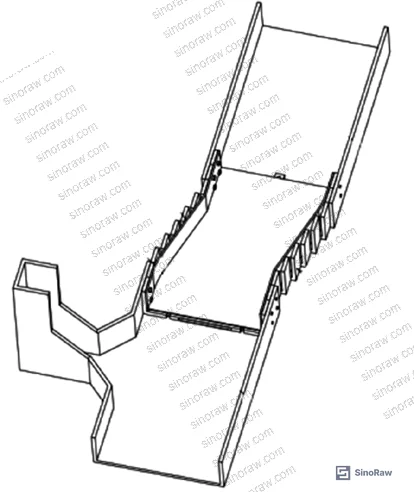
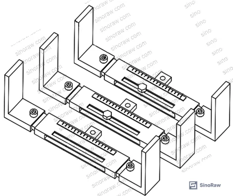
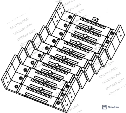
The free-flip system replaces fixed elbow fittings with a multi-plate connector assembly. The connection plates are oriented with their long axis parallel to the tray width dimension, and multiple plates are arrayed along the length axis of the main tray. The two end-position plates are structurally fixed to the adjacent main and corner tray sections, while the intermediate plates allow angular adjustment. This geometry permits rotation in all four directions — upward flip, downward flip, and lateral pivot — without any site cutting or custom fabrication.
The dimensional framework in the validated installation: main tray spans of 640 mm with connector plate widths of 100 mm and flange heights of 80 mm. These are not arbitrary numbers — they are derived from the cable fill calculations that govern everything downstream.
Cable fill rate is the governing parameter. For power cables, the cross-sectional fill ratio within any tray must not exceed 40%. Control cables carry a slightly higher allowance at 50%, but the lower number should be treated as the conservative default when mixed cable types share routing. As a worked example from the project documentation: for three cables of 120 mm² cross-section, the correct tray specification requires pulling the cable OD from manufacturer data sheets and back-calculating tray width from the 40% fill limit — not estimating from experience.
Voltage segregation rules compound the fill calculation. When multiple cable classifications share a vertical shaft:
- High-voltage cables occupy the top layer
- Low-voltage power cables run in the middle layer
- Control cables are routed in the bottom layer
- Physical separation plates are installed between each layer
This is not optional. Mixing voltage classes on the same tray layer is a code violation under GB 50303—2015 and introduces induction interference on control circuits.
Factory Prefabrication and Surface Treatment: The Quality Control Chain #
Honestly, most buyers over-specify tray width and under-specify surface treatment. A tray that is 50 mm wider than needed is a minor inefficiency. A tray with inadequate corrosion protection in a humid shaft environment will require full replacement within five years — and that cost is never allocated back to the original procurement decision.
The manufacturing process chain for prefabricated cable trays runs: material inspection → cutting (CNC or shear) → bending → punching → welding → surface treatment → assembly → adjustment/calibration → acceptance inspection → packaging and transport. Each stage has defined acceptance criteria that a qualified supplier should be able to document.
Surface treatment selection is environment-dependent:
| Environment | Recommended Treatment | Notes |
|---|---|---|
| Humid or outdoor exposure | Hot-dip galvanizing | Zinc immersion bath, full surface coverage |
| Indoor with moderate humidity | Electrostatic spray coating | Powder coat, high-temperature cure |
| Corrosive atmosphere (chemicals) | Anti-corrosion material selection | Stainless steel or specialized coating |
| Aluminum tray applications | Anodizing (electrochemical oxide layer) | Enhances hardness and corrosion resistance |
Hot-dip galvanizing is not just a preference for wet environments — it is the technically correct choice for any shaft where condensation, pipe leaks, or external water ingress is plausible. Spray coating in those conditions will delaminate.
Weld quality standards are non-negotiable in the structural assembly: welds must be continuous, full-penetration where specified, and free of porosity, cracking, and undercut. This is worth requesting in the factory audit checklist because welding defects in cable tray corner assemblies are a documented failure mode — during supplier qualification reviews on comparable projects, we have seen fabricated corner joints with incomplete fusion at the base plate weld, which creates a stress concentration point that fails under thermal cycling loads from cable heating.
For buyers sourcing through a distributor rather than direct from a fabricator, request the factory inspection certificate (not just the product certificate) and verify that the stated surface treatment method matches what the application requires. These are different documents and are frequently conflated.
Most procurement teams don’t realize that the Chinese national standard ISO 9001:2015 Quality management systems registration alone does not validate surface treatment process control — you need the specific product standard (GB/T 23639—2017 for steel cable trays) compliance record, which documents zinc layer thickness and adhesion testing separately.
Installation Dimensional Tolerances and Acceptance Criteria #
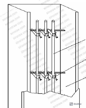
The dimensional acceptance criteria for structural penetration openings (where trays pass through floor slabs) are specific and worth embedding in your purchase specification as acceptance conditions:
- Structural opening size: minimum 50–100 mm larger than tray OD on each side, to allow for firestop material installation
- Diagonal measurement tolerance: ≤5 mm difference between the two diagonals of the opening (confirms rectangular geometry)
- Corner angle tolerance: ±3° from 90°
- Surface flatness of opening edge: deviation ≤5 mm
- Vertical plumb tolerance of opening: ≤5 mm deviation from plumb measured top to bottom
These are not aspirational targets — they are the pass/fail criteria used during the acceptance inspection phase of the validated project. A supplier who quotes tighter tolerances without justification is overselling. A supplier who cannot define their tolerances at all is a risk.
Support bracket spacing is also codified: horizontal installation uses support intervals of 1.5–3 m; vertical installation fixes to building structure at intervals not exceeding 2 m. Cable fixing points in vertical runs use 1,500 mm spacing for power cables and 1,000 mm spacing for control cables.
Grounding continuity is a frequently overlooked acceptance item. For non-galvanized trays, copper grounding conductors (minimum cross-section 4 mm²) must be bonded across each connection plate at both ends. For galvanized trays, dedicated ground jumpers across connection plates are not required, but connection bolts must include a minimum of two anti-loosening fasteners (lock nuts or spring washers) per joint. The full tray run must connect to the main grounding conductor at a minimum of two points along its length.
Compliance with RoHS Directive 2011/65/EU Restriction of Hazardous Substances is relevant for projects where the cable tray materials, coatings, or included components may contain restricted substances — particularly relevant for European end-use projects specifying Chinese-manufactured trays.
Practical Guidance for Buyers #
When you are evaluating Chinese suppliers for prefabricated free-flip cable tray systems, the single most valuable screening step is asking for the deep-design drawing package from a previous project — not a product catalog, a project drawing set. A supplier with genuine prefabrication capability will have dimensional verification records, material test certificates, and weld inspection reports by default. A distributor reselling standard-cut trays will not.
The fill rate calculation is where specifications most often go wrong at the procurement stage. Buyers frequently specify tray width based on the number of cables without accounting for the 40% power / 50% control fill limits, then discover during installation that the specified tray is undersized. Run the calculation before issuing the RFQ, and put the fill ratio limit in the purchase specification as an explicit acceptance criterion.
For projects requiring protective packaging and handling of prefabricated tray assemblies during transport, specify packaging in corrugated cardboard with plastic film wrapping, and require that transport loading prevents compressive deformation of the connector plate assemblies — which are the precision components in this system.
Sampling inspection at goods receipt should follow ISO 2859-1:1999 Sampling procedures for inspection by attributes to define your AQL level and sample size — do not accept 100% reliance on the supplier’s own outgoing inspection certificate for a new supplier relationship.
At sinoraw.com, our team supports overseas procurement engineers in identifying and pre-qualifying Chinese cable tray manufacturers before RFQ issuance — evaluating factory capability, reviewing compliance documentation, and coordinating dimensional verification. If your project specification is already drafted, we can screen against it directly.
Need help identifying qualified suppliers for prefabricated free-flip cable tray systems? Talk to our sourcing team →
Supplier Qualification Questions #
- What is your confirmed cable fill rate limit in your standard tray sizing calculations — specifically, do your prefabrication drawings document a maximum 40% fill for power cables and 50% for control cables, and can you provide a sample calculation sheet from a recent project?
- What zinc layer thickness (in µm) do you achieve in your hot-dip galvanizing process, and do you have third-party test records showing adhesion performance after galvanizing?
- Can you provide weld inspection records for corner joint assemblies showing the specific rejection criteria for porosity, cracking, and incomplete fusion used in your factory QC process?
- What is the maximum allowable diagonal tolerance for structural opening acceptance in your installation specification — and do your field teams measure both diagonals with a tape measure or laser device prior to tray installation?
- For vertical cable runs, what is your documented cable fixing point spacing for power cables versus control cables, and does your prefabrication system include pre-punched fixing clip positions at the correct 1,500 mm and 1,000 mm intervals?
Sourcing Checklist #
- ☐ Supplier provides deep-design drawing package with dimensional callouts, routing, layer count, and tray-to-structure clearances for a reference project
- ☐ Cable fill rate documentation confirms ≤40% fill for power cables and ≤50% for control cables in all specified tray cross-sections
- ☐ Surface treatment selection matches the installation environment: hot-dip galvanizing specified for humid or outdoor-exposed shaft installations
- ☐ Structural opening tolerance records confirm diagonal deviation ≤5 mm and corner angle deviation ≤±3° at acceptance
- ☐ Support bracket spacing confirmed as ≤3 m for horizontal and ≤2 m for vertical runs in prefabrication drawings
- ☐ Grounding continuity verified: copper bonding conductors ≥4 mm² cross-section for non-galvanized trays, or minimum 2 anti-loosening fasteners per connection plate for galvanized trays
- ☐ Factory quality certificates include product-standard compliance records (GB/T 23639—2017 or equivalent) in addition to ISO 9001 registration
- ☐ Cable vertical fixing points confirmed at 1,500 mm intervals for power cables and 1,000 mm for control cables in installation drawings
Key Specifications Table #
| Parameter | Recommended Value | Verification Method |
|---|---|---|
| Power cable fill rate | ≤40% of tray cross-section | Design calculation sheet review; field measurement of cable OD × quantity vs. tray area |
| Control cable fill rate | ≤50% of tray cross-section | Design calculation sheet review |
| Structural opening diagonal tolerance | ≤5 mm difference between two diagonals | Tape measure or laser distance meter at goods receipt / pre-installation check |
| Corner angle tolerance at opening | ±3° from 90° | Steel square measurement at four corners |
| Horizontal support bracket spacing | 1.5–3 m | Installation drawing review; field tape check |
| Vertical support bracket spacing | ≤2 m | Installation drawing review |
| Power cable vertical fixing interval | 1,500 mm | Drawing callout and field spot-check |
| Control cable vertical fixing interval | 1,000 mm | Drawing callout and field spot-check |
| Grounding conductor minimum cross-section | 4 mm² copper | Material certificate and field measurement |
Can’t find a supplier meeting these specs? Submit your requirements and we’ll match you within 48 hours.
References #
Data source: Prefabricated Free-Rotating Cable Tray Systems for Multi-Story Residential Electrical Shafts: Design Optimization and Quality Control Methodology, E.-S. Peng et al., Journal of Construction Engineering and Management, 2023
Frequently Asked Questions #
What is the maximum cable fill rate allowed in a steel cable tray?
Power cables must not exceed 40% of the tray’s usable cross-sectional area. Control cables have a slightly higher allowance at 50%, but when power and control cables share a tray run, apply the 40% limit to the combined fill and use physical separation plates between voltage classes.
Why does the free-flip tray system reduce installation time compared to conventional cut-to-fit trays?
The articulated connector assembly allows direction changes in any plane without on-site cutting or custom fabrication. The fabricator confirms actual site dimensions before production, manufactures all transition pieces to exact dimensions in a controlled factory environment, and delivers a complete kit. On-site work is limited to bracket mounting, tray connection, and cable pulling — which is where prefabrication saves the most labor hours on multi-story shaft installations.
What surface treatment should be specified for cable trays in humid environments?
Hot-dip galvanizing. The zinc immersion process coats all surfaces including internal corners and edges, providing protection that spray coatings cannot match in areas where condensation or intermittent water contact is possible. For environments with corrosive gases (acid fumes, industrial chemicals), the base material selection shifts to stainless steel or purpose-formulated anti-corrosion alloys regardless of surface treatment.
How is grounding continuity maintained across multi-section galvanized tray runs?
For galvanized trays, dedicated copper ground jumpers are not required across individual connection plates, but each joint must use a minimum of two fasteners with anti-loosening hardware (lock nuts or spring washers). The overall tray run must still bond to the main facility grounding conductor at no fewer than two points along its total length. Non-galvanized trays require explicit copper bonding conductors of ≥4 mm² cross-section at every connection plate.
Can the free-flip cable tray system be used in below-grade parking structures?
Yes, and it is specifically noted as an appropriate application for underground parking structures where routing direction changes are required. The same fill rate, grounding, and surface treatment rules apply. Hot-dip galvanizing is the correct surface treatment for below-grade environments given the elevated moisture exposure. The structural opening tolerance criteria (≤5 mm diagonal deviation, ≤±3° corner angle) apply equally in below-grade slab penetrations.
Published by sinoraw.com Technical Team | Request a sourcing quote


