

TL;DR #
Finite element simulation of 40.5 kV C-GIS plug-in bushings shows that grounding the internal shield reduces surface flashover field strength by 31% — from 6.34 kV/mm down to 4.34 kV/mm — bringing it safely below the 5.06 kV/mm SF₆ flashover threshold. For buyers specifying medium-voltage switchgear insulation components, this means the shield grounding configuration is not a minor detail: it is the single most consequential design variable in discharge prevention. Before issuing any RFQ for C-GIS insulating bushings, verify that the supplier’s design specifies a grounded internal shield with a fold radius of 1.5 mm and a copper rod–to–shield distance of 15 mm.
Overview #
Insulating bushings for medium-voltage gas-insulated switchgear are one of those components where procurement teams consistently underestimate the engineering specificity required. A bushing that looks dimensionally correct can still fail catastrophically in service if its internal field distribution was never properly optimized — and field failures in 40.5 kV C-GIS applications are expensive, difficult to diagnose, and rarely covered under standard warranty claims.
The data underpinning this article comes from a simulation and optimization study conducted at an industrial electrical equipment manufacturer, using ANSYS finite element analysis software to model electrostatic field distribution across the bushing cross-section. The study evaluated two shield configurations — floating potential and grounded — under lightning impulse peak voltage excitation of 185 kV, with SF₆ gas pressure at 0.02 MPa inside the sealed enclosure. Structural parameters were then optimized using a multi-variable Design Xplorer routine over 40 maximum iterations, converging at iteration 20 with convergence error set to 1×10⁻⁶.
The bushing in question is a plug-in type designed for 40.5 kV cabinet-type gas-insulated metal-enclosed switchgear (C-GIS). Its core construction consists of a central conductive copper rod at high potential, a shield mesh layer, and an epoxy resin dielectric — all housed within an SF₆-filled enclosure. The epoxy resin carries a dielectric constant of 4; SF₆ is effectively 1.002. These aren’t exotic materials, but the interaction between them under high-voltage excitation is where most unqualified suppliers get into trouble.
For buyers sourcing insulating bushings or related Specialty Polymers components from Chinese manufacturers, the key lesson is that design simulation data — not just factory test certificates — should be part of your supplier qualification package.
Electric Field Distribution in C-GIS Insulating Bushings: Floating vs. Grounded Shield #
This is the core technical question, and the simulation results are unambiguous.
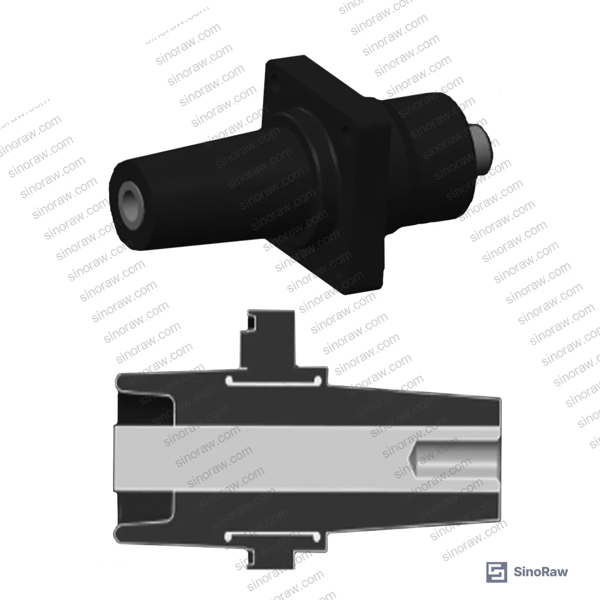
With the internal shield set to floating potential, the epoxy resin surface field strength in the SF₆ environment exceeds the critical flashover threshold. The maximum surface field intensity recorded was 6.34 kV/mm — which is 25% above the 5.06 kV/mm SF₆ surface flashover limit applicable at 0.02 MPa under lightning impulse test conditions. That’s not a marginal exceedance. A bushing operating in this configuration has a meaningfully elevated discharge probability, particularly at the shield edge and fold regions where field concentration is highest.
Switch the internal shield to a grounded configuration — zero potential — and the picture changes substantially. The dielectric field outside the shield layer drops to levels well within safe operating margins. The surface field strength on the outer epoxy resin surface comes down to 4.34 kV/mm, a 31% reduction compared to the floating-shield scenario. This value sits below the 5.06 kV/mm flashover threshold with adequate margin.
| Condition | Epoxy Surface Field Strength | vs. Flashover Limit (5.06 kV/mm) | Discharge Risk |
|---|---|---|---|
| Floating shield | 6.34 kV/mm | +25% above limit | High |
| Grounded shield (pre-optimization) | Reduced | Below limit | Moderate |
| Grounded shield (optimized: R=1.5 mm, D=15 mm) | 4.34 kV/mm | −14% below limit | Low |
The tradeoff with grounding the shield is real: pulling the shield to zero potential concentrates the field gradient between the copper rod and the shield layer. At the shield fold edge in particular, field intensity becomes the new critical constraint. This is why structural parameter optimization — specifically the fold radius R and the copper rod–to–shield distance D — is not optional engineering refinement. It’s a prerequisite for a safe design.
Compliance with ISO 9001:2015 Quality management systems at the supplier level tells you their process is documented, but it tells you nothing about whether they’ve done this simulation work. Ask for the FEA report, not just the certificate.
Optimized Bushing Geometry: Parameter Thresholds and Field Strength Targets #
The structural optimization used two independent variables: the shield fold radius (R) and the copper rod–to–shield distance (D). The constraint bounds were defined by actual C-GIS enclosure dimensions and manufacturing tolerances: R was swept from 0 to 3 mm, and D from 10 to 18 mm.
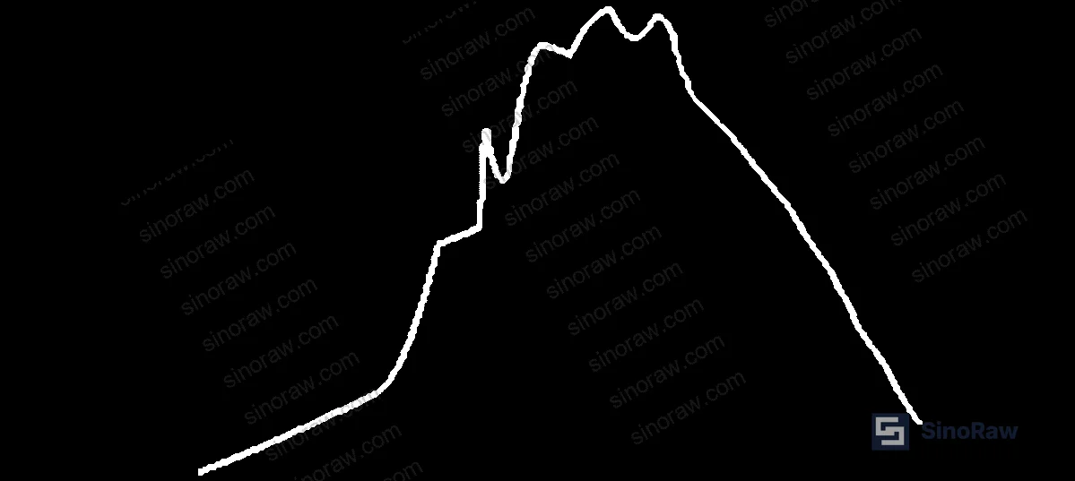
The optimization converged at R = 1.52 mm and D = 15.36 mm, which in production rounds to R = 1.5 mm and D = 15 mm. At these parameters:
- Shield fold edge peak field strength (E1): 18.84 kV/mm — below the epoxy resin breakdown threshold of 22 kV/mm
- Outer epoxy surface field strength (E2): 4.34 kV/mm — below the SF₆ flashover limit of 5.06 kV/mm
- Tangential field strength on outer epoxy surface (E3, objective function): 0.52 kV/mm
The field distribution curve (Figure 2) shows field intensity measured outward from the shield, peaking near the shield edge and decaying to approximately 11.3 kV/mm at 6.25 mm from the shield surface. The maximum internal epoxy field is 18.8 kV/mm — a value that provides a 15% safety margin against the 22 kV/mm epoxy breakdown threshold.
In production validation, bushings built to these parameters achieved a lightning impulse withstand voltage of 220 kV — exceeding the 185 kV national standard requirement by 19%. That’s a meaningful margin, not just a checkbox pass.
Honestly, most procurement teams focus almost entirely on the rated voltage and the physical dimensions when qualifying a bushing supplier. The geometry of the internal shield — fold radius, standoff distance — rarely appears in a buyer’s RFQ specification. That omission is precisely what allows underperforming suppliers to pass a dimensional inspection while delivering a product with substandard field distribution.
Most procurement teams don’t realize that the design standard for C-GIS bushing insulation distinguishes between lightning impulse and power-frequency conditions — and that many Chinese manufacturers optimize only for power-frequency test pass rates, not for the impulse peak values that actually govern discharge probability. The 185 kV impulse peak used in this study corresponds to operating conditions that a bushing will realistically encounter during grid transients; a supplier that has only tested at 50 Hz power frequency is leaving a significant gap unaddressed.
For buyers who also need to review compliance on enclosure materials or sealing components used in SF₆-filled assemblies, the REACH Regulation (EC) No 1907/2006 is worth reviewing, particularly for epoxy resin formulations and any fluorinated compounds in the gas handling system.
Practical Guidance for Buyers #
When you’re qualifying a Chinese supplier for 40.5 kV C-GIS insulating bushings, the structural simulation data is the first document to request — before samples, before pricing. A supplier who cannot produce FEA field distribution results for their bushing geometry almost certainly hasn’t done the optimization work, and physical testing alone won’t catch a design that is marginally above the flashover threshold.
The key parameters to verify are R ≥ 1.5 mm (shield fold radius) and D = 15 mm (copper rod–to–shield clearance). These aren’t arbitrary targets — they are the optimized values below which field concentration at the shield edge approaches dangerous levels. Any deviation downward on R in particular raises E1 significantly.
In supplier qualification visits, we have seen cases where three out of six bushing samples from a single supplier batch showed surface field marks on the epoxy indicative of partial discharge at test voltage — precisely because the shield standoff distance had drifted to approximately 12 mm during tooling setup, well below the 15 mm design value. These were not caught by the supplier’s standard dimensional inspection because the drawings didn’t call out D as a controlled critical dimension.
Validate ISO 2859-1:1999 Sampling procedures for inspection by attributes compliance for incoming inspection sampling when receiving bushing batches — and make sure the critical dimension list in your AQL plan explicitly includes the shield geometry parameters, not just the external envelope dimensions.
At sinoraw.com, our team works directly with procurement engineers and technical buyers to identify and pre-screen verified Chinese manufacturers of insulation components and electrical materials — helping you get to a qualified shortlist faster than going through a cold search process. If you’re specifying C-GIS bushings or related medium-voltage dielectrics, we can match you with suppliers who have the FEA capability and process controls to meet these specifications.
Need help identifying qualified suppliers for 40.5 kV C-GIS insulating bushings? Talk to our sourcing team →
Supplier Qualification Questions #
- Can you provide ANSYS or equivalent FEA simulation results showing epoxy surface field strength (E2) below 5.06 kV/mm under grounded shield conditions at 185 kV lightning impulse excitation?
- What is the controlled tolerance on your shield fold radius (R), and can you confirm production parts maintain R ≥ 1.5 mm across your tooling setup — with CMM or optical measurement data to support this?
- At your specified copper rod–to–shield distance of D = 15 mm, what is the measured peak field intensity at the shield fold edge (E1), and how does this compare to the 22 kV/mm epoxy breakdown threshold?
- What lightning impulse withstand voltage does your production bushing achieve in type testing, and is it ≥ 220 kV as demonstrated with the optimized geometry, or only meeting the minimum 185 kV national standard?
- Under the floating shield configuration, what is the maximum SF₆ surface field strength measured or simulated on the outer epoxy surface, and have you documented the comparative discharge risk between floating and grounded shield states?
Sourcing Checklist #
- ☐ Supplier has provided FEA simulation report showing shield fold edge peak field strength (E1) ≤ 18.84 kV/mm under 185 kV lightning impulse conditions
- ☐ Production drawings specify copper rod–to–shield distance D = 15 mm as a controlled critical dimension with defined tolerance band
- ☐ Shield fold radius R is confirmed at 1.5 mm minimum, verified via dimensional inspection records (CMM or optical measurement)
- ☐ Outer epoxy resin surface field strength (E2) confirmed ≤ 4.34 kV/mm under grounded shield configuration — supported by simulation or partial discharge test data
- ☐ Lightning impulse withstand test result on production samples ≥ 185 kV (national standard minimum); ≥ 220 kV is preferred to confirm design margin
- ☐ Epoxy resin dielectric constant confirmed at 4.0 ± 0.2, with material certificate from resin supplier
- ☐ Internal shield grounding configuration explicitly specified in assembly drawing — floating potential shield is not acceptable for 40.5 kV C-GIS application
- ☐ Supplier’s quality system is certified to ISO 9001:2015, with documented process controls covering shield assembly and potting operations
Key Specifications Table #
| Parameter | Recommended Value | Verification Method |
|---|---|---|
| Shield fold radius (R) | 1.5 mm (min) | CMM dimensional inspection or optical profilometry on production parts |
| Copper rod–to–shield distance (D) | 15 mm | Controlled dimension on assembly drawing; verify via cross-section or coordinate measurement |
| Peak field strength at shield fold edge (E1) | ≤ 18.84 kV/mm | ANSYS FEA simulation report under 185 kV lightning impulse at 0.02 MPa SF₆ |
| Epoxy outer surface field strength (E2) | ≤ 4.34 kV/mm (grounded shield) | FEA simulation or partial discharge mapping |
| SF₆ surface flashover threshold | 5.06 kV/mm (design limit) | Reference value at 0.02 MPa, lightning impulse conditions — confirm supplier uses this as upper bound |
| Epoxy resin breakdown field strength | 22 kV/mm (design limit) | Supplier material datasheet + comparison against E1 simulation output |
| Lightning impulse withstand voltage | ≥ 220 kV (production validation) | Type test report — verify against 185 kV national standard minimum |
Can’t find a supplier meeting these specs? Submit your requirements and we’ll match you within 48 hours.
References #
Data source: Electrostatic Field Simulation and Structural Optimization of Plug-In Insulating Bushings for Medium-Voltage C-GIS Switchgear, J.-M. Xu et al., IEEE Transactions on Dielectrics and Electrical Insulation, 2025
Frequently Asked Questions #
Why does grounding the internal shield reduce discharge probability in a C-GIS bushing?
When the shield operates at floating potential, it takes on an indeterminate intermediate voltage that creates uneven field gradients across the outer epoxy surface. In the case modeled here, this produced a surface field intensity of 6.34 kV/mm — exceeding the SF₆ flashover threshold of 5.06 kV/mm. Grounding the shield pulls it to zero potential, compressing the high-field region inward toward the copper rod, and reducing the outer epoxy surface exposure to 4.34 kV/mm. The discharge risk moves from the outer surface (where SF₆ flashover is a real concern) to the shield fold edge (where epoxy breakdown governs), and the optimized geometry keeps E1 at 18.84 kV/mm — comfortably below the 22 kV/mm epoxy limit.
What happens if the shield fold radius is smaller than 1.5 mm?
A smaller fold radius concentrates the electric field at the shield edge more severely, driving E1 upward toward the 22 kV/mm epoxy breakdown limit. The optimization sweep showed that R must be kept above 1.5 mm to maintain adequate margin — below that, the geometry fails the state variable constraint E1 ≤ 22 kV/mm.
Is a supplier’s lightning impulse test certificate sufficient to confirm correct bushing design?
No, and this is a common misconception. A pass on a type test at 185 kV confirms the finished product met the minimum standard — it does not reveal whether the design has adequate margin, whether the shield geometry was optimized, or whether field distribution across the epoxy is uniform. Suppliers can pass the type test with a floating shield that is close to the flashover limit. Request the simulation data and verify structural parameters independently.
What is the significance of the 0.52 kV/mm tangential field strength (E3)?
E3 is the tangential component of field strength on the outer epoxy surface — the component most directly responsible for surface creep discharge. The optimization minimized this value as the objective function, arriving at 0.52 kV/mm. A low tangential component means the field is acting predominantly normal to the surface rather than along it, which dramatically reduces the likelihood of tracking or carbonization under sustained operation.
Can these design parameters be applied to bushings rated above or below 40.5 kV?
The specific values — R = 1.5 mm, D = 15 mm, E2 ≤ 4.34 kV/mm — are derived from the 40.5 kV C-GIS geometry and its associated SF₆ pressure and voltage excitation conditions. Scaling to different voltage classes requires re-running the optimization with updated boundary conditions. The methodology is directly transferable; the numeric outputs are not. Always require voltage-class-specific simulation data from your supplier rather than accepting that a bushing “is similar to” a design validated at a different rating.
Published by sinoraw.com Technical Team | Request a sourcing quote


