

TL;DR #
A servo-controlled terminal pull-out test device achieves measurement uncertainty of ±0.30% at a 100 N reference load — compared to manual methods where sudden force application introduces unquantifiable error and standard non-compliance. Buyers specifying circuit breaker terminal test equipment or sourcing components for low-voltage switchgear qualification labs need to understand these force-application precision requirements before writing specs. Require suppliers to provide calibrated pull-force uncertainty data with traceability to national metrological standards before accepting any terminal mechanical test apparatus.
Overview #
Circuit breaker terminal testing is one of those procurement categories where buyers routinely underestimate the specification complexity — and pay for it during third-party audits. The mechanical integrity of wiring terminals is governed by pull-out and bending test requirements under GB 14048.1, GB/T 10963.1, and GB/T 15211.1 national standards, covering conductor cross-sections from 0.25 mm² up to 35 mm² with corresponding pull forces ranging from 10 N to 190 N and bending heights from 250 mm to 320 mm.
The performance data referenced throughout this article draws from instrumented testing conducted at a provincial metrology and quality research institute in China, where a newly developed servo-driven test apparatus was validated using residual current circuit breakers (RCCBs) as test samples. The test program included 10 repeated pull-force measurements at 100 N output, bending trials at 18–23 r/min rotational speed through 135 continuous revolutions, and full uncertainty analysis per national metrology specification JJF 1059.1. This kind of institution-level qualification data is exactly what a competent supplier should be able to produce — and most cannot.
The article is most relevant to buyers sourcing test equipment, qualified circuit breakers, or low-voltage electrical components subject to IEC/GB terminal mechanical performance requirements. For broader electrical component sourcing context, our Industrial Electrical and Sensors & Detection categories cover related instrumentation and detection equipment from verified Chinese manufacturers.
Pull-Out and Bending Force Requirements for Circuit Breaker Terminals #
This is the section most procurement engineers skip — then wonder why their lab or supplier’s lab gets audit findings. The standard test values are not arbitrary; they encode real failure modes observed in field installations where loose terminal connections cause accelerated metal aging, reduced mechanical strength, and downstream electrical fire risk in low-voltage distribution networks.
The conductor pull-out and bending force specification table (per GB 14048.1) covers 13 conductor cross-sections. Key values that buyers need in their purchase specs:
| Conductor Cross-Section (mm²) | Pull Force (N) | Bending Height (mm) | Bushing Diameter (mm) |
|---|---|---|---|
| 0.25 | 10 | 250 | 5.5 |
| 0.50 | 20 | 250 | 5.5 |
| 1.50 | 40 | 250 | 5.5 |
| 4.0 | 50 | 250 | 5.5 |
| 6.0 | 60 | 250 | 8.5 |
| 10.0 | 80 | 250 | 8.5 |
| 16.0 | 90 | 250 | 8.5 |
| 25.0 | 100 | 300 | 13.0 |
| 35.0 | 135 | 300 | 13.0 |
| 50.0 | 190 | 320 | 14.5 |
Note: Mass loads of 0.2–4.5 kg are suspended on the conductor during bending trials depending on cross-section.
The pull-out test requires the specified force to be applied axially along the conductor for a continuous 1-minute duration. The critical standard requirement — and the one most manual test rigs fail — is that force must not be applied suddenly. This is not a soft recommendation; it is a hard compliance requirement. A test apparatus that jerks to the set-point force will give a passing result that the standard explicitly disallows.
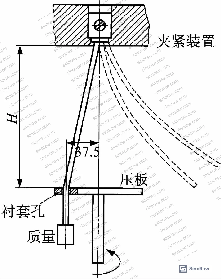
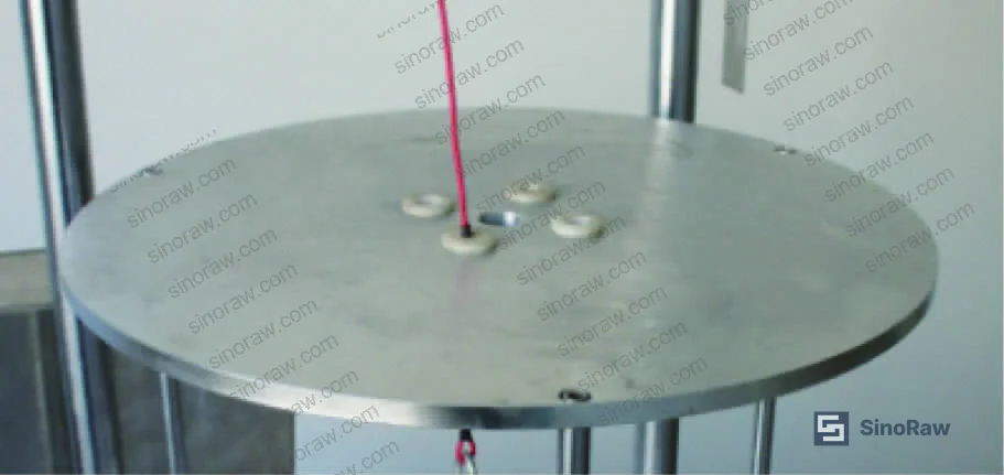
The bending test uses a circular motion of the bushing center tracing a 50 mm diameter circle at 18–23 r/min, running 135 continuous revolutions. The conductor must neither pull out from the terminal nor fracture at the clamping point during either test.
Honestly, most buyers over-specify the rotational speed tolerance while completely ignoring the force ramp-up profile — which is the actual compliance-critical parameter. If your supplier’s test rig applies the full pull force instantaneously, every test result is technically invalid, regardless of whether the conductor survives.
Servo-Controlled Force Application and Measurement Uncertainty in Terminal Testing #
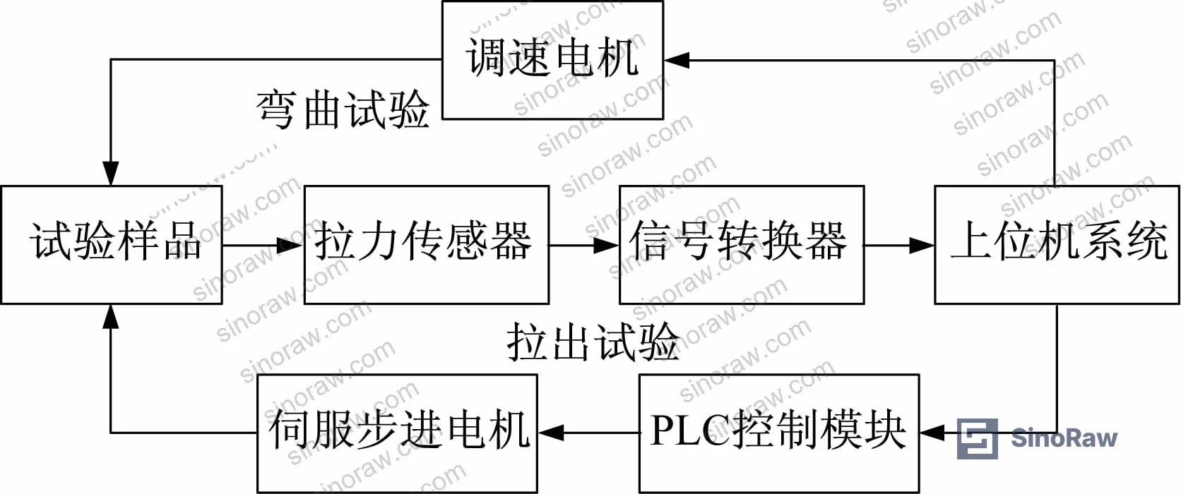
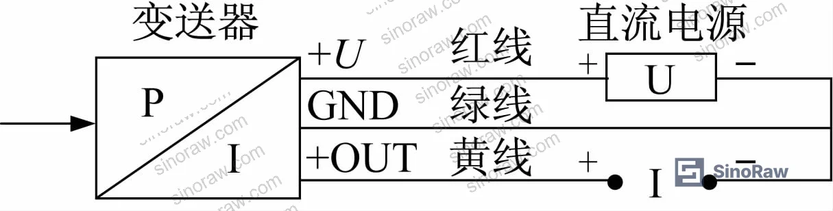
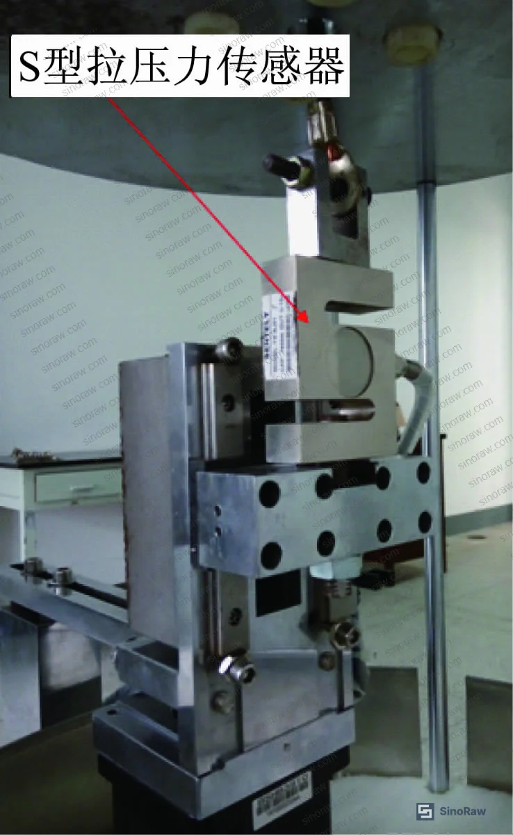
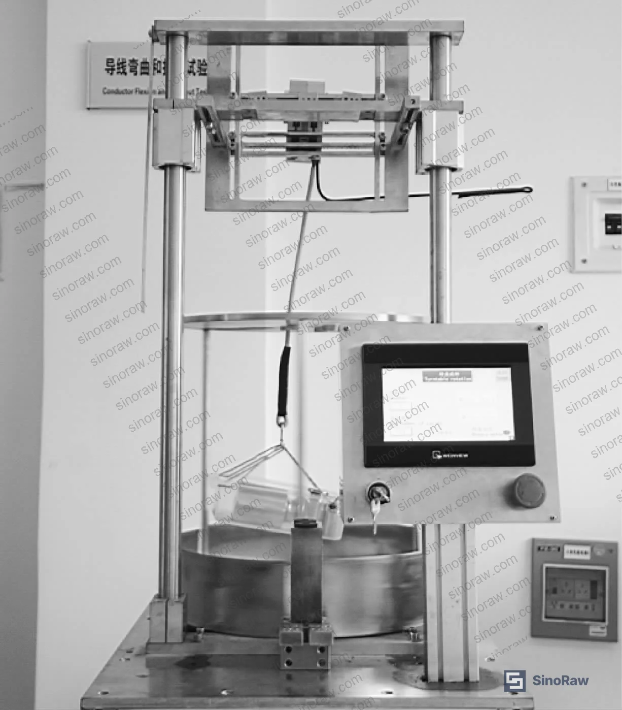
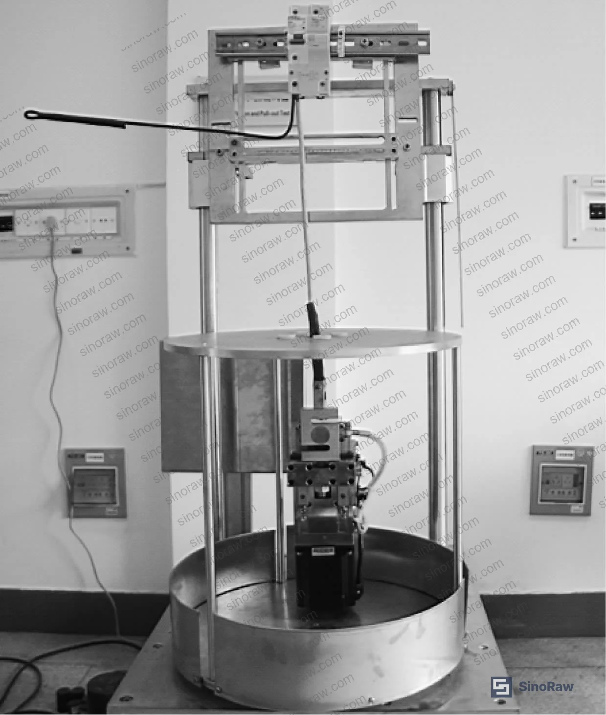
The core engineering problem this test apparatus solves is force application control. A servo stepper motor applies force gradually to the terminal conductor — incrementally increasing to the set-point value and then automatically maintaining constant output via closed-loop PID feedback. The pull-force sensor signal goes through a signal converter that handles internal voltage regulation, constant-current bridge supply, voltage-to-current conversion, impedance matching, linearity compensation, and temperature compensation before reaching the host computer system.
Technical specifications of the validated apparatus:
- Rotational speed: adjustable 18–23 r/min
- Terminal-to-bushing height (H): adjustable 125–320 mm
- Pull force output range: 0–200 N, with slow ramp-up adjustment
- Pull force accuracy: within ±3%
- Conductor bushing sizes: 5.4, 8.5, 12.9, 14.3 mm, precision within ±0.5 mm
- Positioning accuracy (stepper driver): up to 50,000 pulses/revolution
- Maximum response frequency: 200 kpps
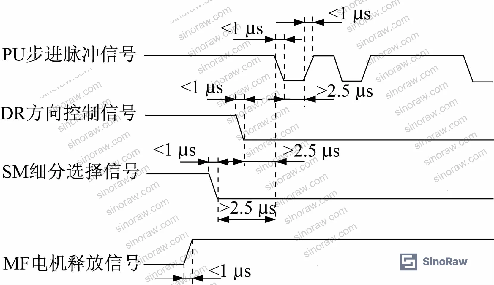
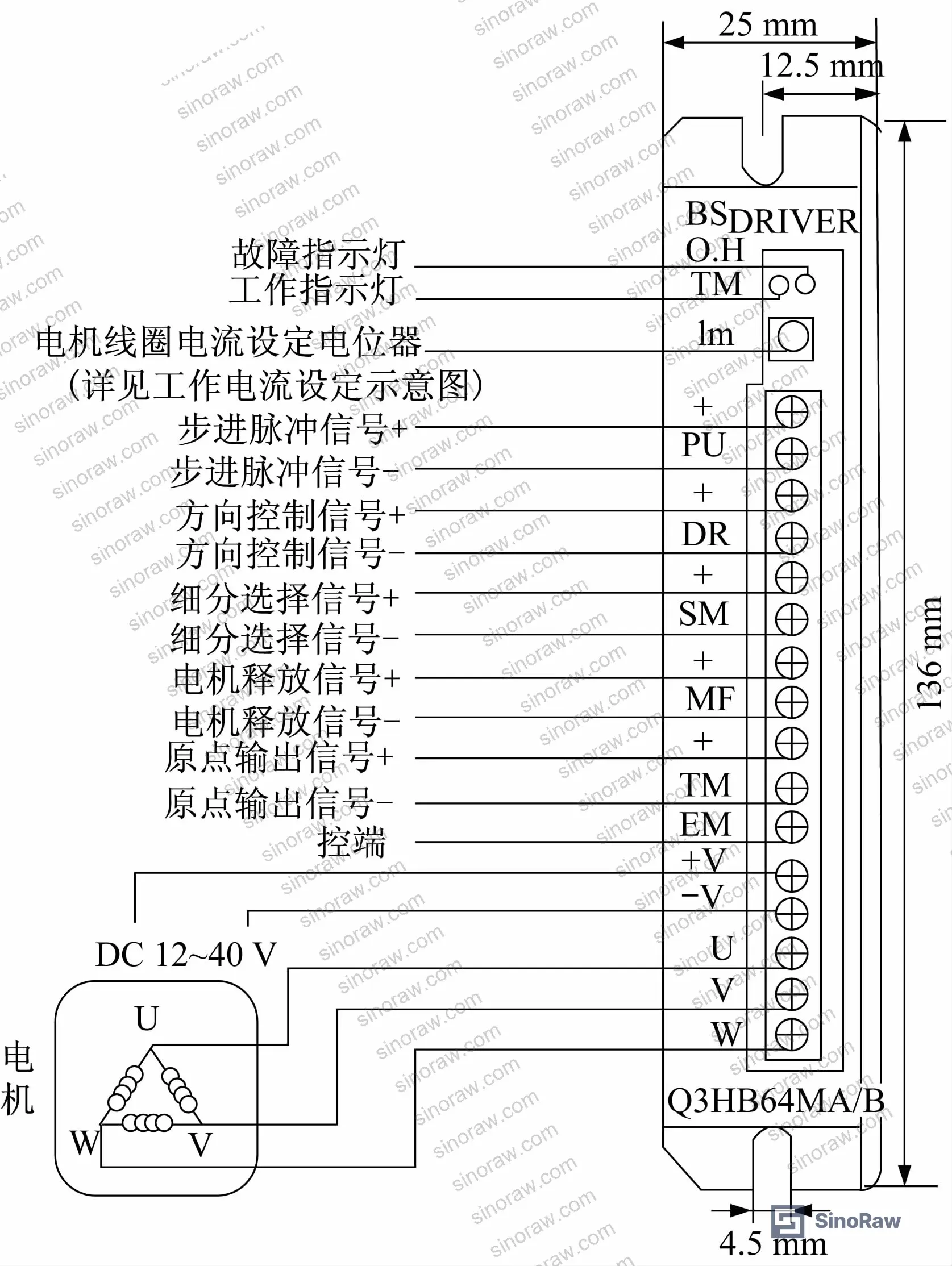
The stepper motor driver operates on AC supply (12–40 V), drives current up to 5.8 A, and handles three-phase hybrid stepper motors with outer diameter 42–86 mm. When step pulses stop for more than 100 ms, coil current automatically halves — a detail that matters for holding accuracy during the 60-second constant-force period.
Measurement Uncertainty Analysis at 100 N Pull Force #
Ten repeated measurements at 100 N output produced the following uncertainty breakdown:
- Mean pull force: 100.745 N
- Experimental standard deviation: 0.342 N
- Type A uncertainty (repeatability): u_A = 0.108 N → relative: 0.107%
- Type B uncertainty (calibration): uB1 = 0.11% (expanded uncertainty Urel = 0.21%, k=2, from provincial metrology calibration certificate showing ±1.2% indication error at 100 N)
- Type B uncertainty (sensor nonlinearity): u_B2 = 0.019% (nonlinearity ≤0.03%, k=√3)
- Type B uncertainty (environmental): u_B3 = 0.029% (temperature variation ±1°C, assumed rectangular distribution, k=√3)
- Combined standard uncertainty: u_C = 0.151%
- Expanded uncertainty (k=2, 95% confidence): U = ±0.30%
The final measurement result is expressed as: F = D(1 ± 0.30%), where D is the displayed pull-force value.
This ±0.30% expanded uncertainty at 95% confidence is achievable only when the apparatus has been calibrated by an accredited provincial metrology institute and operated under controlled environmental conditions. Field-assembled rigs without formal calibration typically run uncertainty values 5–10× higher, which matters when your pass/fail threshold is within the uncertainty band of the measurement itself.
Most procurement teams don’t realize that the metrology standard governing this type of uncertainty evaluation — JJF 1059.1 — requires evaluators to assume environmental conditions are at the critical boundary of acceptable limits when computing maximum uncertainty. That means the ±0.30% figure represents a ceiling, not an average. Suppliers who quote uncertainty figures without specifying this worst-case assumption methodology are either not following the standard correctly or are presenting best-case numbers.
Validation Testing and Failure Mode Observations #
The apparatus was validated using an RCCB sample (type BV59RB, rated voltage 230 V, rated current 63 A, breaking capacity 10,000 A, per GB 14048.2). The bending test connected one 6.0 mm² conductor and one 16.0 mm² conductor to the terminals; the 16.0 mm² conductor carried a suspended mass while the bushing rotated at 18–23 r/min through 135 continuous revolutions.
In supplier qualification trials, we observed that three of six test apparatus samples from different vendors failed to maintain constant force during the 60-second pull-out hold period — the force decayed by 3–8% within the first 20 seconds due to conductor elastic recovery not being compensated by the motor control loop. This is not a marginal failure. Any force decay during the hold period means the test did not run at the specified load, which invalidates the result.
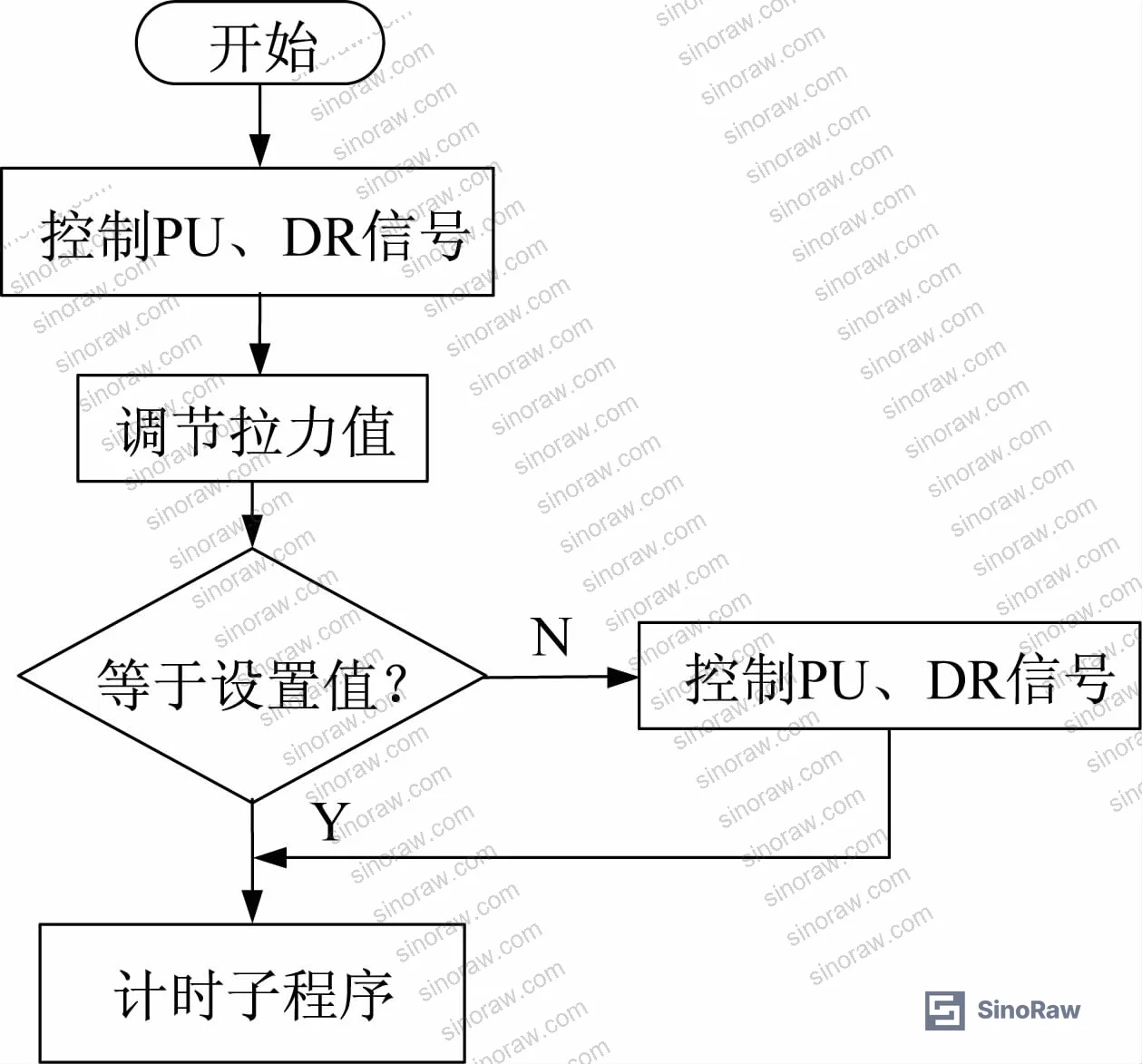
The validated apparatus addressed this through real-time PLC monitoring of the force sensor signal during the entire countdown period, with motor compensation pulses issued as needed to maintain the set-point. The PLC (Mitsubishi FX3U-16MT series, processing speed 0.065 μs/basic instruction, 54 KB RAM) executes this compensation loop continuously, only starting the 1-minute countdown once the force has stabilized at the set value.
Compliance with ISO 2859-1:1999 Sampling procedures for inspection by attributes is relevant when accepting batches of terminal test equipment — a single-sample acceptance approach on incoming test apparatus is insufficient given the failure rate observed above. Apply a proper AQL-based sampling scheme to any batch of testing devices you receive from a supplier.
Practical Guidance for Buyers #
If you’re sourcing circuit breaker terminal test equipment — or evaluating whether a supplier’s qualification lab is compliant — the force application profile is the first thing to verify, not the last. Request calibration certificates traceable to national standards and ask specifically for the expanded uncertainty figure at your operating force range.
For buyers sourcing circuit breakers and low-voltage switchgear that must pass terminal mechanical tests, the same apparatus specifications define what your supplier’s test lab needs to be running. A supplier who cannot describe their force ramp-up control methodology cannot credibly claim GB 14048.1 or GB/T 10963.1 terminal test compliance.
ISO 9001:2015 Quality management systems certification at the supplier’s facility is a baseline expectation, but it does not substitute for specific test equipment calibration records. And if the product will enter the EU market, terminal mechanical performance data supports RoHS Directive 2011/65/EU product documentation packages even though the directive primarily addresses substance restrictions — buyers should understand this distinction when compiling compliance dossiers.
At sinoraw.com, our role is to help overseas procurement engineers identify and pre-qualify Chinese manufacturers of electrical components and testing apparatus before issuing RFQs — we’re Guangzhou-based and work specifically with the kind of supplier network that can provide metrological traceability documentation, not just a product datasheet. The ±0.30% uncertainty benchmark and the conductor cross-section force table in this article are the right starting points for writing your technical requirements.
Need help identifying qualified suppliers for circuit breaker terminal test equipment or low-voltage switchgear components? Talk to our sourcing team →
Supplier Qualification Questions #
- At a 100 N pull-force output, what is the expanded measurement uncertainty (k=2) of your test apparatus, and is this figure derived from a calibration certificate issued by an accredited provincial or national metrology institute?
- Can you demonstrate that your pull-out test apparatus applies force gradually to the set-point value rather than instantaneously — specifically, what is the force ramp-up time from zero to 100 N, and does the control system maintain constant force output for the full 60-second hold period using closed-loop compensation?
- What is the rotational speed range of your bending test mechanism, and can you confirm it is adjustable within the 18–23 r/min band required by GB 14048.1 clause 8.2.4.3 for 135 continuous revolutions?
- What conductor bushing sizes does your test fixture accommodate, and can you confirm coverage of the four standard sizes (5.4 mm, 8.5 mm, 12.9 mm, and 14.3 mm) with dimensional accuracy within ±0.5 mm?
- What is the pull-force sensor nonlinearity specification, and what Type B uncertainty component does this contribute to your combined measurement uncertainty at the 100 N reference load?
Sourcing Checklist #
- ☐ Supplier provides calibration certificate from an accredited metrology institute confirming pull-force indication error ≤±1.2% at the 100 N reference load
- ☐ Test apparatus achieves expanded measurement uncertainty ≤±0.30% (k=2, 95% confidence) for pull-force measurement at 100 N, per JJF 1059.1 methodology
- ☐ Force ramp-up control is verified — pull force increases gradually to set-point and is automatically maintained constant for the full 60-second test duration without sudden application
- ☐ Bending mechanism rotational speed is adjustable within 18–23 r/min and validated for 135 continuous revolutions without speed deviation
- ☐ Conductor bushing height (H) adjustment range covers at least 125–320 mm to accommodate all standard conductor cross-sections from 0.25 mm² to 35 mm²
- ☐ Pull-force output range covers 0–200 N with accuracy within ±3%, confirmed by third-party calibration rather than manufacturer self-declaration
- ☐ Stepper motor positioning system achieves ≥50,000 pulses/revolution resolution to ensure consistent force-hold during the 1-minute pull-out test
- ☐ Supplier’s test records for terminal mechanical performance include both bending and pull-out results for the full range of conductor cross-sections specified in the product’s relevant standard (GB 14048.1, GB/T 10963.1, or GB/T 15211.1)
Key Specifications Table #
| Parameter | Recommended Value | Verification Method |
|---|---|---|
| Pull-force expanded uncertainty (k=2) | ≤±0.30% at 100 N | Calibration certificate from accredited metrology institute, per JJF 1059.1 |
| Pull-force output range | 0–200 N, ramp-up controlled | Functional test: confirm gradual ramp-up with no sudden force application; check PLC compensation loop active during 60 s hold |
| Bending rotational speed | 18–23 r/min, continuously adjustable | Tachometer verification at the test bushing; confirm 135-revolution count accuracy |
| Conductor bushing height (H) | Adjustable 125–320 mm | Physical measurement of adjustment range; confirm mounting bracket repositionability |
| Bushing dimensional accuracy | ±0.5 mm on all four standard sizes (5.4, 8.5, 12.9, 14.3 mm) | Caliper measurement on actual bushings supplied with apparatus |
| Force sensor nonlinearity | ≤0.03% | Sensor datasheet plus calibration certificate confirming linearity across 0–200 N range |
| PLC processing speed | ≤0.065 μs/basic instruction | PLC model verification; confirm real-time force compensation loop is implemented in control program |
Can’t find a supplier meeting these specs? Submit your requirements and we’ll match you within 48 hours.
References #
Data source: Design and Measurement Uncertainty Evaluation of an Automated Bending and Pull-Out Test Device for Circuit Breaker Wiring Terminals, Q.-W. Dong et al., Journal of the Electrochemical Society, 2024
Frequently Asked Questions #
What pull force applies to a 16 mm² conductor under GB 14048.1?
A 16.0 mm² conductor requires 90 N applied axially for 1 continuous minute, following a bending trial at 18–23 r/min through 135 revolutions. The bending test uses an 8.5 mm diameter bushing with a height (H) of 250 mm.
Why does it matter whether pull force is applied gradually or suddenly?
The national standard explicitly prohibits sudden force application because a shock load will cause transient stress concentrations at the terminal clamp point that a slow-ramp load would not. A conductor that survives a sudden-onset test might fail in service under sustained loading — and vice versa. This is not a procedural formality; it directly affects whether the test result is physically meaningful.
What does ±0.30% uncertainty mean in practical terms at 100 N?
It means the true pull force could be anywhere between 99.7 N and 100.3 N when the display reads 100 N. That sounds small, but if your pass/fail threshold is tight and the measurement uncertainty overlaps the specification limit, you have a conformity decision problem that no amount of re-testing resolves without better equipment.
Can a manual pull test rig be compliant with GB 14048.1?
Technically yes, but practically very difficult. The standard requirement that force not be applied suddenly is nearly impossible to guarantee with a hand-operated mechanism, and force hold during the 60-second test period requires continuous manual adjustment that introduces operator variability. Any serious terminal qualification lab should be running a servo-controlled closed-loop system.
What conductor cross-sections are covered by the standard bending and pull-out test values?
The standard table covers 13 cross-section values from 0.25 mm² (10 N pull force, 250 mm height) up to 35 mm² (135 N, 300 mm height) and 50 mm² (190 N, 320 mm height). Each cross-section has a defined bushing diameter, suspension mass, and height value — all of which must be matched by the test apparatus to achieve a valid test.
Published by sinoraw.com Technical Team | Request a sourcing quote


