

TL;DR #
At a welding pressure of 2,250 N with current deviation held within ±20 A and pressure fluctuation within ±90 N of mean, robotic spot welding produces dimensionally consistent weld nuggets on 35 mm × 7.5 mm × 1 mm DIN rail — establishing a repeatable, automatable alternative to manual screw-fastened installation. For buyers sourcing electrical enclosure components or DIN rail mounting hardware at volume, this changes the qualification criteria: process capability data matters as much as dimensional conformance. Require suppliers to provide weld parameter logs and nugget inspection records before approving a production run.
Overview #
Most procurement teams approach DIN rail as a commodity line item — specify the profile, confirm the material, move on. That’s usually a mistake, especially when you’re sourcing control cabinet assemblies where installation method directly affects production throughput and long-term electrical reliability. Technical evaluation work conducted at a vocational engineering institution in Xinjiang, China examined robotic resistance spot welding as a viable DIN rail mounting method, running controlled experiments across a matrix of welding current, welding time, and pressure settings to identify stable process windows. The sample set focused on the most widely deployed profile: 35 mm wide × 7.5 mm deep × 1 mm thick rail, the same geometry that Siemens, Schneider, ABB, Phoenix Contact, and comparable manufacturers have standardized their PLC, circuit breaker, power supply, and terminal block mounting hardware around.
The significance for industrial buyers is straightforward: if your supplier is assembling control cabinets with automated welding rather than manual screw installation, you need to know whether their process parameters fall within the validated window — or whether they’re running blind.
DIN rail is predominantly produced in mild steel and aluminum alloy, and both materials respond differently to resistance welding. The 35 mm DIN35 profile is the de facto standard for electrical automation globally, and the interchangeability it enables across component vendors is well understood. What’s less well understood is how mounting method selection ripples through assembly automation strategy, quality consistency, and long-term mechanical integrity. Buyers sourcing at the cabinet assembly level — rather than just the rail itself — should be asking about this.
For buyers working with Industrial Electrical components or evaluating suppliers of complete panel assemblies, installation process capability is a qualification variable that rarely appears on standard datasheets but consistently separates high-throughput, repeatable suppliers from those running manual operations dressed up as automation.
Resistance Spot Welding for DIN Rail: Process Parameters and Validated Windows #
The core of any robotic spot weld qualification is establishing the parameter envelope within which weld quality is consistent. In the experiments conducted on DIN35 rail, the welding pressure was fixed at 2,250 N as the baseline condition, and welding current and welding time were varied systematically to map acceptable nugget formation.
The validated operating window that emerged:
- Welding current deviation: must stay within ±20 A of setpoint
- Current fluctuation band: maximum 40 A peak-to-peak
- Welding pressure deviation: allowable within ±300 N of setpoint
- Pressure fluctuation: must remain within ±90 N of mean
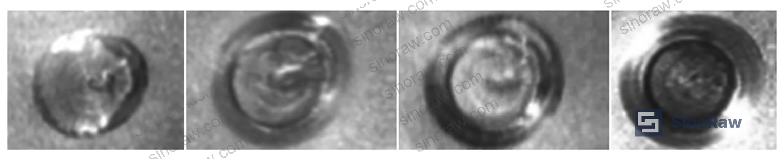
These aren’t conservative engineering margins — they’re the boundaries beyond which nugget size and geometry become inconsistent. Run outside these windows and you get either cold welds (insufficient fusion) or expulsion (material ejection, surface damage, dimensional distortion). Both failure modes compromise the mechanical integrity of the rail-to-backplate connection.
The four-stage welding cycle — pre-pressure, welding, hold, and rest — each serves a distinct mechanical function that can’t be compressed without quality consequence:
Pre-pressure stage (F > 0, I = 0): Establishes stable current path through the rail-backplate interface. Pressure must be matched to material type and thickness. Skip or shortcut this and you introduce contact resistance variability that undermines the entire thermal model.
Welding stage (F > 0, I > 0): Current flows, contact zone heats toward the metal’s melting point, nugget forms under sustained pressure. The combination of heat and pressure is what produces a dimensionally stable weld with minimal distortion — this is the primary advantage over fastener-based installation for high-volume assembly.
Hold stage (F > 0, I = 0): Current cuts off, pressure maintained, water cooling quenches the nugget rapidly. This is where nugget morphology is locked in. Premature pressure release here produces a porous, mechanically weak joint.
Rest stage (F = 0, I = 0): Electrode lifts, system resets to initial position.
The heat generated at the weld zone follows Joule’s law, where Q is a function of current squared, contact resistance (electrode-to-metal and metal-to-metal interfaces), bulk material resistance, and weld time. The dominant variable in practice is the metal-to-metal contact resistance — which is why backplate material uniformity is a critical constraint (more on that below).
This process is fully compliant with the kind of quality management traceability requirements outlined in ISO 9001:2015 Quality management systems, provided the supplier maintains parameter logs for each weld cycle — something worth verifying explicitly at audit.
Robotic Spot Welding System Architecture and Communication Protocol #
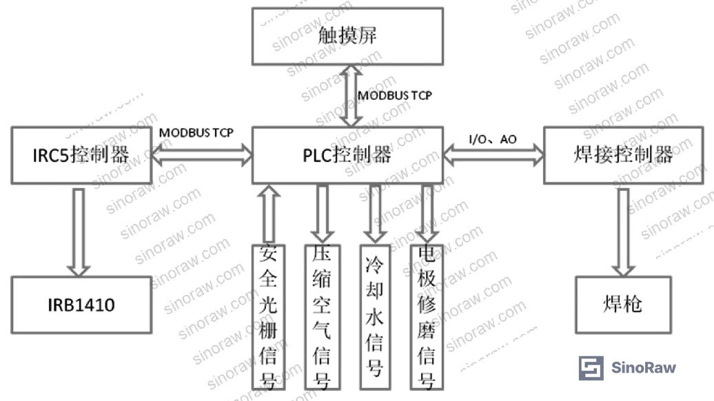
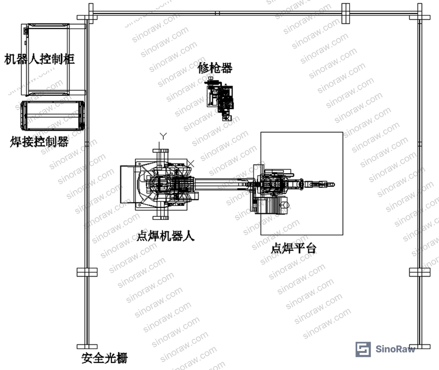
The validated system uses an IRB1410 robot body paired with an IRC5 controller — a combination that’s well-established in automotive and electronics assembly automation. The broader system includes: programmable logic controller (PLC), welding gun, welding controller, compressed air supply, cooling water circuit, and electrode dressing unit.
Communication between system nodes uses MODBUS TCP + digital I/O + analog signal — a protocol architecture chosen specifically for transmission speed, anti-interference characteristics, and long-distance signal integrity in industrial environments. This matters for buyers because it tells you something about the supplier’s automation maturity level. A MODBUS TCP-integrated welding cell with real-time fault detection is a different category of operation than a standalone spot welder with a manual log sheet.
On power-up, the system runs automatic initialization: checks robot home position, confirms weld completion status from prior cycle, verifies sensor status and air supply pressure. Safety signals are handled in two tiers — critical signals via hardwired connection triggering immediate machine stop, lower-priority signals managed through PLC-issued stop commands. During operation, any unit fault triggers automatic system halt with audio-visual alarm and fault display on the touchscreen, including component identification, fault cause, and corrective action.
Welding parameters — current, time, pressure, and position — are all set and adjustable via touchscreen interface. This configurability is both a strength and a risk: a well-trained operator can fine-tune for material variation, but a poorly trained one can drift parameters outside the validated window without realizing it.
Honestly, most buyers auditing cabinet assembly suppliers don’t ask about welding parameter management at all. They check certifications, inspect finished dimensions, and move on. That’s the gap where quality problems hide.
Practical Guidance for Buyers #
If you’re evaluating Chinese suppliers for DIN rail assemblies or control cabinet fabrication, the installation method deserves more scrutiny than it typically gets. Manual screw installation is labor-intensive, prone to torque inconsistency, and difficult to scale — but it’s also forgiving of backplate material variation. Robotic spot welding delivers better throughput and more consistent mechanical performance within its validated parameter window, but it has hard constraints.
The two unresolved technical barriers are real and worth probing:
First, backplate material standardization. PVC panels, galvanized steel, plain steel, and powder-coated panels all have different conductivity profiles. PVC is non-conductive and cannot be welded at all. A supplier claiming robotic spot welding installation must be specifying a conductive backplate material — and you should confirm which one, because this constrains your cabinet design options.
Second, DIN rail-to-component clip geometry. Individual electrical component manufacturers (PLCs, breakers, terminals) each use proprietary snap-fit profiles. There is no unified standard for the clip interface across vendors. This doesn’t affect the rail-to-backplate weld, but it affects downstream assembly workflow.
For sourcing Precision Fasteners or evaluating panel fabrication suppliers, understanding these constraints prevents expensive design rework mid-project. At sinoraw.com, our sourcing team works with verified Chinese manufacturers of industrial electrical components and panel assembly suppliers — we help overseas procurement engineers evaluate process capability and qualify suppliers before RFQs are issued.
Need help identifying qualified suppliers for robotic-welded DIN rail assemblies or control cabinet fabrication? Talk to our sourcing team →
Supplier Qualification Questions #
- What is your validated welding current setpoint for 1 mm DIN35 steel rail, and can you demonstrate that your process control holds deviation within ±20 A of that setpoint across a production batch?
- At your standard welding pressure of 2,250 N, what is your measured pressure fluctuation range, and how do you verify it remains within ±90 N of mean during a production run?
- What backplate materials have you validated for robotic spot welding — specifically, can you confirm that PVC and non-conductive backplate materials are excluded from your welded assembly process?
- What is your four-stage weld cycle timing (pre-pressure, weld, hold, rest) for 1 mm × 35 mm DIN rail, and do you maintain parameter logs per weld cycle or per batch?
- How does your system detect and respond to out-of-tolerance welding conditions — do you have automated halt logic tied to real-time current and pressure monitoring, or is quality verification done post-weld by inspection?
Sourcing Checklist #
- ☐ Supplier can provide weld parameter logs showing current deviation held within ±20 A of setpoint across a minimum 50-cycle production sample
- ☐ Welding pressure documented at 2,250 N ±300 N with fluctuation records showing ≤±90 N from mean
- ☐ Backplate material specification is defined and limited to conductive substrates (galvanized steel, plain steel) — PVC panels explicitly excluded from welded assembly scope
- ☐ Robot welding system uses a validated communication protocol (MODBUS TCP or equivalent) with real-time fault detection and automatic process halt capability
- ☐ Quality management system certified to ISO 9001:2015 with welding process records traceable to individual cabinet serial numbers
- ☐ Electrode dressing cycle frequency is documented and electrode condition is verified against a defined replacement schedule
- ☐ Supplier can demonstrate process compliance with ISO 14001:2015 Environmental management systems for welding fume and cooling water management
- ☐ Nugget inspection protocol is defined — either destructive cross-section testing per sample frequency or documented non-destructive verification method
Key Specifications Table #
| Parameter | Recommended Value | Verification Method |
|---|---|---|
| DIN rail profile (standard) | 35 mm (W) × 7.5 mm (D) × 1 mm (T) | Dimensional gauge / caliper per batch |
| Welding pressure | 2,250 N ±300 N | Force transducer on welding gun, log per cycle |
| Welding current deviation | Within ±20 A of setpoint | Real-time current monitoring, data log |
| Current fluctuation band | ≤40 A peak-to-peak | Waveform analysis on welding controller output |
| Pressure fluctuation | Within ±90 N of mean | Force log statistical analysis per batch |
| Backplate conductivity | Conductive metal only (no PVC) | Material certification + conductivity check at incoming inspection |
| Communication protocol | MODBUS TCP + digital I/O + analog | System architecture documentation / FAT protocol |
Can’t find a supplier meeting these specs? Submit your requirements and we’ll match you within 48 hours.
References #
Data source: Robotic Resistance Spot Welding as an Automated Mounting Method for DIN Rail in Electrical Control Enclosures, Z.-N. Guo et al., Journal of Manufacturing Processes, 2025
Frequently Asked Questions #
What is the standard DIN rail profile dimension used in electrical control cabinet assembly?
The most widely deployed profile is 35 mm wide × 7.5 mm deep × 1 mm thick, designated DIN35. This geometry is the basis for standardized mounting hardware from major electrical component manufacturers including PLCs, circuit breakers, power supplies, and terminal blocks.
Why does backplate material matter for robotic spot welding of DIN rail?
Resistance spot welding requires electrical conductivity through the joint interface. Non-conductive backplate materials — primarily PVC panels — cannot carry the welding current and are physically incompatible with this installation method. Galvanized steel and plain steel backplates are the validated substrate options. This is a hard constraint that limits which cabinet designs can use robotic welding, and it’s a question you need to ask any supplier claiming automated welding installation.
What failure modes should buyers watch for when qualifying a robotic DIN rail welding supplier?
Two are most common in practice. Cold welds — caused by insufficient current or pressure — produce a joint that looks acceptable on the surface but has inadequate mechanical strength; these typically fail under vibration or thermal cycling. Expulsion welds — caused by excessive current or insufficient hold time — eject molten material, damage the rail surface, and produce dimensionally unstable nuggets. Both failure modes occur when process parameters drift outside the validated window (±20 A current, ±300 N pressure), which is why parameter logging and real-time monitoring are non-negotiable qualification criteria.
Is robotic spot welding of DIN rail an industry-standard practice, or is it still emerging?
It’s still gaining adoption. Manual screw installation remains dominant across most cabinet fabricators, partly because it accommodates a wider range of backplate materials and requires no specialized tooling. Robotic welding is more common in high-volume automotive control panel production than in general industrial cabinet assembly. The lack of a unified standard for the DIN rail-to-component clip interface also complicates full-line automation — each electrical component vendor uses its own snap-fit geometry, so the weld step solves only part of the assembly automation challenge.
Can REACH Regulation (EC) No 1907/2006 compliance affect DIN rail material selection?
Yes, indirectly. If the DIN rail or backplate surface treatment involves zinc, chromate, or specific coating chemistries, REACH restrictions on certain substances of very high concern (SVHCs) may apply, particularly for equipment sold into European markets. Buyers sourcing Chinese-manufactured rail for EU-destined cabinet assemblies should request material declaration documentation and confirm that any surface treatment chemicals are REACH-compliant. ASTM D882 is not directly applicable here, but material traceability documentation follows the same logic: require it upfront, not after the order is placed.
Published by sinoraw.com Technical Team | Request a sourcing quote


