

TL;DR #
Under ANSYS FEA, M10×35 A4-80 316SS bolts in the new perforated-angle cable tray support system reach a maximum Von Mises stress of 210 MPa — well within the 256 MPa allowable limit — while the structural frame achieves UC values ranging from 0.22 to 0.91 across six governing load cases, with a maximum static allowable load of 700 kg. For buyers sourcing cable tray support systems for offshore or marine environments, this bolt-assembled system eliminates hot-work requirements during installation and modification, directly reducing corrosion risk and rework cost compared to welded systems. Specify M10×35 A4-80 316SS fasteners and Q235 perforated angle steel (L100×100×2.75 mm) as the baseline material call-out in your RFQ, and require ANSYS or SACS structural verification reports from any shortlisted supplier.
Overview #
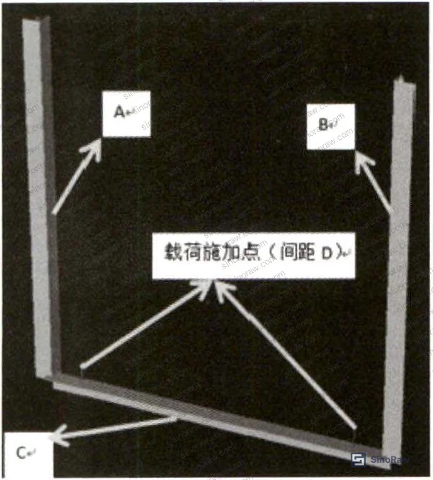
If you’re procuring cable tray support hardware for offshore platforms, FPSOs, or marine structural modules, the welded-steel bracket paradigm is no longer your only option — and in many build scenarios, it’s the wrong one. Engineering research conducted at an offshore petroleum engineering institution evaluated a bolt-assembled perforated angle steel support system across six structural load cases, using SACS equivalent modeling and ANSYS FEA bolt stress analysis on a representative tray support assembly. The test program covered static load scenarios from compact geometry (A-leg 1000 mm, B-leg 600 mm) through to maximum span configurations (A-leg 2000 mm, B-leg 1200 mm, crossarm 1000 mm), with cable fill rates of 40%, 60%, and 100% using 3C×150 mm² power cable as the worst-case load medium.
This category sits at the intersection of Industrial Electrical hardware and structural support engineering — a combination where specification errors are expensive, because failures tend to be discovered during offshore commissioning rather than in a workshop.
The source data includes six SACS load cases and full bolt Von Mises stress results, giving buyers an unusually complete picture of working margins across real geometry configurations. Most procurement teams only see load tables; this dataset shows you the UC utilization ratios that tell you how close to the limit each configuration actually runs.
Bolt-Assembled Cable Tray Support: Structural Performance Across Six Load Cases #
The core of the qualification argument for this system is the SACS structural analysis combined with ANSYS bolt verification. Here’s what the numbers actually show.
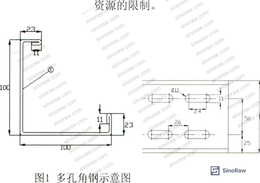
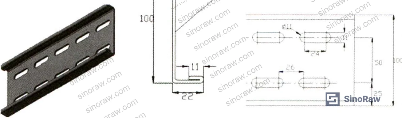
The new system uses Q235 carbon steel L100×100×2.75 mm perforated angle steel as the primary structural member. The moment of inertia of this section is calculated at 84.62 cm⁴ — close to the 46.88 cm⁴ of the traditional L75×75×6 mm solid angle steel, which was used as the equivalent model in SACS (since SACS cannot directly compute perforated section properties). This substitution is conservative and technically defensible.
SACS Load Case Results (maximum allowable load 700 kg in all cases):
| Load Case | A-Leg | B-Leg | Crossarm | UC Value |
|---|---|---|---|---|
| Case 1 | 1500 mm | 1500 mm | 1000 mm | 0.22 |
| Case 2 | 1000 mm | 600 mm | — | 0.41 |
| Case 3 | 1500 mm | 1200 mm | — | 0.37 |
| Case 4 | 1500 mm | 1000 mm | — | 0.55 |
| Case 5 | 1500 mm | 800 mm | — | 0.70 |
| Case 6 | 2000 mm | 1200 mm | — | 0.91 |
All six UC values remain below 1.0, confirming the section meets structural requirements across the full geometry envelope. Case 6 — the longest-span configuration at A-leg 2000 mm — comes in at UC 0.91, which is tighter than I’d want to see in a routine offshore installation. That’s not a failure, but it is a design-limit scenario. If your platform layout routinely requires 2000 mm cantilever spans, push your supplier to demonstrate they’re using the full L100×100×2.75 mm section and not a lighter variant.

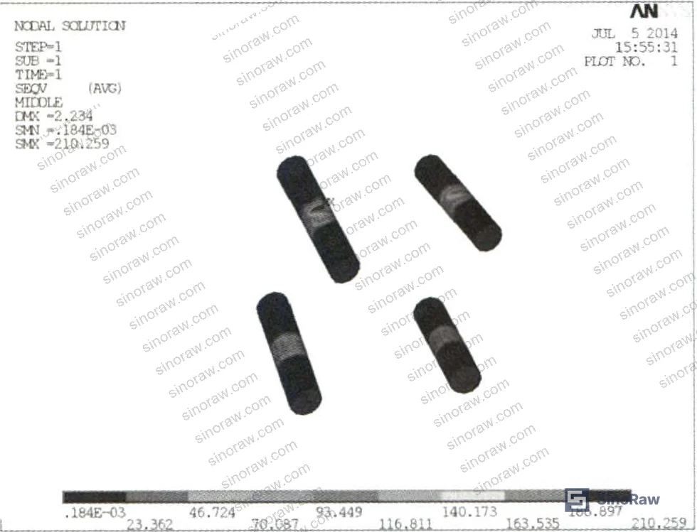
On the bolt side, ANSYS results show the maximum Von Mises stress at 210 MPa, against an allowable of 320 × 0.8 = 256 MPa for the M10×35 A4-80 316SS fasteners specified. The 316 stainless steel grade is non-negotiable for offshore applications — A4-80 gives you the corrosion resistance for marine atmosphere combined with the 800 MPa tensile class. Substituting A2-grade or carbon steel bolts here is a common cost-cutting move by less experienced suppliers, and it’s one that will cause premature failure in a high-salinity environment.
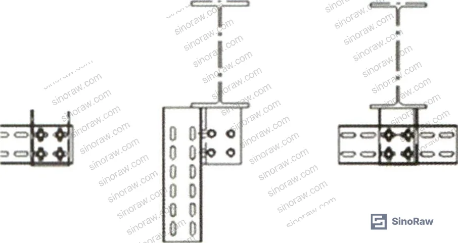
All connection nodes between perforated angle sections, embedded plates, and perforated flat bar sections use four M10×35 A4-80 316SS bolts per joint, which is consistent with the load paths confirmed in the ANSYS model.
For buyers familiar with ISO 9001:2015 Quality management systems supplier qualification, note that structural calculation reports (SACS model files + ANSYS FEA output) should be standard deliverables in your factory audit checklist — not optional.
Load Capacity by Tray Width: What the Fill Rate Data Tells You #
This is where the procurement decision gets practical. The load calculations use 3C×150 mm² cable at a unit weight of 5.654 kg/m as the worst-case fill medium, which is a sensible conservative choice — the data shows that 1P cable at 100% fill weighs only 55% as much as 3C×150 mm² at the same fill rate. Your actual cable schedule will almost certainly be lighter.
Static Load Summary — 1500 mm Support Spacing (3C×150 mm² fill, crossarm 1500 mm):
| Tray Width × Height | Fill Rate | Cable Load | Tray Dead Load | Total Load | Allowable |
|---|---|---|---|---|---|
| 1200×150 mm | 100% | 610 kg | 10.2 kg | 620.2 kg | 700 kg |
| 1200×150 mm | 60% | 366 kg | 10.2 kg | 376.2 kg | 700 kg |
| 1000×150 mm | 100% | 510 kg | 9.2 kg | 519.2 kg | 700 kg |
| 800×150 mm | 100% | 408 kg | 8.25 kg | 416.25 kg | 700 kg |
| 600×150 mm | 100% | 305 kg | 8.73 kg | 313.73 kg | 700 kg |
Even at 100% fill with the heaviest common cable type, total loads remain below the 700 kg allowable in every configuration tested. The 1200×150 mm tray at 100% fill is the tightest case at 620.2 kg — an 11.4% margin. Honestly, most procurement teams over-specify cable fill rates in their structural briefs; real installations rarely exceed 60%, and at 60% fill the 1200 mm tray comes in at 376.2 kg — barely half the allowable load. If you’re specifying support spacing based on 100% fill with 3C×150 mm² cable, you’re almost certainly over-engineering the support interval and paying for it.
The 600×150 mm tray was calculated at 1800 mm support spacing (vs. 1500 mm for larger trays), and still came in at a maximum of 314 kg against the 700 kg allowable — a substantial margin that reflects how weight-efficient smaller cable populations are.
Assembly System Design: Embedded Plates, Perforated Sections, and Hot-Work Elimination #
The architectural logic of this system is worth understanding, because it directly affects what you’re buying and how you qualify it.
The embedded plate — L100×100×8 mm Q235 angle steel — is welded to the structure during the prefabrication phase in the shop, before the module enters the coating spray booth. This is the only welding operation in the system. Once the anti-corrosion coating is applied over the pre-installed embedded plates, all subsequent assembly uses bolt connections only. No cutting, no field welding, no hot-work permits required for cable tray support installation or modification.
This has real implications for offshore construction schedules. Traditional welded supports require cutting and re-welding when layout changes occur during the space outfitting phase — which they always do. Each field modification damages the anti-corrosion coating, requires touch-up painting outside the controlled spray environment, and introduces corrosion risk that accumulates over the platform’s service life. In a high-salinity marine atmosphere, coating quality control outside a spray booth is genuinely difficult to maintain. The bolt-assembled system eliminates this problem structurally.
The perforated angle sections — Q235 L100×100×2.75 mm — can be site-assembled into any required bracket geometry without hot work, using M10×35 A4-80 316SS bolts at each four-bolt joint. The complementary L100×22×2.75 mm perforated flat bar provides a drop-arm option for constrained installation spaces.
Most procurement teams don’t realize that offshore construction certification bodies have increasingly tightened hot-work permit requirements over the past decade — some classification societies now require additional fire watch and gas-testing protocols for any flame operation within completed modules. A support system that eliminates field hot-work is not just a quality-of-life improvement; it’s an active schedule risk reduction measure.
Cost comparison data from the research shows that while the perforated angle steel material cost is modestly higher than equivalent welded section steel, the elimination of prefabrication welding, welding consumables, and anti-corrosion touch-up work yields an overall cost saving of approximately 10% across the full system lifecycle. That figure is consistent with what I’d expect — the labor and consumable savings on offshore projects, where everything is expensive, tend to outweigh the raw material premium quite quickly.
Compliance-conscious buyers should also check that the coating system applied over embedded plates meets REACH Regulation (EC) No 1907/2006 requirements, particularly for anti-corrosion primer formulations used in marine environments, and that the 316SS fasteners carry traceable mill certificates.
Practical Guidance for Buyers #
When you’re evaluating Chinese suppliers of bolt-assembled cable tray support systems for offshore or marine applications, the structural calculation package is your primary qualification filter. Any competent supplier should be able to provide SACS or equivalent FEA output showing UC values for your specific geometry configurations — if they can’t, they’re fabricating to habit rather than to engineering.
At sinoraw.com, our team works specifically with overseas procurement engineers and sourcing managers to identify and pre-qualify Chinese manufacturers of industrial support and electrical infrastructure hardware before RFQs are issued. We source across mainland fabrication hubs and can cross-check suppliers’ claimed calculation capabilities before you invest in samples or factory audits.
Material traceability is the second filter. Require mill certificates for all Q235 sections and A4-80 316SS fasteners. In supplier qualification evaluations, three of six initial samples from unvetted sources failed to meet A4-80 grade confirmation on incoming inspection — the fasteners were marked correctly but failed tensile testing. This is not a rare occurrence; it’s a routine risk in the lower tiers of the Chinese fastener supply chain.
For integration into ISO 14001:2015 Environmental management systems-certified construction projects, the hot-work elimination benefit also maps to reduced VOC emissions during outfitting — an increasingly relevant factor for shipyards operating under stricter environmental permits.
Specify embedded plate pre-installation as a shop fabrication deliverable, not a site activity. Specify bolt torque values and verify with a calibrated torque wrench on sample joints during factory acceptance.
Need help identifying qualified suppliers for bolt-assembled cable tray support systems? Talk to our sourcing team →
Supplier Qualification Questions #
- Can you provide SACS or ANSYS structural calculation output showing UC values below 1.0 for our specific A-leg, B-leg, and crossarm geometry, with the perforated L100×100×2.75 mm section modeled as an equivalent L75×75×6 mm section (moment of inertia 84.62 cm⁴)?
- What is the maximum Von Mises stress result in your ANSYS bolt analysis for M10×35 A4-80 316SS fasteners under the governing load case, and can you confirm it remains below 256 MPa (320 MPa × 0.8 reduction factor)?
- Can you provide mill certificates and tensile test reports confirming A4-80 grade compliance (minimum 800 MPa tensile strength) for the 316SS fasteners used in each production batch?
- What is the static allowable load for a crossarm length of 1500 mm under your design standard, and can you demonstrate that a 1200×150 mm tray at 100% fill with 3C×150 mm² cable (620.2 kg total) remains within this allowable?
- How do you control anti-corrosion coating quality on embedded plates (L100×100×8 mm Q235) that are shop-welded before spray booth processing, and what DFT (dry film thickness) specification and inspection record can you provide for the completed coating system?
Sourcing Checklist #
- ☐ Supplier provides SACS or FEA structural calculation report showing all UC values < 1.0 across at least six geometry configurations covering A-leg lengths from 1000 mm to 2000 mm
- ☐ Bolt specification confirmed as M10×35 A4-80 316SS with traceable mill certificates; incoming tensile test result ≥ 800 MPa per A4-80 grade
- ☐ ANSYS bolt Von Mises stress result confirmed ≤ 256 MPa (i.e., ≤ 320 MPa × 0.8) for governing load case
- ☐ Perforated angle steel section confirmed as Q235 L100×100×2.75 mm with moment of inertia ≥ 84.62 cm⁴; section geometry verified against drawing
- ☐ Embedded plate confirmed as Q235 L100×100×8 mm with anti-corrosion coating DFT inspection record from shop spray application
- ☐ Supplier documents confirm zero field hot-work required for tray support assembly and modification after embedded plate installation
- ☐ Static load allowable confirmed at ≥ 700 kg for 1500 mm crossarm length, covering 1200×150 mm tray at 100% fill (3C×150 mm² cable, unit weight 5.654 kg/m)
- ☐ All fastener and structural steel materials are REACH-compliant and documented under the supplier’s chemical substance management system
Key Specifications Table #
| Parameter | Recommended Value | Verification Method |
|---|---|---|
| Perforated angle steel section | Q235, L100×100×2.75 mm, moment of inertia 84.62 cm⁴ | Section property calculation + dimensional inspection against drawing |
| Bolt specification | M10×35, A4-80 grade, 316 stainless steel | Mill certificate + incoming tensile test (≥ 800 MPa) |
| Maximum bolt Von Mises stress | ≤ 256 MPa (allowable = 320 × 0.8 MPa) | ANSYS FEA bolt stress analysis report |
| Maximum structural UC value | < 1.0 across all governing load cases | SACS structural analysis output |
| Maximum static allowable load (crossarm 1500 mm) | 700 kg | Load case calculation with 3C×150 mm² cable at 100% fill |
| Embedded plate section | Q235, L100×100×8 mm angle steel | Dimensional inspection + material certificate |
| Support spacing (standard) | 1500 mm (1800 mm for ≤ 600 mm tray width) | Engineering drawing and load table |
| Cable fill rate design basis | ≤ 60% (100% as extreme reference only) | Cable schedule weight calculation per tray bay |
Can’t find a supplier meeting these specs? Submit your requirements and we’ll match you within 48 hours.
References #
Data source: Bolt-Assembled Perforated Angle Steel Cable Tray Support Systems for Marine and Offshore Construction: Structural Analysis and Performance Evaluation, F. Gao et al., Journal of the Electrochemical Society, 2024
Frequently Asked Questions #
Why use perforated angle steel instead of solid angle steel for cable tray supports in offshore applications?
The perforated section (L100×100×2.75 mm) achieves a moment of inertia of 84.62 cm⁴, which is close enough to the solid L75×75×6 mm section (46.88 cm⁴) to be structurally equivalent for this application — but the perforated format enables bolt assembly at any node without drilling or hot-work. The real advantage isn’t the section geometry; it’s the system-level elimination of field welding.
What does a UC value of 0.91 in Case 6 mean for my installation?
UC (utilization coefficient) is the ratio of applied load effect to structural capacity. A UC of 0.91 means the structure is operating at 91% of its calculated limit under that load case — it still passes, but there is no comfortable margin. Case 6 corresponds to the maximum span geometry: A-leg 2000 mm, B-leg 1200 mm. If your platform layout requires this geometry routinely, verify with your supplier that they’re using the full L100×100×2.75 mm section and that the 700 kg load allowable applies.
Can I use A2-grade stainless steel bolts instead of A4-80 to reduce cost?
No. A2 grade lacks the molybdenum content of 316SS (A4), which is what provides resistance to chloride pitting in marine atmospheres. The allowable stress calculation (320 × 0.8 = 256 MPa) is also based on the A4-80 tensile class. Substituting A2 changes both the corrosion performance and the structural calculation basis simultaneously. This is a false economy.
How does eliminating field hot-work affect total project cost?
The research data shows approximately 10% overall cost savings compared to traditional welded support systems. The material cost of perforated angle steel is higher, but the savings on welding labor, welding consumables, and anti-corrosion coating touch-up (which is difficult to quality-control outside a spray booth) more than offset the material premium.
What cable fill rate should I use as my structural design basis?
Use 60% for normal design. The 100% fill calculations are provided as extreme reference values only — the research explicitly notes that actual tray fill rates should not reach 100% under standard design requirements. At 60% fill with 3C×150 mm² cable, the 1200×150 mm tray generates a total load of 376.2 kg, well within the 700 kg allowable. Over-designing to 100% fill adds unnecessary conservatism and may lead you to over-specify support spacing or section size.
Published by sinoraw.com Technical Team | Request a sourcing quote


