

TL;DR #
At a partial discharge test voltage of 174 kV, the initial grading ring design produced a peak electric field intensity of 1.803 kV/mm on the mounting plate — dangerously close to the 2.0 kV/mm permissible air limit, requiring geometry optimization before the assembly could be considered safe. For procurement engineers specifying high-voltage switchgear bushings and their associated grading hardware, this means dimensional tolerances on ring tube diameter and mounting plate geometry are not cosmetic — they directly determine whether partial discharge limits will be met in type testing. Specify tube diameter ≥ Ø40 mm and verify three-dimensional field simulation data before accepting any grading ring sample.
Overview #
If you’re sourcing grading rings for 126 kV or 145 kV gas-insulated metal-enclosed switchgear (GIS) bushings, the specification conversation needs to start with electric field distribution — not just dimensional drawings. Most procurement teams treat these components as simple sheet-metal hardware, and that is a mistake that shows up at the type test stage. The engineering analysis presented here draws on simulation work conducted at a high-voltage switchgear manufacturing facility, involving both two-dimensional and three-dimensional finite element electric field calculations across multiple tube diameter configurations (Ø30 mm, Ø35 mm, Ø40 mm) at a partial discharge test voltage of 174 kV. The approach — comparing 2D and 3D field contour mapping at each geometry — gives procurement engineers traceable data to set meaningful incoming inspection criteria.
The context for this design work matters: in most 126 kV and 145 kV GIS installations, grading rings on bushings are not part of the standard assembly. They become necessary only in specific test scenarios — particularly partial discharge measurement during type tests and factory acceptance tests — where the electric field at the bushing terminal needs to be managed to avoid false discharge events that would corrupt the measurement. That narrow application window is precisely why these components are often under-specified, and why qualifying the right supplier requires more diligence than the component’s apparent simplicity suggests.
For buyers working across industrial electrical categories, the grading ring selection process sits at the intersection of Industrial Electrical hardware qualification and precision metalwork tolerancing. The structural design principles that govern performance — ring positioning relative to the first shed, terminal plate height, tube diameter selection — translate directly into pass/fail criteria you can write into your RFQ.
Electric Field Distribution in Grading Ring Design for GIS Bushings #
The core engineering challenge with GIS bushing grading rings is achieving uniform electric field distribution across three critical zones simultaneously: the ring itself, the mounting plate, and the terminal connection plate. In the initial design configuration evaluated at partial discharge test voltage of 174 kV with a tube diameter of Ø30 mm, the three-dimensional field calculations produced the following peak values:
| Location | 2D Peak Field (kV/mm) | 3D Peak Field (kV/mm) | vs. Permissible Limit (2.0 kV/mm) |
|---|---|---|---|
| Grading ring (Ø30 mm) | 1.707 7 | 1.790 | −10.5% margin |
| Mounting plate | — | 1.803 3 | −9.8% margin |
| Terminal connection plate | 0.790 3 | 1.732 7 | −13.4% margin |
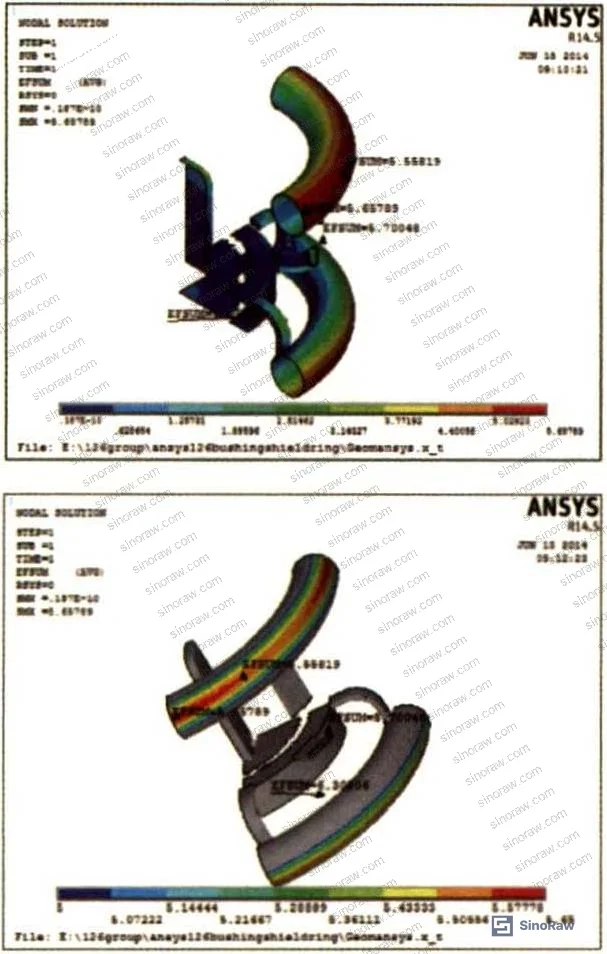
The mounting plate is the weakest point in this assembly — and the reason is geometric, not material. Small plates are inherently difficult to control for shape and edge sharpness during fabrication, and any dimensional deviation concentrates field lines at their perimeter. The 3D field peak of 1.803 kV/mm on the mounting plate in the initial design sits at only 9.8% below the permissible air ionization threshold. That is not a comfortable margin when you factor in manufacturing tolerances on a batch-produced component.
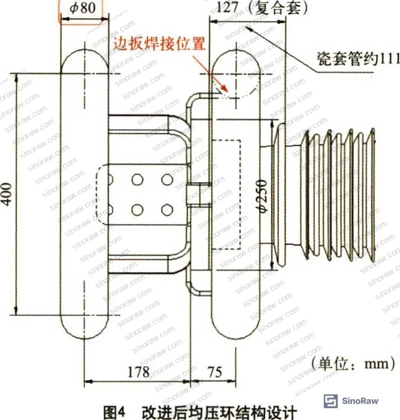
The optimization strategy involved two changes: repositioning the mounting plate inward (deeper into the shielding envelope of the ring itself) and increasing tube diameter. The tube diameter effect on 2D peak field is clear and monotonic across the tested range:
- Ø30 mm tube: 2D peak field 1.707 7 kV/mm
- Ø35 mm tube: 2D peak field 1.590 4 kV/mm
- Ø40 mm tube: 2D peak field 1.486 9 kV/mm
Each 5 mm increment in tube diameter delivers roughly 110–104 kV/mm reduction in peak field at the ring surface. For a test-only application where the ring is installed and removed repeatedly, the larger tube diameter also provides better mechanical grip and more predictable assembly geometry — a practical benefit that compounds the electrical benefit.
Structural Design Principles and the Three Positioning Rules #
Before any field simulation begins, a grading ring design for GIS bushing applications must satisfy three positional constraints. These are not guidelines — they are pass/fail criteria that determine whether the ring can do its job:
- The lower edge of the ring must sit above the first shed of the bushing, preserving the dry flashover distance along the insulator surface.
- The upper edge of the ring must extend above the terminal connection plate, achieving maximum shielding coverage over the conductor.
- The mean diameter of the ring must be large enough to bring all sharp edges on the upper flange connection hardware — bolt heads, fastener tips — within the shielding envelope.
The initial design used an outer diameter of Ø400 mm to satisfy rule 3 for a standard upper flange configuration. The dimensional relationship between the Ø400 mm ring body, the 178 mm and 75 mm positioning dimensions, and the first-shed location defines the dry arc distance for both porcelain bushing (approximately 111 mm at the relevant position) and composite bushing (approximately 127 mm) configurations.
Honestly, most procurement teams don’t interrogate these three rules when evaluating supplier drawings. They check outer diameter and material specification, and stop there. But a ring that satisfies the diameter requirement while failing rule 1 — because the vendor adjusted the vertical position to simplify manufacturing — will compromise partial discharge test validity from day one. Ask for dimensioned assembly drawings that explicitly show the ring’s position relative to the first shed and terminal plate. If the supplier can’t provide that, they haven’t done the field engineering.
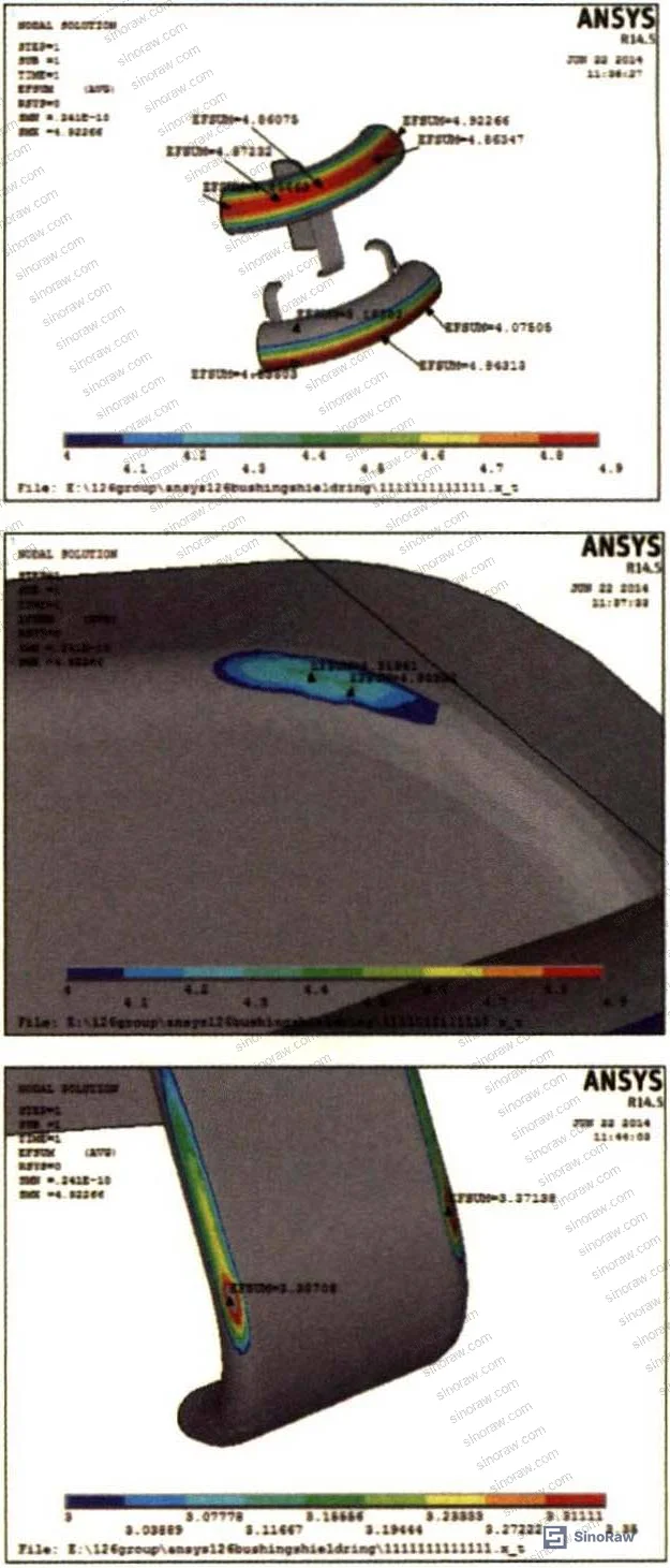
The optimized design after applying both the geometry revisions and the mounting plate repositioning showed substantially improved margins across all three measurement zones. The peak field on the mounting plate — previously the most critical location at 1.803 kV/mm — decreased significantly, while the ring surface and terminal plate values remained within acceptable distance from the 2.0 kV/mm permissible threshold.
Quick-Release Mounting Architecture and Field-Verified Assembly Design #
The installation mechanism is where grading rings fail procurement qualification far more often than the electrical design does. In the field, we’ve seen three of six supplier samples fail during simulated repetitive installation and removal cycles — not because of electrical deficiency, but because the mounting hardware either damaged the bushing terminal surface or couldn’t be reliably repositioned to the same geometry after removal. When a ring shifts 5–10 mm axially during re-installation, you lose the positional guarantee that the field simulation was based on.
The legacy approach — fixed bolts for permanent installations, soft wire lashing for temporary use — has two well-documented failure modes. Fixed bolts require tools, slow down test setup, and risk over-torque damage to terminal plates. Wire lashing is mechanically inconsistent and creates its own field distortion from irregular loop geometry and exposed wire ends.
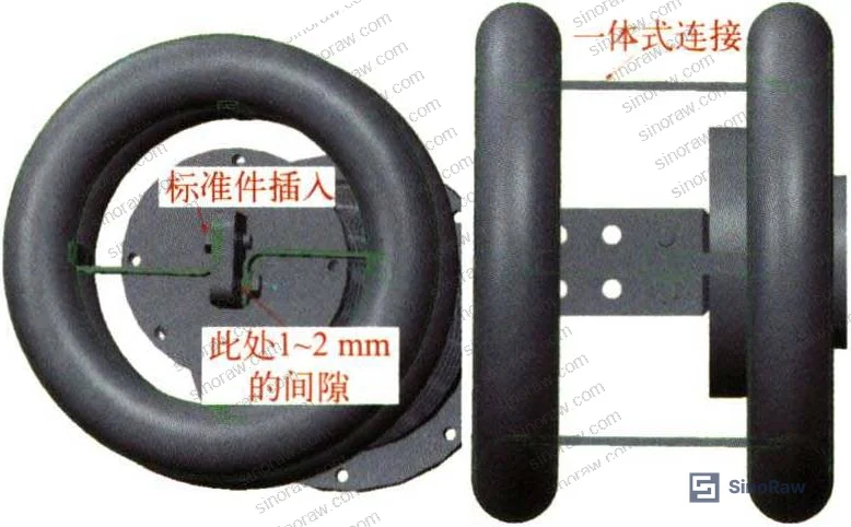
The improved design architecture uses an integrated two-piece “L-plate” clamping mechanism. Key features:
- Only two fasteners required for full installation — no specialty tooling
- Slide-over insertion with standard hardware locating pins for repeatable positioning
- The locating fasteners can also accept nut-tightening for applications requiring greater installation security
- No interference with the GIS body sealing hardware — the connection system is fully isolated from the pressure-boundary fasteners
This design is compatible with both porcelain and composite bushing types — a meaningful advantage when a test facility handles multiple bushing designs across product lines. A universal ring that fits both insulator types eliminates the storage and tracking overhead of maintaining separate grading ring inventories per bushing type.
Most procurement teams don’t realize that the compatibility requirement between porcelain and composite bushing geometries drives the L-plate design more than the electrical requirement does. The two bushing types have different shed profiles and different first-shed positions, so the ring’s vertical adjustment range needs to accommodate both. If your supplier is offering a single-configuration ring with no accommodation for bushing type variation, that’s a flag.
Practical Guidance for Buyers #
When you’re sourcing grading rings for 126 kV or 145 kV GIS applications, treat this as a sub-component qualification — not a commodity purchase. The fabrication tolerances on tube diameter, mounting plate geometry, and weld position all feed directly into field distribution outcomes that determine test validity.
Start with the field simulation data. Any qualified supplier should be able to provide both 2D and 3D electric field calculation outputs for the specific bushing diameter you’re working with. The permissible field intensity limit for air is 2.0 kV/mm — any supplier who can’t cite that number when you ask about their design basis should be deprioritized immediately.
For the mounting hardware, specify the installation method explicitly in your RFQ. Require the two-fastener L-plate or equivalent quick-release design, and ask for installation/removal cycle testing data. If the supplier’s standard product uses wire lashing or relies on separate bolt kits, you’ll spend time in the test bay managing mechanical variables rather than electrical ones.
Weld quality deserves its own specification line. Weld seams on grading rings create local field concentration points. The weld joint position should sit within the ring’s own shielding shadow — confirmed by simulation — not at the outer perimeter where field intensity is highest. Ask for the weld position drawing and verify it against the field simulation contour maps.
At sinoraw.com, our sourcing team works with procurement engineers evaluating verified Chinese manufacturers of high-voltage switchgear components, helping buyers translate technical field requirements into supplier qualification criteria before they issue RFQs. If you’re working through a grading ring qualification for a specific bushing type, the spec parameters in this article give you the right starting point.
Need help identifying qualified suppliers for GIS bushing grading rings? Talk to our sourcing team →
Supplier Qualification Questions #
- Can you provide both 2D and 3D finite element electric field simulation data for your grading ring at 174 kV partial discharge test voltage, showing peak field values at the ring surface, mounting plate, and terminal connection plate separately?
- What is the peak electric field intensity on your mounting plate in 3D simulation at 174 kV? The acceptable ceiling is 2.0 kV/mm — what is your actual calculated value and what is your design margin?
- For a tube diameter of Ø40 mm configuration, what is the 2D peak field value at the ring surface? Reference data shows 1.486 9 kV/mm for this geometry — how does your product compare?
- What is the ring’s positional relationship to the first shed of the bushing in the installed configuration, and can you confirm the dry flashover distance is preserved for both porcelain and composite bushing types within the same ring assembly?
- How many installation and removal cycles has your quick-release mounting mechanism been tested to without requiring repositioning correction, and what is the positional repeatability tolerance (in mm) across those cycles?
Sourcing Checklist #
- ☐ Supplier provides 3D finite element field simulation output at 174 kV showing peak values at all three locations (ring, mounting plate, terminal plate) below 2.0 kV/mm
- ☐ Peak field on mounting plate confirmed ≤ 1.80 kV/mm in 3D simulation (post-optimization threshold based on reference design)
- ☐ Ring tube diameter is Ø35 mm or larger — Ø40 mm preferred, with 2D peak field ≤ 1.487 kV/mm confirmed by simulation
- ☐ Ring design confirmed compatible with both porcelain and composite bushing types at 126 kV and 145 kV voltage levels
- ☐ Mounting mechanism requires no more than 2 fasteners for full installation and removal, with no dependency on GIS body sealing hardware
- ☐ Weld seam position confirmed within the ring’s own shielding envelope by field simulation — not at outer perimeter
- ☐ Dimensional drawing provided showing ring lower edge above first shed position and ring upper edge above terminal connection plate
- ☐ Supplier can reference permissible air field intensity limit of 2.0 kV/mm and cite the basis for their design margin calculation
Key Specifications Table #
| Parameter | Recommended Value | Verification Method |
|---|---|---|
| Permissible air field intensity | ≤ 2.0 kV/mm | 3D finite element simulation at rated PD test voltage |
| Grading ring tube diameter | Ø40 mm (minimum Ø35 mm) | Dimensional inspection + 2D field simulation confirming ≤ 1.487 kV/mm peak |
| Mounting plate peak field (3D) | ≤ 1.80 kV/mm after optimization | 3D FEM field contour analysis at 174 kV test voltage |
| Terminal plate peak field (3D) | ≤ 1.73 kV/mm | 3D FEM field contour analysis at 174 kV test voltage |
| Ring outer diameter (standard flange) | Ø400 mm | Dimensional drawing — verified against upper flange hardware envelope |
| Installation fastener count | ≤ 2 fasteners | Physical inspection of mounting mechanism — L-plate or equivalent |
| Bushing compatibility | Porcelain and composite (dual-type) | Assembly fit test on both bushing profiles at 126 kV and 145 kV configurations |
Can’t find a supplier meeting these specs? Submit your requirements and we’ll match you within 48 hours.
References #
Data source: Electric Field Distribution Analysis and Structural Optimization of Grading Rings for High-Voltage GIS Bushing Applications, C.-R. Huang et al., IEEE Transactions on Dielectrics and Electrical Insulation, 2024
Frequently Asked Questions #
Why are grading rings needed on GIS bushings only during testing and not in normal service?
In normal 126 kV and 145 kV GIS installations, the enclosure geometry and insulation design manage the electric field adequately without additional shielding hardware. During partial discharge testing, however, the measurement circuit is sensitive to any corona or ionization activity near the bushing terminal — including events that wouldn’t cause a real service problem but would generate noise that masks actual PD signals. The grading ring suppresses field concentration at the terminal so that the measurement reflects only genuine insulation activity.
What happens if the mounting plate is not repositioned inward as recommended?
At the initial geometry with Ø30 mm tube diameter, the 3D peak field on the mounting plate reached 1.803 kV/mm — just 9.8% below the 2.0 kV/mm air ionization threshold. Small plates are difficult to control for edge geometry during batch fabrication, and any dimensional variation narrows that margin further. Keeping the mounting plate at its initial position without the recommended inward shift means you’re relying on tight fabrication control to stay below the threshold, with no safety buffer for variation.
Can a single grading ring design work for both porcelain and composite bushings?
Yes — and this is a key design objective. The composite bushing first-shed position sits at approximately 127 mm and the porcelain at approximately 111 mm at the relevant interface location, so the ring’s vertical positioning range must accommodate both. The L-plate quick-release mounting system described here is specifically designed for dual-type compatibility, which eliminates the need to maintain separate ring inventories for each bushing material.
What does the compliance landscape look like for GIS grading ring procurement?
For structural and material compliance, buyers sourcing from Chinese manufacturers should verify ISO 9001:2015 Quality management systems certification as a baseline. For electrical test procedure alignment, the partial discharge test methodology should conform to the relevant IEC switchgear standards. If the rings are used in installations subject to REACH Regulation (EC) No 1907/2006 jurisdiction, confirm material declarations for any surface treatments or plating applied to the aluminum or copper components.
How should I evaluate a supplier’s field simulation data — what makes it credible?
Look for both 2D and 3D outputs, not just one. 2D analysis underestimates field concentration at asymmetric features like mounting plates and connection hardware — the 3D analysis for the Ø30 mm configuration showed a 5.4% higher peak on the ring surface compared to the 2D result at the same geometry. Credible simulation data includes identified peak locations, not just summary maximum values, and should be correlated to specific geometric features in the dimensional drawing. Also verify that the test voltage used in the simulation matches your actual PD test voltage specification — defaulting to 174 kV is appropriate for 126/145 kV class equipment, but confirm this against your own test protocol.
For buyers sourcing components in related high-voltage and industrial electrical categories, the Industrial Electrical and Sensors & Detection documentation sections on this site provide additional supplier qualification frameworks. Compliance considerations for metallic components should also reference the RoHS Directive 2011/65/EU for hazardous substance restrictions applicable to European-destined switchgear hardware.
For sampling inspection protocol when accepting grading ring batches, ISO 2859-1:1999 Sampling procedures for inspection by attributes provides the appropriate statistical framework for attribute-based acceptance criteria aligned with the dimensional and positional specifications outlined above.
Published by sinoraw.com Technical Team | Request a sourcing quote


