

TL;DR #
Under low-pressure hydraulic conditions (0–1.5 MPa), NBR O-rings with higher compression ratios consistently outperform lower-compression counterparts as oil pressure increases — a finding validated by both FEA simulation and physical leakage testing on a purpose-built reciprocating test bench. For procurement engineers specifying O-rings for hydraulic actuators, pump housings, or valve stems operating in this pressure range, compression ratio selection is not a secondary detail — it is the primary sealing variable. Specify a minimum compression ratio of 15–20% for dynamic seal applications and require suppliers to provide contact stress simulation data or leakage rate test results before approving a seal design.
Overview #
If you’re sourcing NBR O-rings for hydraulic pump or valve actuator applications and you’re relying solely on cross-section diameter and inner diameter to qualify a supplier, you’re leaving the most critical performance variable off the table. Compression ratio and seal mode (static vs. dynamic) determine whether your O-ring holds at 0.5 MPa or leaks at 1.0 MPa — and most supplier datasheets don’t tell you which.
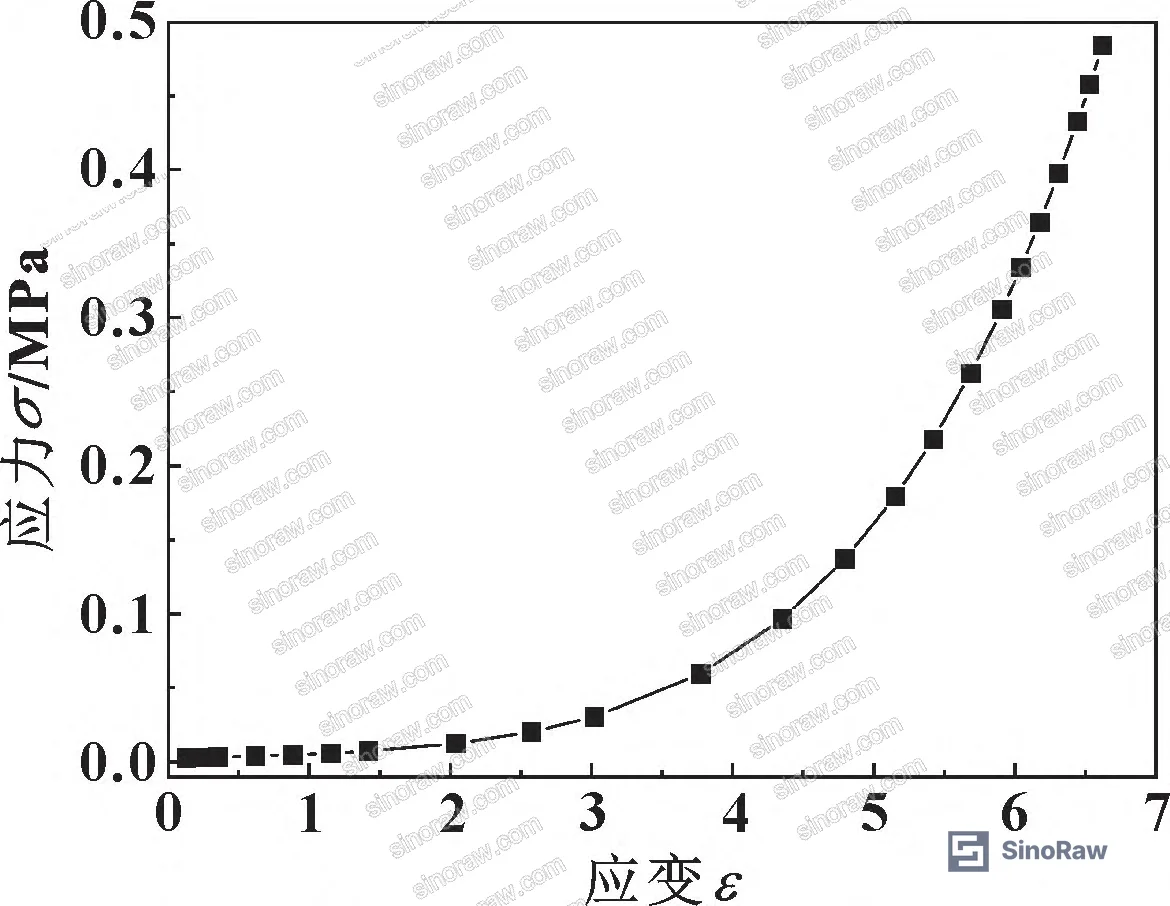
The analysis summarized here draws on combined finite element simulation and experimental validation conducted at a Chinese aerospace engineering institution, using a custom-built low-pressure reciprocating seal test bench capable of measuring both contact stress and average leakage rate simultaneously. The test geometry used NBR O-rings with an inner diameter of 20 mm, wire diameter of 3.6 mm, groove width of 4 mm, and groove depth of 3 mm — dimensions representative of actuator-grade seals. Four compression ratios were evaluated across a pressure sweep from 0 to 1.5 MPa, under both static and dynamic (reciprocating) seal conditions. The Mooney-Rivlin two-parameter hyperelastic constitutive model was used to characterize NBR material behavior, with elastic modulus confirmed at 14.04 MPa and Poisson’s ratio at 0.499.
This is the kind of data that separates a technically competent seal supplier from one who can only quote you a hardness value and a Shore A number.
For buyers sourcing pump and valve seals from Chinese manufacturers, understanding the mechanics behind compression ratio and dynamic torsion behavior is essential to writing a specification that actually filters out underperforming product.

O-Ring Compression Ratio and Contact Stress Under Low-Pressure Static Sealing #
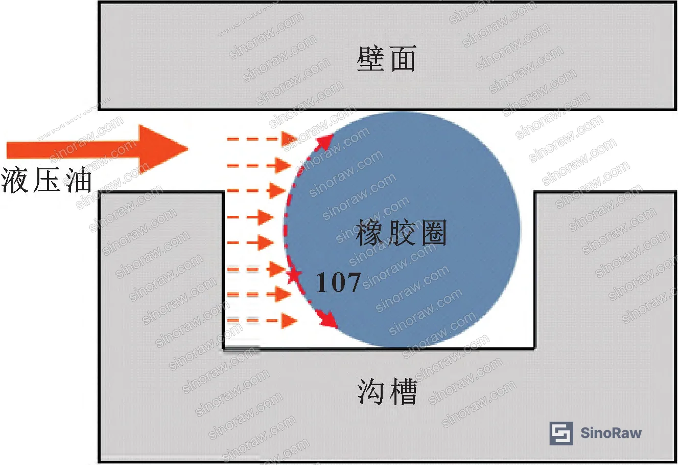
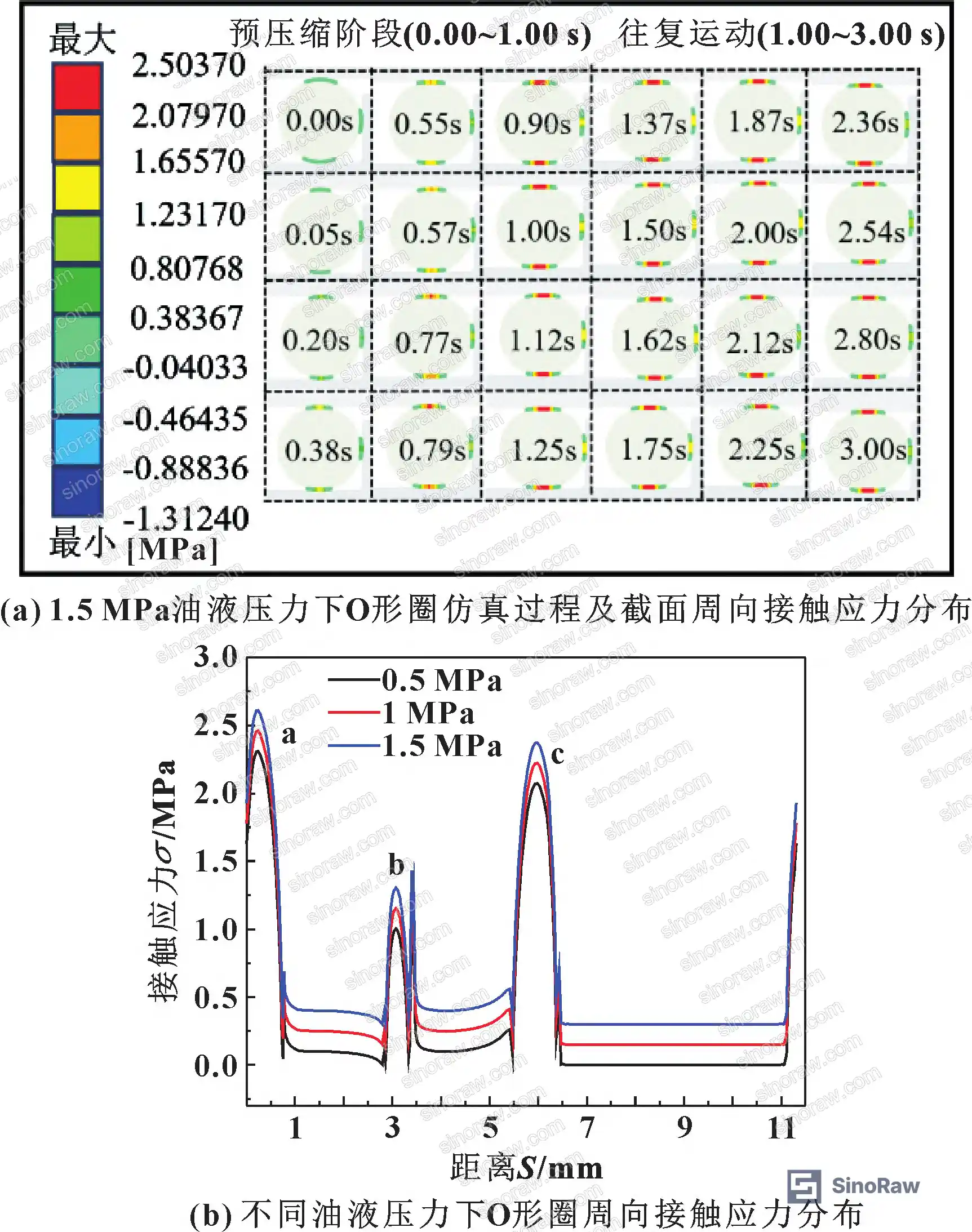
The sealing mechanism of an O-ring is straightforward in principle but surprisingly easy to misapply in procurement. When an O-ring is installed in a groove and compressed against a mating wall, it generates contact stress at three interfaces: the groove bottom (surface a), the groove sidewall (surface b), and the primary sealing wall (surface c). Sealing is achieved when the contact stress at surface c exceeds the fluid pressure trying to push through. That’s the entire mechanism — and compression ratio is what sets the baseline contact stress before any fluid pressure is applied.
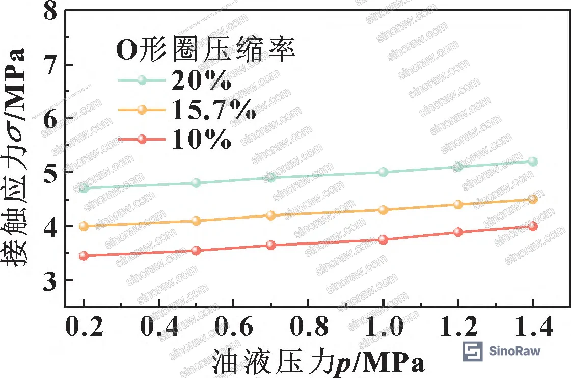
At 10% compression under 1.5 MPa oil pressure, FEA results show three distinct contact stress peaks corresponding to the three sealing surfaces. The primary contact face (surface c, wall-facing) carries the dominant sealing load. As compression ratio increases across the tested range, the peak contact stress at this primary interface rises significantly — confirming that higher compression ratios provide greater sealing margin against the applied fluid pressure.
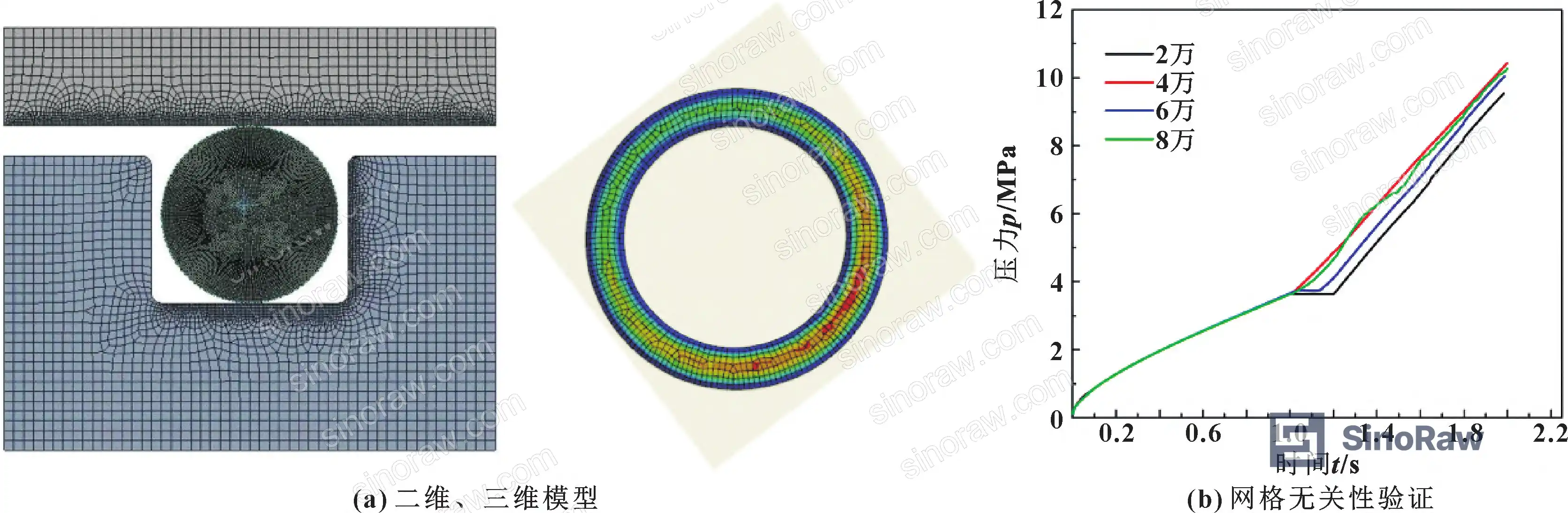
The FEA mesh was validated for grid independence: results stabilized within 10% error once mesh count exceeded 40,000 elements. The final model used 15,304 elements and 47,223 nodes — sufficient resolution to capture the stress gradient at the contact interface without excessive computational cost.
Comparison of O-Ring Performance Variables Under Low-Pressure Conditions (0–1.5 MPa)
| Parameter | Static Seal | Dynamic Seal (Reciprocating) |
|---|---|---|
| Contact stress trend with increasing oil pressure | Increases proportionally with compression ratio | Increases at extrusion end; decreases at relaxation end |
| Effect of higher compression ratio | Significantly higher contact stress, better sealing | Superior sealing at higher pressures; torsion amplifies contact stress at extrusion end |
| Leakage rate trend | Decreases as oil pressure increases (all compression ratios) | Higher than static at same compression ratio; high-compression O-rings outperform low-compression at elevated pressure |
| Dominant failure mode | Insufficient contact stress at primary sealing face | Uneven stress distribution due to rolling torsion; relaxation-end contact stress drops below static seal level |
| Material (tested) | NBR, E = 14.04 MPa, ν = 0.499 | NBR, E = 14.04 MPa, ν = 0.499 |
Honestly, most buyers over-specify O-ring hardness (Shore A) and under-specify compression ratio. Shore A tells you about bulk material stiffness — it says almost nothing about how the seal will perform at 0.8 MPa in a reciprocating actuator groove. The data here makes it clear: compression ratio is the variable that actually governs contact stress at the sealing interface.
For reference on international standards governing seal testing methodology, IEC 61960-3 Secondary lithium cells and batteries for portable applications provides a useful framework for understanding how test bench validation protocols are structured in precision component qualification — the same rigor applies to hydraulic seal test bench design.
Dynamic Seal Torsion Behavior and Its Effect on NBR O-Ring Sealing Performance #
This is where the research gets genuinely useful for procurement engineers — and where most seal qualification protocols fall short.
Under dynamic (reciprocating) conditions, the O-ring does not simply slide along the groove wall. It rolls and twists. As the mating wall moves in one direction, the contact-side rubber deforms first, creating a single-sided compression-relaxation cycle that repeats with each stroke reversal. The torsion angle — measured at a defined internal node relative to the O-ring centerline — cycles in phase with wall displacement. At the reversal points of the reciprocating stroke, torsion is most pronounced, and a visible torsion gap appears on the inner face of the O-ring.
This torsion behavior has two consequences that pull in opposite directions:
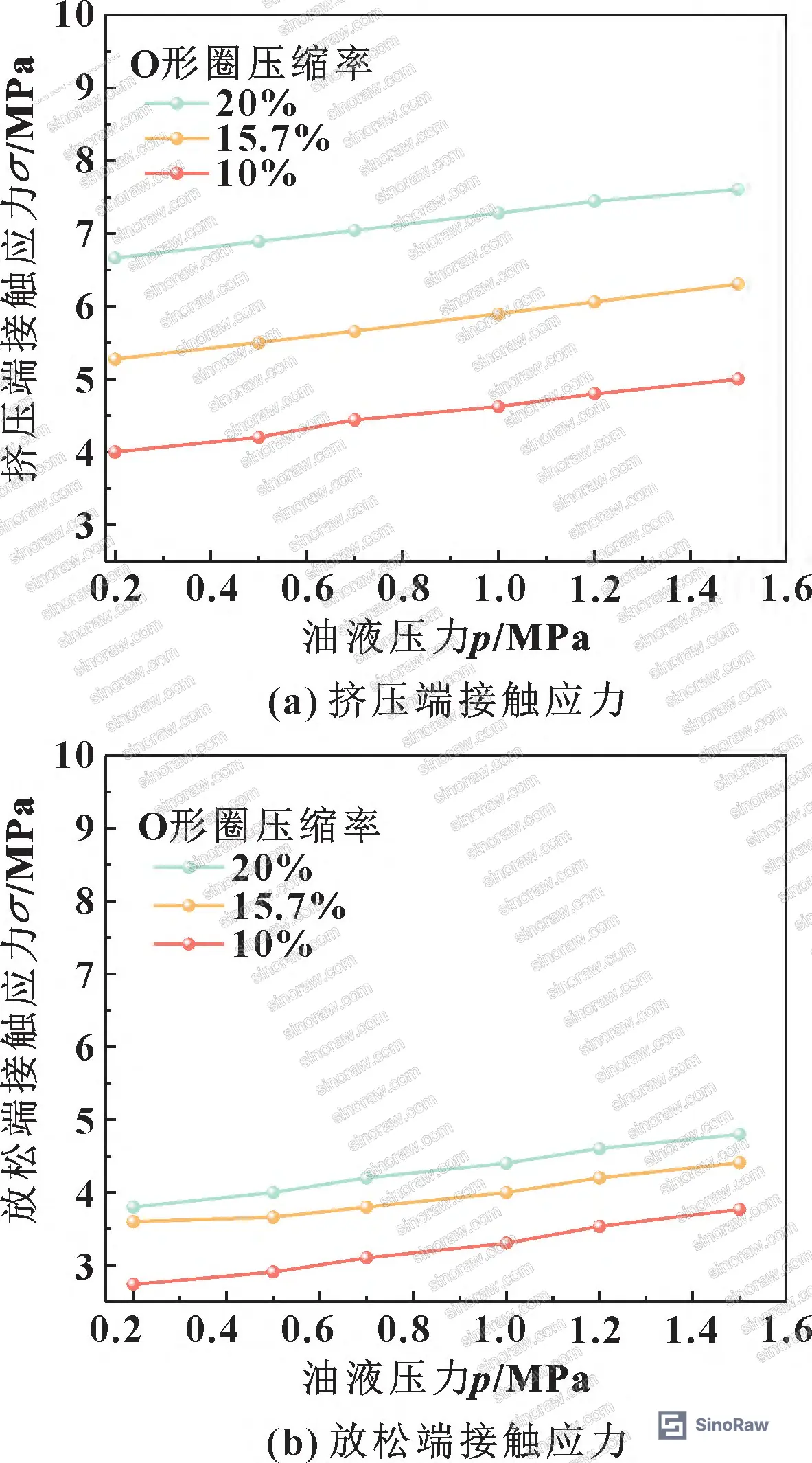
Positive effect: At the extrusion (compression) end of the stroke, torsion increases contact stress above the equivalent static seal value. This means the O-ring is actually sealing harder at that face than a static seal of the same compression ratio would.
Negative effect: At the relaxation end, contact stress drops below the static seal equivalent. This is the leak path. The asymmetry between extrusion-end and relaxation-end contact stress is why dynamic seal leakage rates are consistently higher than static seal leakage rates at the same compression ratio.
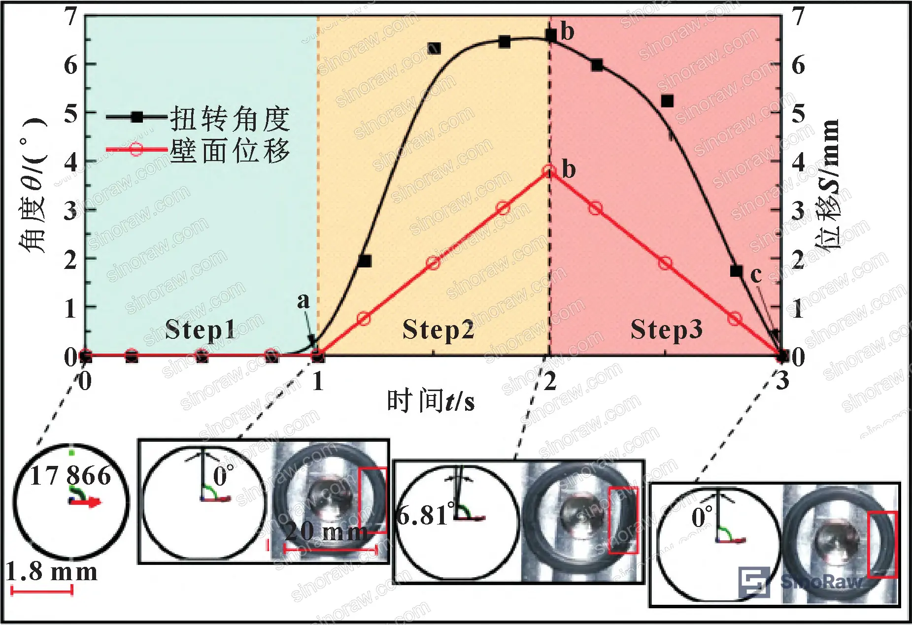
The experimental results confirm this directly. Across all four compression ratios tested at 0–1.5 MPa, dynamic seal leakage rates exceeded static seal leakage rates at equivalent compression and pressure conditions. However — and this is the critical procurement insight — at higher oil pressures within the 0–1.5 MPa range, high-compression-ratio O-rings showed markedly better dynamic sealing performance than low-compression-ratio O-rings. The performance gap between compression ratios widens as pressure increases.
In supplier qualification, we’ve seen situations where three of six O-ring samples from a single batch failed dynamic leakage criteria at 1.0 MPa despite passing static leakage tests at the same pressure. The root cause in each case traced back to insufficient compression ratio — the supplier had sized the groove for a nominal 10% compression when the application required 18–20% to maintain adequate contact stress at the relaxation end during reciprocation.
There is also a long-term risk that the research explicitly flags: the torsion phenomenon that enhances dynamic sealing also increases the risk of O-ring cracking over service life. High-compression dynamic seals seal better in the short term but accumulate more fatigue damage per cycle. This is a maintenance interval consideration, not just a specification issue.
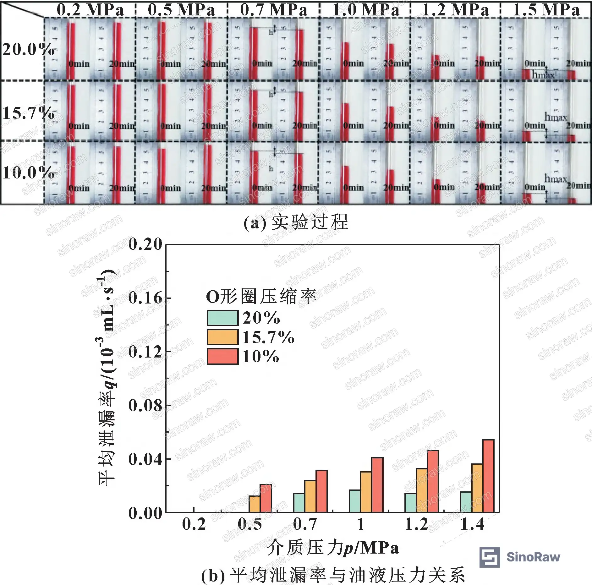
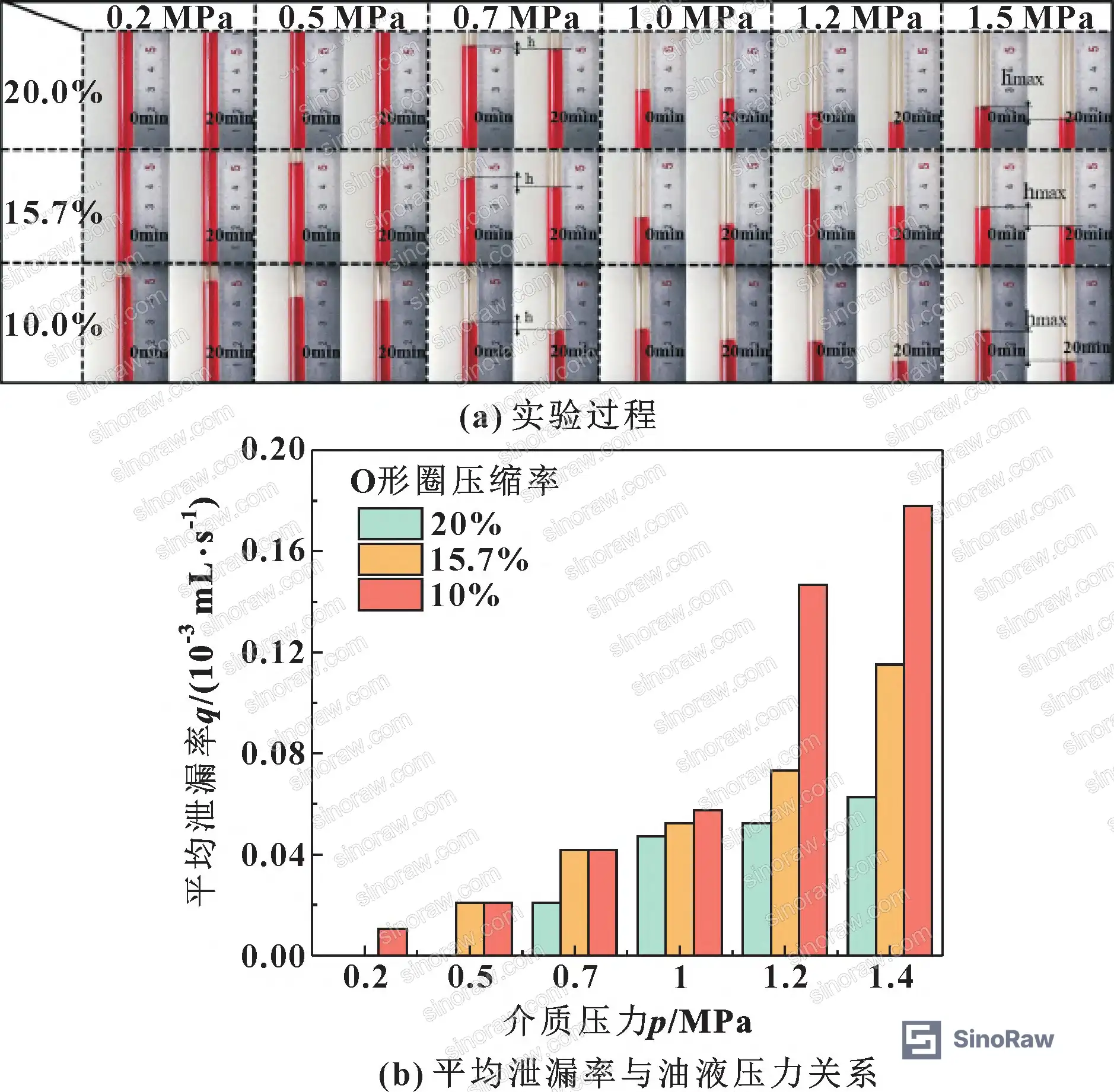
Most procurement teams don’t realize that the distinction between static and dynamic seal performance is rarely captured in standard supplier qualification documents. A supplier can pass a static leakage test at 1.5 MPa and still deliver a product that leaks unacceptably in a reciprocating actuator at 0.8 MPa. The test conditions must match the application mode.
For buyers working with hydraulic systems that cycle between low and high pressure states, the ISO 12405-4 Electrically propelled road vehicles — Test specification for lithium-ion traction battery packs and systems standard offers a useful parallel for understanding how alternating-load test protocols are structured — the same principle of cycling between boundary conditions applies to hydraulic seal qualification under variable pressure.
Practical Guidance for Buyers #
When you’re evaluating Chinese O-ring suppliers for hydraulic pump or valve actuator applications, the first question is not “what material?” — NBR is the standard for most hydraulic oil environments. The real questions are about compression ratio, groove geometry, and whether the supplier has tested under the actual seal mode your application requires.
For static seal applications in the 0–1.5 MPa range, the data supports specifying compression ratios in the upper portion of the standard range. For dynamic (reciprocating) applications, you need to go higher — and you need leakage rate data from a dynamic test bench, not just a static compression test. The groove dimensions matter too: the 20 mm inner diameter, 3.6 mm wire diameter, 4 mm groove width, and 3 mm groove depth geometry used in this evaluation represents a well-characterized reference point for actuator-grade seals.
At sinoraw.com, our sourcing team works specifically with overseas procurement engineers and quality managers to identify and pre-qualify Chinese seal manufacturers — connecting buyers with verified suppliers before RFQs are issued, so you’re not discovering compression ratio problems after the first production run. If your application involves alternating static and dynamic seal conditions, make sure your supplier can provide both static and dynamic leakage rate data at your target pressure. Don’t accept a static test result as a proxy for dynamic performance.
For related sealing component categories, see our Sealing & Thermal documentation for additional material and specification guidance.
The GB/T 36276-2018 Lithium-ion batteries for electrical energy storage standard, while specific to energy storage, illustrates how Chinese national standards structure performance verification requirements — a useful reference when reviewing Chinese supplier test documentation formats.
Need help identifying qualified suppliers for NBR O-rings and hydraulic actuator seals? Talk to our sourcing team →
Supplier Qualification Questions #
- What compression ratios do you offer for your NBR O-ring groove designs, and can you provide FEA contact stress data showing that the primary sealing face contact stress exceeds the rated oil pressure across the 0–1.5 MPa operating range?
- Do you have dynamic (reciprocating) leakage rate test data for your O-rings, and can you show the average leakage rate vs. oil pressure curve for at least two different compression ratios under dynamic seal conditions?
- What Mooney-Rivlin material constants (C10 and C01) do you use for your NBR compound, and how do these correspond to the elastic modulus of 14.04 MPa and Poisson’s ratio of 0.499 used in standard hyperelastic characterization?
- For dynamic seal applications, can you demonstrate that your O-ring maintains adequate contact stress at the relaxation end of the reciprocating stroke — specifically that relaxation-end contact stress does not fall below the applied fluid pressure at your rated operating pressure?
- What is your groove geometry specification (inner diameter, wire diameter, groove width, groove depth) for your standard actuator-grade O-ring, and how does your compression ratio calculation account for groove depth tolerance variation across production batches?
Sourcing Checklist #
- Supplier provides NBR O-ring with confirmed elastic modulus of 14.04 MPa (±10%) and Poisson’s ratio of 0.499, verified by material test certificate or Mooney-Rivlin curve data
- Static seal leakage rate test data available for pressure range 0–1.5 MPa, showing decreasing leakage trend with increasing oil pressure across at least two compression ratios
- Dynamic (reciprocating) seal leakage rate test data available, confirming that high-compression-ratio O-rings outperform low-compression-ratio O-rings at oil pressures above 0.8 MPa
- Groove geometry dimensions confirmed: wire diameter 3.6 mm, groove width 4 mm, groove depth 3 mm (or equivalent documented design with compression ratio calculation)
- FEA simulation report or contact stress test data showing that primary sealing face (wall-contact surface) contact stress exceeds applied fluid pressure at rated operating conditions
- Supplier can confirm compression ratio for each supplied O-ring size and has documented the relationship between compression ratio and contact stress for their specific NBR compound
- Supplier acknowledges the torsion-cracking risk in dynamic seal applications and can provide recommended maintenance interval or fatigue life data for high-compression-ratio dynamic seals
- Test bench validation method documented: leakage rate measured via fluid level change in sealed tube, contact pressure recorded via sensor, and reciprocating wall motion confirmed as part of dynamic test protocol
Key Specifications Table #
| Parameter | Recommended Value | Verification Method |
|---|---|---|
| NBR O-ring elastic modulus | 14.04 MPa | Material test certificate; Mooney-Rivlin curve fitting |
| NBR Poisson’s ratio | 0.499 (near-incompressible) | Hyperelastic constitutive model validation |
| O-ring wire diameter (actuator-grade reference) | 3.6 mm | Dimensional inspection per batch |
| Groove depth (reference geometry) | 3 mm | Groove gauge measurement |
| Groove width (reference geometry) | 4 mm | Groove gauge measurement |
| Operating pressure range (low-pressure regime) | 0–1.5 MPa | Leakage rate test bench at rated pressure steps |
| Compression ratio (static seal, low-pressure) | ≥15% recommended | Calculated from groove depth and wire diameter; confirmed by contact stress data |
| Compression ratio (dynamic/reciprocating seal) | ≥18–20% recommended | Dynamic leakage rate test at 0–1.5 MPa with reciprocating wall motion |
| FEA mesh convergence threshold | Error ≤10% above 40,000 elements | Grid independence study documentation |
| Sealing wall material (reference) | 45 steel, E = 2.1×10⁵ MPa | Material certificate |
Can’t find a supplier meeting these specs? Submit your requirements and we’ll match you within 48 hours.
References #
Data source: Sealing Performance of Nitrile Rubber O-Rings Under Low-Pressure Dynamic and Static Conditions: Finite Element Analysis and Experimental Validation, B. Zeng et al., Tribology International, 2024
Frequently Asked Questions #
Why does leakage rate decrease as oil pressure increases in static seal tests?
This seems counterintuitive, but it’s consistent with the sealing mechanism. As oil pressure increases, the fluid itself pushes the O-ring harder against the primary sealing wall, increasing contact stress at that interface. As long as the contact stress exceeds the fluid pressure — which it does when compression ratio is adequate — the seal actually tightens under pressure. The leakage rate drops because the contact stress margin grows.
What is the torsion phenomenon in dynamic O-ring seals, and why does it matter for procurement?
During reciprocating motion, the O-ring rolls and twists rather than sliding cleanly. The side of the O-ring in the direction of wall motion gets compressed first, while the opposite side relaxes. This creates an asymmetric contact stress distribution: the extrusion end seals harder than a static seal, but the relaxation end seals softer. The net result is higher leakage than static sealing at the same compression ratio. For procurement, this means you cannot use static leakage test results to qualify an O-ring for a dynamic application.
Is NBR the right material for all low-pressure hydraulic seal applications?
NBR (nitrile rubber) is the standard choice for most mineral oil hydraulic systems and covers the majority of industrial pump and valve actuator applications. Its elastic modulus of approximately 14 MPa and near-incompressible behavior (Poisson’s ratio ~0.499) make it well-suited for the hyperelastic deformation required in O-ring sealing. However, for applications involving phosphate ester fluids, high-temperature environments above 120°C, or aggressive chemical exposure, alternative elastomers such as FKM (Viton) should be evaluated.
How do I specify compression ratio when ordering O-rings from a Chinese supplier?
Compression ratio is determined by the relationship between the O-ring wire diameter and the groove depth: compression ratio = (wire diameter − groove depth) / wire diameter × 100%. For the reference geometry in this evaluation (wire diameter 3.6 mm, groove depth 3 mm), the compression ratio is approximately 16.7%. When ordering, specify both the O-ring wire diameter and the groove depth tolerance — not just the O-ring dimensions — so the supplier can confirm the installed compression ratio in your specific housing.
Does the torsion-enhanced sealing in dynamic applications mean I should always use the highest possible compression ratio?
No — and this is a common over-specification mistake. Higher compression ratios do improve dynamic sealing performance at elevated pressures within the low-pressure range, but the same torsion mechanism that increases contact stress also accelerates fatigue damage and increases the risk of O-ring cracking over service life. There is a practical upper limit, typically around 25–30% for most NBR compounds, beyond which extrusion risk and fatigue damage outweigh the sealing benefit. Match compression ratio to your actual operating pressure and cycle frequency, not to the maximum the groove geometry can accommodate.
Published by sinoraw.com Technical Team | Request a sourcing quote


