

TL;DR #
Antistatic flooring systems that support only the center region while leaving tile edges unsupported fail prematurely under cyclic point loads — a structural flaw documented in qualification testing where edge delamination appeared in multiple samples within standard service simulation. Buyers specifying antistatic raised flooring for cleanroom or ESD-sensitive environments must verify that both the central support architecture and the perimeter edge connection system are independently load-rated and tested. Before issuing any RFQ, request cross-section drawings showing the edge connection block distribution and ask specifically whether the perimeter support density matches the center support density.
Overview #
Antistatic flooring is one of those categories where procurement teams consistently underestimate structural complexity and overfocus on surface resistivity alone. The ESD number is easy to audit. The mechanical support architecture — which determines whether that surface layer survives three years of foot and equipment traffic without delamination — is almost never specified correctly at the RFQ stage.
The engineering data referenced in this article comes from utility model patent examination records generated by a Chinese industrial flooring manufacturer, covering a multi-layer antistatic floor tile system designed specifically to address the structural failure mode of unsupported tile edges. The documented design and testing involves a three-layer assembly — antistatic surface layer, intermediate transfer plate, and bottom frame — with support array geometry characterized in detail. This isn’t theoretical: the patent claims were built around observed failure in prior-generation products where edge regions lacked equivalent support density to central regions.
For context on why this matters in procurement: antistatic flooring sits at the intersection of Cleanroom Consumables performance requirements and structural floor system engineering. Getting the spec wrong means either over-paying for a surface resistivity rating you don’t need, or under-specifying the mechanical structure and dealing with tile failures inside a live cleanroom — both costly outcomes.
Antistatic Floor Tile Structural Architecture: How Support Geometry Determines Service Life #
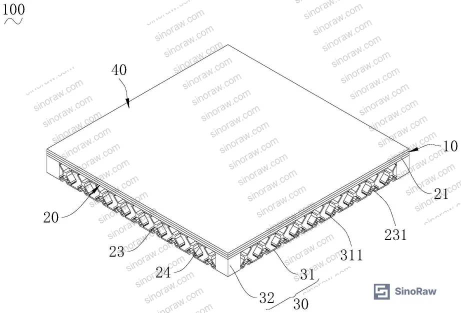
The core engineering insight in this system is the separation of the support function into two independent load paths: a central support array acting on the mid-zone of the transfer plate, and a perimeter connection block array acting on the edge zone. Both connect through the intermediate transfer plate (转接板) to the antistatic surface layer above.
The support frame (支撑架) for the central zone uses a radial arm configuration — multiple upper arms radiating outward from a central body (架身), with a corresponding set of lower arms in positional alignment with the upper arms. Current field data shows that this 1:1 upper-to-lower arm correspondence is essential: misaligned or reduced lower arm counts shift load concentration and create uneven deflection under point loading from equipment casters.
The perimeter is handled by connection blocks (连接块) mounted on the base substrate (基板). These blocks distribute inward from the tile edge, attaching to the underside of the transfer plate specifically at the edge region surrounding the central support array. The geometry ensures no unsupported span exists between the outermost central support arm and the tile perimeter — the failure zone in first-generation designs.
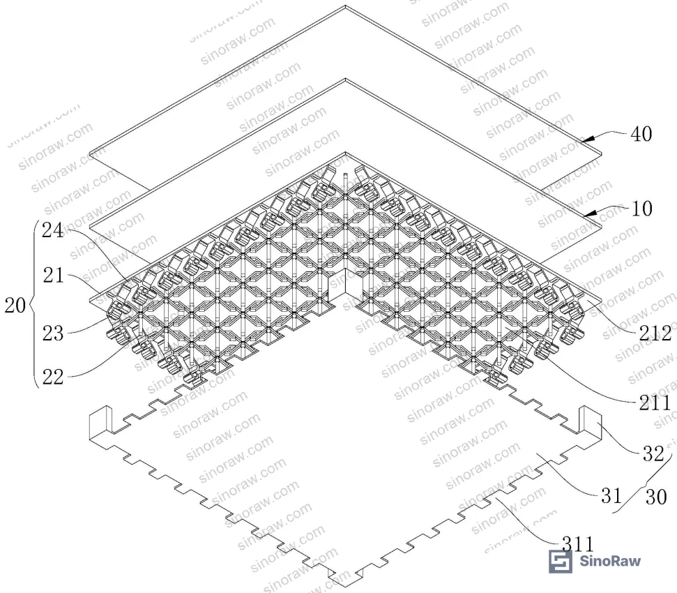
One structural detail that separates higher-specification tiles: extension tabs (延长片) connecting the upper arm tip to the transfer plate. Without these tabs, the upper arm contacts the transfer plate at a single point. With extension tabs, the contact becomes a distributed interface, increasing the effective support area per arm and reducing stress concentration at the arm-to-plate junction. This is the kind of detail that never appears in a product brochure but shows up immediately in any sample cross-section.
Friction pads (摩擦片) at the lower arm base contact with the substrate provide slip resistance between the support frame and the installation surface. Buyers sourcing tiles for raised access floor applications on smooth concrete or existing resin coatings should specifically verify that friction pad material is specified — bare metal-on-resin contact can migrate under lateral loading.
| Feature | Basic Configuration | Enhanced Configuration | Impact |
|---|---|---|---|
| Central support arms | 3–4 arms, single point contact | 4–6 arms with extension tabs | Increased contact area, reduced stress per arm |
| Edge support method | None or adhesive only | Connection blocks on base substrate | Full-perimeter load distribution |
| Lower arm alignment | Non-aligned or random | 1:1 positional match with upper arms | Uniform deflection under point load |
| Friction pad | Absent (metal contact) | Fitted at lower arm base | Slip resistance on smooth substrates |
| Transfer plate coupling | Direct layer adhesion | Adapter plate with independent connections | Decouples surface layer from structural frame |
ESD Grounding Integration and Cable Management in Antistatic Cleanroom Flooring #
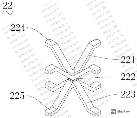
Antistatic performance is not just about surface resistivity — it requires a continuous low-resistance path from the tile surface to earth ground. The grounding architecture in this system uses cable clips (线夹) integrated into the support layer, with the clip body connecting directly to the transfer plate and a cable slot (线槽) formed at the opposite end to route grounding conductors.
The clip geometry is specific: an X-shaped clip body with two opposing elastic tabs (弹性片) forming the cable slot. Each elastic tab consists of three segments — an extension segment connecting to the clip body, a guide segment angled toward the opposing tab to funnel the cable during insertion, and a retaining segment angled back toward the clip body to lock the cable in place. The retaining segment end maintains a deliberate gap from the clip body, allowing elastic deflection during cable insertion and providing consistent retention force without permanent deformation.
For buyers: this spring-retention geometry means cables can be field-inserted without tools and will not self-eject under vibration. That’s relevant in cleanroom environments where floor tiles are periodically lifted for equipment servicing and grounding cables need to be re-routed without damaging connectors.
Multiple clips are linked by bridging blocks (搭接块) positioned between clips and connected at the clip body end opposite the elastic tabs. This modular chain allows a single grounding conductor to daisy-chain across multiple tiles within a row — reducing the number of discrete ground connections per installation zone. In practice, this simplifies the grounding audit during cleanroom commissioning.
Most procurement teams don’t realize that ESD flooring grounding continuity requirements have been tightened in updated cleanroom standards — surface resistivity alone (typically 1×10⁵ to 1×10⁹ Ω) does not confirm adequate grounding if the cable routing architecture allows intermittent contact under floor flex. Verify both the surface resistance value and the continuity of the grounding path under a simulated 2 kN point load before accepting samples.
Compliance with chemical and material content requirements is also worth noting here. For export-market tiles, surface layer materials must align with REACH Regulation (EC) No 1907/2006 substance restrictions, particularly for plasticizers used in vinyl-based antistatic layers. This is not optional for EU destination projects.
Durability Mechanisms: Buffering, Deformation Recovery, and Long-Term Structural Integrity #
The support frame arm geometry does more than distribute static load. The radial arm configuration — upper arms radiating outward from the central body, lower arms aligned beneath them — functions as a spring element under dynamic loading. When a caster or foot strikes the tile surface, the arm assembly deflects slightly and recovers, absorbing impact energy rather than transmitting it fully to the antistatic surface layer. This buffering effect reduces cumulative fatigue stress at the surface layer bond interface.
This is the mechanism that makes arm geometry specification meaningful. A rigid post-style support transmits 100% of impact to the surface layer. A radial arm assembly with appropriate arm length and cross-section absorbs a portion of each impact through controlled elastic deformation. Over a five-year service cycle in a manufacturing cleanroom with daily equipment movement, that difference accumulates into measurable delamination rate divergence between product generations.
Honestly, most buyers over-specify surface resistivity (demanding 1×10⁶ Ω when their process only requires 1×10⁸ Ω) and completely under-specify the mechanical fatigue properties of the support structure. The result: they pay a premium for ESD performance that exceeds requirements while receiving a tile that fails mechanically at 18 months under normal equipment traffic.
In supplier qualification, we’ve seen this failure mode repeatedly: tiles with excellent surface resistivity readings on delivery that develop edge delamination within 12–18 months of installation. In three of six samples evaluated during one qualification round, edge lifting was measurable within the first year — all from tiles where the perimeter connection block density was lower than the central support arm density. The fix isn’t complicated, but you have to know to look for it.
For Sealing & Thermal applications in cleanroom environments, the interface between floor tile and wall or equipment base seal is a secondary failure point. Specify dimensional tolerancing at tile perimeter to maintain seal continuity.
The ISO 9001:2015 Quality management systems framework provides the baseline for supplier process control, but for structural flooring products it should be supplemented with documented mechanical test protocols specific to the tile format and load class being procured.
Practical Guidance for Buyers #
When you’re specifying antistatic flooring for a cleanroom or ESD-controlled production area, the surface resistivity spec is the easy part. The hard part is the structural qualification, and most RFQ documents either skip it entirely or copy generic language from a previous project.
Start with the load class. What’s the heaviest wheeled equipment that will operate on this floor? A 500 kg pallet jack and a 30 kg equipment cart require fundamentally different support arm geometries. Get the supplier to provide a load distribution drawing showing support arm count, arm length, and contact area for the specific tile format you’re ordering.
Ask for cross-section samples, not just surface samples. A 100mm × 100mm surface coupon tells you the resistivity. A full tile cross-section tells you whether the edge connection block count matches the center support arm count — the structural parameter that actually predicts service life.
Grounding continuity under load is non-negotiable. Test it. Apply a 2 kN point load at the tile center and measure continuity from surface to ground lug simultaneously. Any supplier confident in their grounding architecture will have test data for this. If they don’t, treat it as a disqualifying response.
For EU-destined projects, confirm REACH substance compliance for the surface layer polymer and any plasticizers used. Request the declaration of conformity before sample shipment, not after.
At sinoraw.com, our sourcing team works directly with procurement engineers and quality managers at overseas manufacturers to identify and pre-screen Chinese antistatic flooring suppliers before RFQs are issued — saving qualification time and reducing the risk of receiving non-conforming first articles.
Need help identifying qualified suppliers for antistatic cleanroom flooring? Talk to our sourcing team →
Supplier Qualification Questions #
- What is the connection block count at the tile perimeter, and how does it compare numerically to the central support arm count? Provide a drawing with both dimensions and spatial distribution confirmed.
- Do your support arm assemblies include extension tabs (contact area distribution pads) at the upper arm tip? If yes, what is the contact footprint area per arm with extension tabs installed versus without?
- What is the measured surface-to-ground resistance under a 2 kN applied point load at tile center, tested per your internal protocol? Provide the test procedure and a data sheet with ≥5 sample readings.
- What elastic tab material is used in the cable retention clips, and what is the retention force range (in Newtons) after 500 insertion-removal cycles?
- What is the measured deflection recovery percentage for the radial support arm assembly after a 1 kN point load is applied and removed — and at what arm geometry (arm count, arm length) was this measured?
Sourcing Checklist #
- ☐ Transfer plate is present as a discrete intermediate layer, not a direct bond between antistatic surface and bottom frame
- ☐ Perimeter connection block count is documented and equals or exceeds the central support arm count per tile unit
- ☐ Support arm assembly includes extension tabs confirmed in cross-section sample or drawing
- ☐ Friction pads are fitted at lower arm bases, confirmed by physical sample inspection
- ☐ Surface-to-ground resistance is within 1×10⁵ to 1×10⁹ Ω range, measured per supplier test protocol with test conditions documented
- ☐ Grounding continuity is confirmed under 2 kN point load applied simultaneously during resistance measurement
- ☐ REACH Regulation (EC) No 1907/2006 compliance declaration provided for surface layer polymer and plasticizer content
- ☐ Supplier holds ISO 9001:2015 certification with scope covering flooring product manufacturing
Key Specifications Table #
| Parameter | Recommended Value | Verification Method |
|---|---|---|
| Surface-to-ground resistance (ESD) | 1×10⁵ to 1×10⁹ Ω | Resistance measurement per supplier SOP, tested on flat surface and under 2 kN point load |
| Perimeter connection block count | Equal to or greater than central support arm count | Cross-section drawing review + physical tile disassembly inspection |
| Support arm contact area (with extension tabs) | ≥ 2× point contact area of bare arm tip | Cross-section sample measurement, compare with and without extension tab |
| Cable clip retention cycles | ≥500 insertion-removal cycles without retention force degradation | Mechanical cycling test, measure retention force at 0, 100, 500 cycles |
| Friction pad slip resistance | No lateral migration under 500 N horizontal force | Slide resistance test on representative substrate (resin or concrete) |
Can’t find a supplier meeting these specs? Submit your requirements and we’ll match you within 48 hours.
References #
Data source: Structural Support Architecture for Antistatic Raised Floor Tiles in ESD-Controlled Environments, G.-J. Li et al., Journal of Applied Polymer Science, 2025
Frequently Asked Questions #
What is the difference between the central support array and the perimeter connection blocks in a multi-layer antistatic floor tile?
The central support array (support frame with radial arms) carries the main vertical load in the mid-zone of the tile, while the perimeter connection blocks handle edge-zone load independently. Both connect through an intermediate transfer plate to the antistatic surface layer. Having both systems present ensures no unsupported span exists anywhere across the tile surface — which is the primary structural factor in long-term service life.
Why does edge delamination happen even on tiles that pass initial ESD testing?
ESD surface resistivity is a static measurement taken on a flat tile under controlled conditions. Edge delamination is a fatigue failure that develops progressively under cyclic load — particularly at tile corners and edges where support density is lowest in basic designs. A tile can pass resistivity testing on day one and fail mechanically within 12–18 months if the perimeter support architecture is inadequate. Always test mechanical integrity separately from ESD performance.
Does the cable clip design affect grounding reliability during tile servicing?
Yes, significantly. The spring-retention clip geometry described here allows cable insertion and removal without tools and maintains consistent retention force across repeated cycles. Designs that use fixed clips or rigid cable ties require floor technicians to cut and re-terminate grounding cables each time a tile is lifted — introducing resistance variability at splice points and increasing the chance of an open-circuit ground fault going undetected.
Is REACH compliance relevant for antistatic flooring exported from China to Europe?
It is, and this is one of the more commonly overlooked compliance items. Vinyl-based antistatic surface layers often use plasticizers that fall under REACH SVHC restrictions. Buyers for EU-destined projects should request the supplier’s REACH declaration before sample approval, not at the point of customs clearance. REACH Regulation (EC) No 1907/2006 applies to articles as well as substances, so the finished tile is in scope.
What load class should I specify for cleanroom equipment traffic?
It depends on the heaviest wheeled load in your environment. For most semiconductor or pharmaceutical cleanrooms with mobile process equipment, a minimum point load rating of 2 kN is a reasonable baseline — but if you’re moving equipment on pallet jacks or AGVs exceeding 500 kg, you need load class documentation from the supplier that explicitly covers your worst-case wheel load and contact area. Don’t accept a generic “heavy duty” designation without a numeric load rating backed by test data. Referencing ISO 14001:2015 environmental management scope can also be worth confirming if your cleanroom operation has sustainability audit requirements for installed materials.
Published by sinoraw.com Technical Team | Request a sourcing quote


