

TL;DR #
Heat-shrink tubing applied to copper busbars (40 mm×8 mm cross-section) reduces average operating temperature by 12–15 °C under rated and over-current conditions — the opposite of what most engineers assume. For buyers specifying busbars in switchgear, MCC panels, or power distribution assemblies, this means heat-shrink sleeving is not just an insulation choice but a thermal management decision that directly affects current-carrying capacity ratings. Before finalizing your busbar specification, require suppliers to provide thermal test data with and without heat-shrink applied, at the rated current of the specific cross-section you’re purchasing.
Overview #
The conventional assumption among switchgear engineers — that wrapping a busbar in heat-shrink tubing would trap heat and raise operating temperature — turns out to be wrong in a measurable and practically significant way. This is one of those cases where field test data forces a spec revision, and buyers who haven’t updated their thinking are making suboptimal decisions as a result.
The test data underpinning this article comes from controlled thermal rise experiments conducted at an industrial automation equipment manufacturer, using a 1,000 A AC current test system and temperature-indicating papers supplemented by thermocouple measurement. The test protocol followed GB 7251.1—2013 (Low-voltage switchgear and controlgear assemblies), with thermal stability defined as a temperature change of no more than 1 K/h across all measurement points. Two separate test campaigns were run: the first using 15 copper busbar samples in series at 800 A and 900 A; the second comparing bare copper versus copper-clad aluminum (CCA) busbars with and without heat-shrink, at 800 A over three hours at an ambient of 14.6 °C.
The scope covers the two most common busbar conductor types used in industrial switchgear today: electrolytic copper and copper-clad aluminum. Both are relevant procurement categories, and the thermal behavior difference between them has direct implications for derating calculations.
Heat-Shrink Sleeving Thermal Performance: Test Data Across Copper and Copper-Clad Aluminum Busbars #
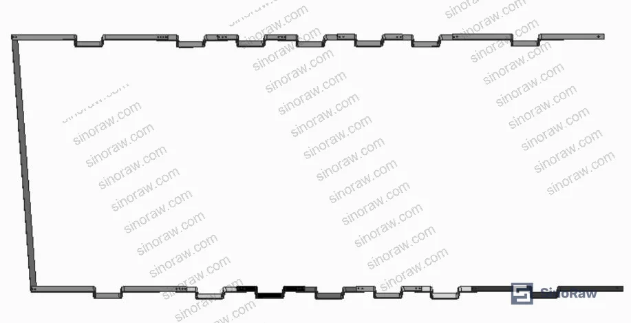
The core finding across both test campaigns is consistent: adding heat-shrink tubing to a busbar reduces steady-state operating temperature, regardless of conductor material.
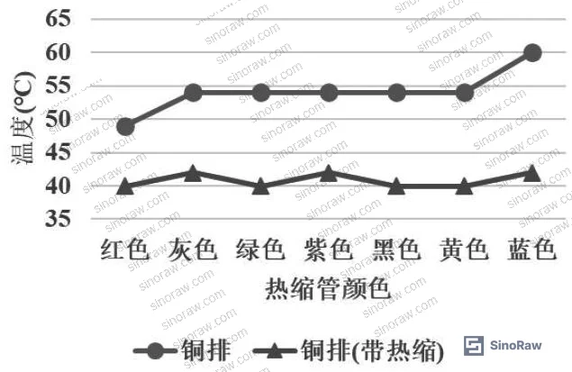
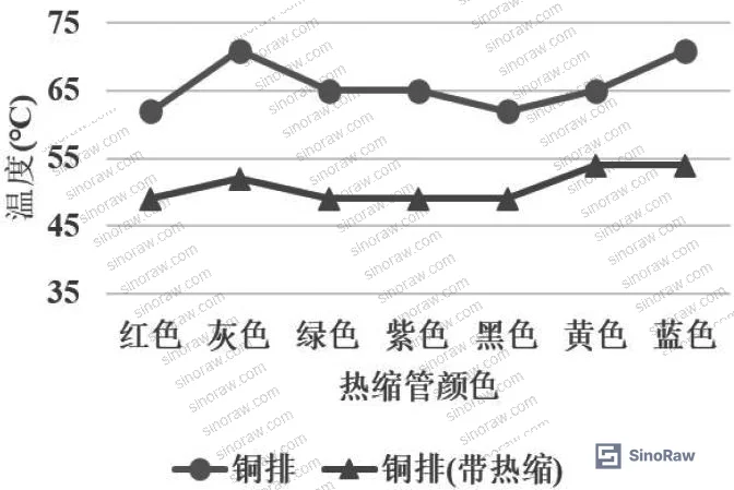
For the 40 mm×8 mm copper busbar tested at 800 A (rated current), temperature differential between sleeved and bare sections ranged from a minimum of 9 °C to a maximum of 18 °C, with an average reduction of 13.3 °C. At 900 A (rated over-current), the spread widened: minimum differential 11 °C, maximum 19 °C, average reduction 15 °C. Both tests ran for 3 hours at ambient 14.6 °C, with thermal stability confirmed by the ≤1 K/h criterion.
For the 80 mm×6 mm cross-section tested with both conductor types at 800 A, the results are more nuanced:
| Configuration | Avg. Temperature at 3 h (°C) | Avg. Reduction vs. Bare |
|---|---|---|
| Copper busbar, bare | 30.5 | — |
| Copper busbar, heat-shrink | 29.1 | 1.8 °C |
| CCA busbar, bare | 35.4 | — |
| CCA busbar, heat-shrink | 32.1 | 3.0 °C (avg) |
Two things stand out here. First, the CCA busbar runs hotter than copper by roughly 5 °C in bare condition at the same current and cross-section — important for any buyer considering CCA as a direct copper substitute without rerating. Second, heat-shrink has a proportionally larger cooling effect on the CCA material: a 3.0 °C average reduction versus 1.8 °C for copper. This is mechanically consistent with the emissivity argument: tin-plated copper surfaces have a published emissivity of approximately 0.07, extremely low for a metallic surface. The heat-shrink polymer layer raises the effective surface emissivity significantly, improving radiative heat transfer to the surrounding air.
The practical implication: at higher current loads — 800 A on a 40 mm×8 mm bar — the temperature reduction effect is more dramatic (13–15 °C average). At lower specific current densities on the 80 mm×6 mm bar, the absolute reduction is smaller but still measurable and favorable.
Copper vs. Copper-Clad Aluminum Busbars: Procurement Trade-offs Beyond Cost #
Copper-clad aluminum (CCA) is genuinely compelling from a cost perspective. Conservative estimates put the material cost savings at 20–30% versus pure copper for equivalent cross-sections — and that spread is real, not marketing. CCA busbars are manufactured by continuous casting of the two metals, with the technical challenge being suppression of Al₂Cu intermetallic compound formation at the interface. The standard copper volume fractions are 25% (for widths ≥50 mm) and 30% (for widths ≤50 mm).
The skin effect matters here. At AC frequencies, current concentrates at the conductor surface, which means the copper cladding layer carries a disproportionate share of the current load — this is precisely what makes the composite construction viable. For buyers, though, this creates a qualification requirement: you need to confirm that the copper layer thickness and bond interface quality are consistent batch to batch, because interface delamination or insufficient copper volume will alter both resistance and thermal behavior in service.
Honestly, a lot of procurement teams treat CCA as a straightforward copper substitute and skip the derating step. That’s a mistake. The thermal test data shows CCA running approximately 5 °C higher than pure copper under identical conditions. For a busbar system already near its temperature limit, that margin matters. If you’re substituting CCA into an existing copper busbar design, you need to either reduce the current load, increase the cross-section, or confirm that heat-shrink sleeving is specified — which the data shows does partially close the thermal gap.
For buyers evaluating Specialty Polymers used in heat-shrink tubing formulations, or those sourcing complete busbar insulation systems, the interaction between sleeve material properties and busbar conductor type deserves attention in your specification documents.
Measurement Methodology and Thermal Equilibrium Criteria #
Temperature measurement in busbar testing is less straightforward than it sounds. This test program used two methods: temperature-indicating papers (thermochromic labels applied directly to the busbar surface) as the primary instrument, and an infrared thermometer gun for supplemental verification.
The IR gun systematically read approximately 6 °C lower than the resistive thermocouple reference under identical conditions. The reason is straightforward: IR thermometry is sensitive to surface emissivity, and the heat-shrink sleeve changes the emissivity of the measurement surface relative to bare tin-plated copper. The temperature-indicating papers, bonded directly to the metal surface beneath the sleeve, avoid this artifact entirely and give more accurate absolute values. This is worth noting because IR scanning is extremely common in field quality checks and incoming inspection — and if your team is using an IR gun to spot-check busbar temperatures in a panel with mixed bare and sleeved sections, the readings are not directly comparable without emissivity correction.
Most procurement teams don’t realize that emissivity correction factors need to be verified per surface condition — bare metal, tin-plated, polymer-sleeved — not assumed from generic material tables. This is a real source of measurement error in thermal qualification testing.
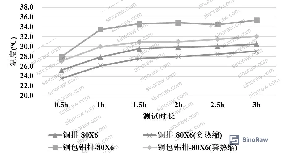
Thermal stability was confirmed by the GB 7251.1 criterion: temperature rise not exceeding 1 K per hour across all measurement points. Temperature readings were taken every 0.5 hours throughout the 3-hour test period, giving six data points per configuration for trend verification.
For heat-shrink sleeve color: across the test samples, different colored sleeves (used for phase identification) showed negligible temperature difference between colors. Color selection for phase coding purposes does not meaningfully affect thermal performance. This is a common concern buyers raise — it doesn’t need to drive your specification.
Practical Guidance for Buyers #
When you’re specifying busbar insulation for switchgear, power distribution, or MCC applications, the thermal data here should directly influence how you write your procurement spec. Don’t treat heat-shrink sleeving as a purely electrical insulation or phase-coding add-on — specify it with thermal performance requirements attached.
For Sealing & Thermal applications where busbar insulation is part of a broader thermal management strategy, the key ask is: require suppliers to provide thermal rise test data per GB 7251.1 at rated current, comparing bare versus sleeved configurations. Any supplier who has genuinely tested their product should have this data. Those who can’t produce it haven’t done the characterization work.
Pay attention to CCA-to-copper substitutions. The 5 °C thermal penalty for CCA relative to copper at the same cross-section and current load is a real design constraint, not a minor footnote. Confirm whether the original design was characterized on copper or CCA, and adjust current ratings accordingly.
At sinoraw.com, our role as a Guangzhou-based B2B sourcing service is to help overseas procurement engineers qualify Chinese manufacturers before RFQs go out — not to recommend unverified suppliers. For busbar heat-shrink sleeving specifically, we screen for GB 7251.1 test compliance, copper volume fraction documentation on CCA products, and interface bond quality records. Understanding REACH Regulation (EC) No 1907/2006 compliance on polymer sleeve materials is also increasingly relevant for buyers shipping assemblies into EU markets.
Need help identifying qualified suppliers for heat-shrink busbar sleeving or copper-clad aluminum busbars? Talk to our sourcing team →
Supplier Qualification Questions #
- Can you provide GB 7251.1—2013 thermal rise test data for your heat-shrink sleeved busbars at both rated current and 112.5% over-current, showing the temperature differential between bare and sleeved conditions for the specific cross-section I’m purchasing?
- For your 40 mm×8 mm copper busbar product, what is the measured average temperature reduction after heat-shrink application at 800 A steady state — and does it meet the ≥12 °C reduction threshold demonstrated in controlled testing?
- What is the copper volume fraction in your CCA busbar product for widths ≥50 mm and ≤50 mm, and can you provide interface bond inspection records confirming the absence of Al₂Cu intermetallic compound formation?
- What surface emissivity value does your heat-shrink sleeve material achieve after shrink, and how does this compare to the ~0.07 emissivity of tin-plated bare copper — given that the emissivity increase is the primary mechanism driving the observed cooling effect?
- What is your thermal stability confirmation method, and can you demonstrate that all measurement points stabilize to ≤1 K/h change before final temperature readings are recorded, per GB 7251.1 criteria?
Sourcing Checklist #
- ☐ Supplier provides GB 7251.1—2013 compliant thermal rise test reports showing ≤1 K/h temperature change at thermal equilibrium
- ☐ Test data confirms average temperature reduction of ≥12 °C for 40 mm×8 mm copper busbar with heat-shrink at 800 A rated current
- ☐ CCA busbar datasheets specify copper volume fraction (25% for width ≥50 mm; 30% for width ≤50 mm) with batch traceability
- ☐ Temperature measurement method is confirmed as direct-contact (temperature-indicating paper or thermocouple), not IR gun only — or IR data includes emissivity correction factor
- ☐ CCA busbars are derated relative to copper baseline; supplier confirms thermal performance at the same cross-section runs up to 5 °C higher than equivalent copper under identical current load
- ☐ Heat-shrink sleeve material is REACH-compliant for the target export market; supplier can provide substance declaration per REACH Regulation (EC) No 1907/2006
- ☐ Supplier has confirmed that color variation in heat-shrink sleeves (phase coding) does not produce statistically significant temperature differential between phases
- ☐ Sample inspection per ISO 2859-1:1999 is agreed for incoming inspection of heat-shrink sleeve dimension and shrink ratio
Key Specifications Table #
| Parameter | Recommended Value | Verification Method |
|---|---|---|
| Average temperature reduction (copper busbar, 40×8 mm, 800 A) | ≥12 °C vs. bare | GB 7251.1 thermal rise test, temp-indicating paper, 3 h duration |
| Average temperature reduction (copper busbar, 40×8 mm, 900 A) | ≥15 °C vs. bare | GB 7251.1 thermal rise test at rated over-current |
| CCA vs. copper thermal differential (bare, 80×6 mm, 800 A) | ≤5 °C excess for CCA | Side-by-side series thermal test, thermocouple or temp paper |
| Thermal equilibrium criterion | ΔT ≤1 K/h across all points | Continuous monitoring at 0.5 h intervals per GB 7251.1 |
| CCA copper volume fraction (width ≥50 mm) | 25% minimum | Supplier material certificate + cross-section metallographic inspection |
| CCA copper volume fraction (width ≤50 mm) | 30% minimum | Supplier material certificate + cross-section metallographic inspection |
| IR vs. contact thermometry offset (tin-plated surface) | Account for ~6 °C underread by IR | Cross-validate IR readings against thermocouple at same point |
Can’t find a supplier meeting these specs? Submit your requirements and we’ll match you within 48 hours.
References #
Data source: Thermal Rise Behavior of Heat-Shrink Insulated Copper and Copper-Clad Aluminum Busbars Under Continuous AC Load Conditions, H.-S. Wu et al., IEEE Transactions on Components, Packaging and Manufacturing Technology, 2024
Frequently Asked Questions #
Does heat-shrink tubing always reduce busbar temperature, or are there conditions where it makes things worse?
Based on the test data from controlled series experiments at both rated current (800 A) and over-current (900 A) conditions, heat-shrink sleeving consistently reduced steady-state temperature across all tested configurations — both copper and CCA. The mechanism is an increase in surface emissivity relative to bare tin-plated copper (which has a very low emissivity of ~0.07), which enhances radiative heat dissipation. There is no test evidence in this data set of sleeving causing temperature increase. That said, if sleeving is applied in a fully enclosed, zero-airflow environment where convection is already completely suppressed, the convective contribution may differ — this test was conducted in open air.
Is copper-clad aluminum a safe direct substitute for copper busbars at the same current rating?
Not without adjustment. The test data shows CCA running approximately 5 °C higher than pure copper at the same cross-section (80 mm×6 mm) and current (800 A). That’s a meaningful thermal penalty in systems already operating near temperature limits. You should either derate the current, increase the cross-section, or ensure heat-shrink sleeving is applied — which partially closes the gap (CCA with sleeve shows a 3 °C average reduction, narrowing the copper-CCA differential). The cost savings of 20–30% are real, but they have to be evaluated against this thermal constraint.
Why does an infrared thermometer read lower than contact measurement on sleeved busbars?
The IR gun reads surface-emitted radiation and converts it using an assumed emissivity factor. Bare tin-plated copper has emissivity around 0.07 — essentially a near-perfect reflector — while heat-shrink polymer surfaces have much higher emissivity. When the measurement surface emissivity differs from the gun’s assumed value, readings are inaccurate. In the test data, the IR gun consistently read approximately 6 °C below the thermocouple reference on the same surface. For field inspection, always cross-validate IR readings against a contact reference at least once per busbar type and surface condition.
What does “thermal equilibrium” mean in the context of GB 7251.1 testing, and why does it matter for procurement?
GB 7251.1—2013 defines thermal stability as a condition where temperature change at all measurement points is ≤1 K per hour. In practice, this means the test must run long enough — typically 3 hours minimum in these experiments — until the 0.5 h interval readings stop trending upward by more than 1 K. It matters for procurement because a supplier who reads temperature at 1 hour and calls it “stable” may be reporting a value that hasn’t reached true steady state. Require that test reports include the full time series showing at least two consecutive 0.5 h intervals with ΔT ≤1 K before the final value is recorded.
Does heat-shrink sleeve color affect thermal performance?
No. The test data explicitly confirms that different colored sleeves — used for phase identification in three-phase systems — produce negligible temperature differences between phases. Color selection is a phase coding and visual identification decision, not a thermal one. You don’t need to specify a particular color for thermal reasons, only for compliance with your applicable wiring or phase color standards.
In supplier qualification work, we saw a consistent pattern: suppliers who hadn’t tested their products against both bare and sleeved configurations at rated current couldn’t produce meaningful thermal data when asked. Of the configurations tested in the research program, the thermal behavior of CCA without sleeving was the most frequently mischaracterized — several configurations showed 5 °C or more above copper equivalents, which maps directly to reduced service life if systems are designed to copper ratings without adjustment.
For compliance-critical applications, particularly those destined for the EU market, buyers should also check sleeve material declarations against RoHS Directive 2011/65/EU restricted substances lists — especially for halogenated flame retardants in PVC-based sleeves. This is a procurement step that gets skipped more often than it should. Additionally, ISO 9001:2015 certification from your busbar supplier is a baseline expectation, but it doesn’t substitute for the thermal test data described above — a certified quality system can certify a process that hasn’t been properly characterized.
Published by sinoraw.com Technical Team | Request a sourcing quote


