

TL;DR #
Adding a cooling module to a high-speed magnetic fluid rotary seal cuts pole-shoe temperature by 31°C and raises pressure resistance by 33% — the single most decisive factor separating adequate seals from those that survive sustained high-speed operation. For buyers specifying rotary seals for gas turbine or high-speed shaft applications above 4,000 r/min, ignoring thermal management in the seal design is a specification error that will cost you during commissioning. Require documented cooling-module test data at the target shaft speed before approving any supplier sample.
Overview #
Most procurement teams evaluating rotary seals for high-speed rotating equipment default to labyrinth or brush seal designs without seriously considering magnetic fluid seals — and that’s a mistake that leaves real sealing performance on the table. The research underlying this article was conducted at a mechanical engineering institution with collaborative input from one of China’s top-tier university research centers, using a purpose-built high-speed test bench that evaluated four candidate ester-based magnetic fluids, finite element magnetic field simulation across four gap sizes (0.05, 0.1, 0.15, and 0.2 mm), and live pressure-resistance testing through shaft speeds up to 8,500 r/min. This is bench-validated data, not theoretical modeling.
The application context is gas turbine main-channel sealing — a notoriously demanding environment where shaft linear speeds can exceed 17 m/s and where conventional seals consistently show measurable leakage. Magnetic fluid seals achieve media leakage rates below 1×10⁻¹¹ Pa·m³/s, which meets the “zero leakage” threshold defined by helium mass spectrometer leak detection. That performance level puts them in a completely different category from labyrinth designs.
For buyers working in Sealing & Thermal applications or sourcing components for Pump & Valve Seals, understanding the structural variables that control magnetic fluid seal performance — gap geometry, pole tooth configuration, magnetic fluid selection, and thermal management — is the difference between a seal that lasts and one that fails at the first thermal spike.
Magnetic Fluid Properties and High-Speed Rotary Seal Design #
Selecting the right magnetic fluid is where most Chinese suppliers cut corners, and buyers rarely catch it until field failure.
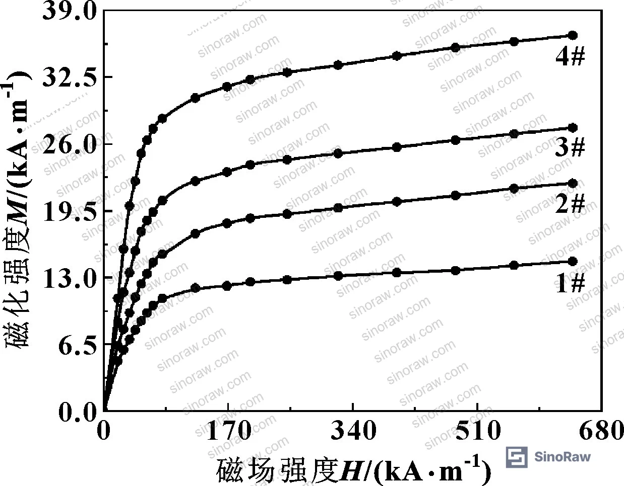
Four ester-based magnetic fluids were characterized for this evaluation. Their key properties are compared below.
| Parameter | Fluid 1# | Fluid 2# | Fluid 3# | Fluid 4# |
|---|---|---|---|---|
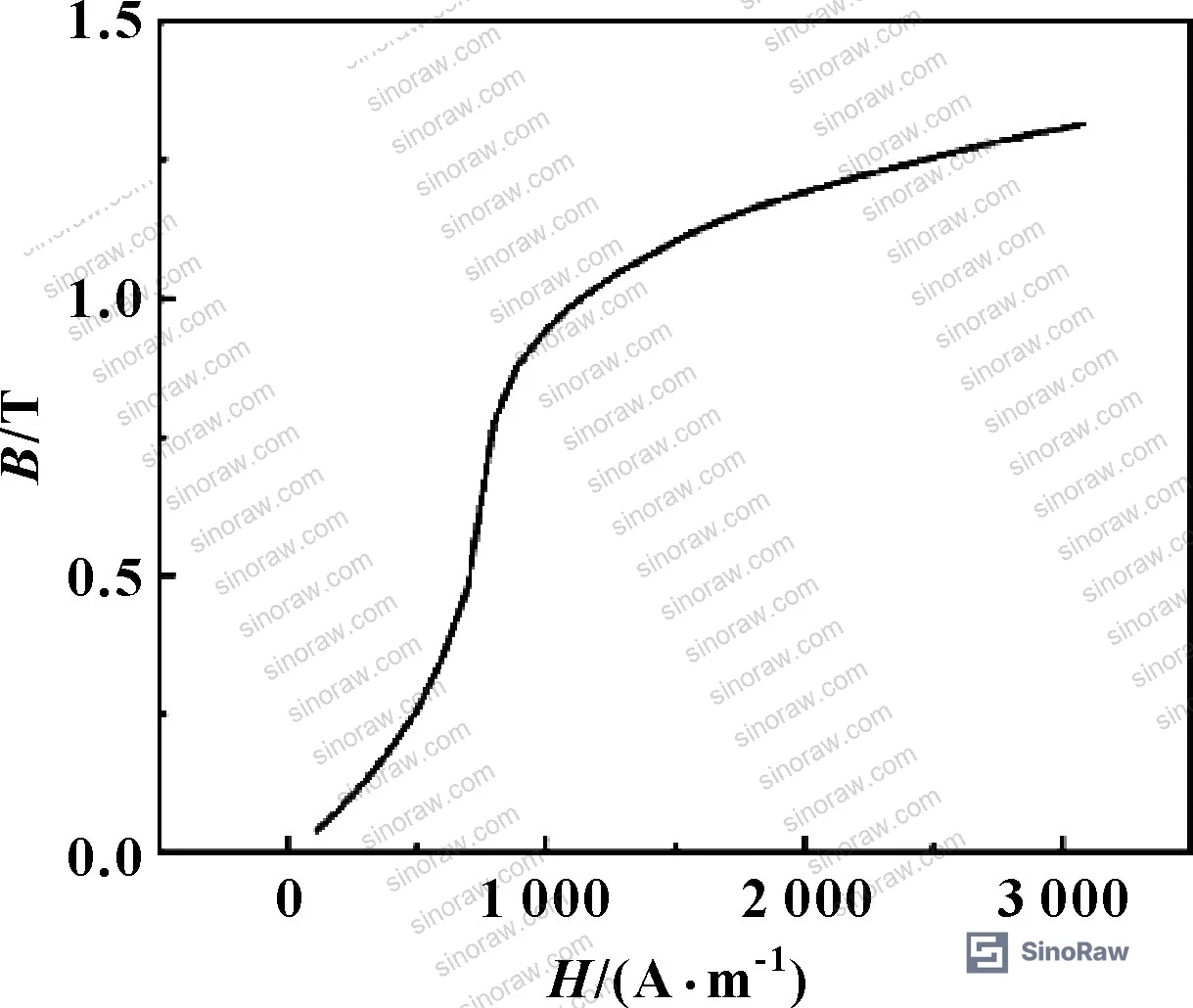
| Saturation magnetization Ms (T) | 0.0203 | 0.0295 | 0.0357 | 0.0464 |
| Density at 25°C (g/cm³) | 1.23 | 1.34 | 1.31 | 1.44 |
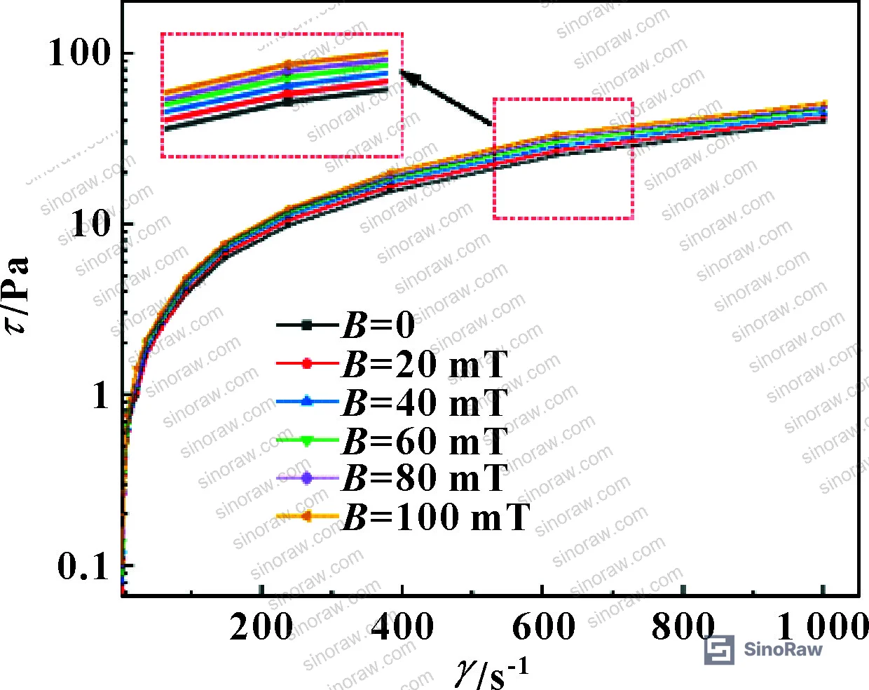
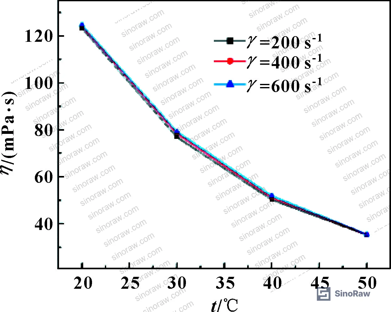
| Dynamic viscosity η (Pa·s) | 80 | 100 | 150 | 180 |
| Evaporation rate at 80°C (g·h⁻¹·cm⁻²) | 1×10⁻⁶ – 9×10⁻⁶ | — | — | — |
Fluid 3# was selected for the test program. Here’s why that matters to procurement: Fluid 4# has higher saturation magnetization (0.0464 T vs. 0.0357 T) but its viscosity of 180 Pa·s generates excessive frictional heating at high shaft speeds, which degrades the magnetization and ultimately destroys the seal. Fluid 3# offers the better balance — adequate Ms at 0.0357 T with viscosity of 150 Pa·s that stays manageable under the thermal load. Fluid 1# and 2# were rejected because their lower Ms values reduce pressure-holding capacity directly.
Honestly, most buyers over-specify saturation magnetization without thinking about the viscosity-speed interaction. A fluid that looks great in a static catalog spec can become the primary failure mechanism once the shaft hits 6,000+ r/min.
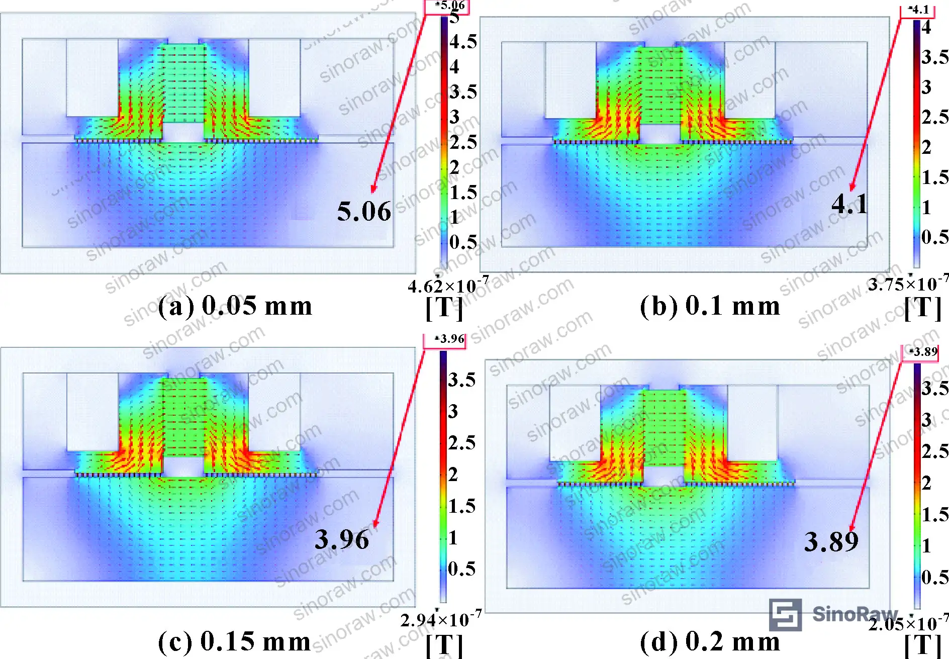
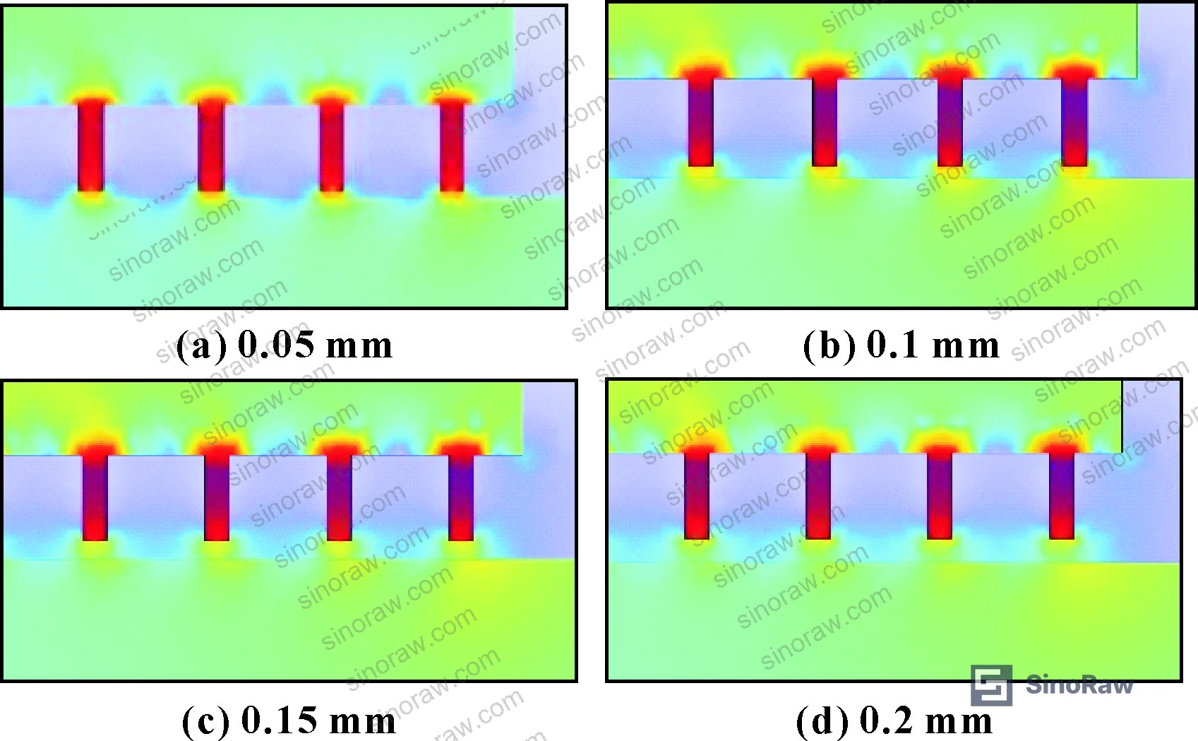
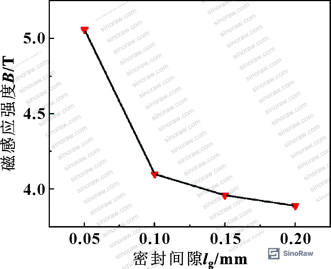
The pressure resistance of the seal is directly proportional to the magnetic field gradient in the sealing gap. This is the governing relationship: as gap size increases, maximum magnetic induction intensity drops — and the drop is non-linear. Simulation results show that when the gap increases from 0.05 mm to 0.1 mm, magnetic induction intensity falls by 18.9%. But from 0.1 mm to 0.15 mm the drop is only 3%, and from 0.15 mm to 0.2 mm it’s just 1%. That step change between 0.05 and 0.1 mm is significant. The 0.1 mm gap was ultimately selected as the design target — it hits the point where magnetic flux is sufficient while remaining manufacturable without excessive assembly risk of tooth contact damage.
The sealing gap must not exceed 0.3 mm in gas turbine applications, and the designed gap for this structure was held at 0.1 mm. The ASTM ISO 9001:2015 Quality management systems framework that qualified suppliers operate under requires documented process controls for gap dimension tolerancing — request evidence of that control in your supplier audit.
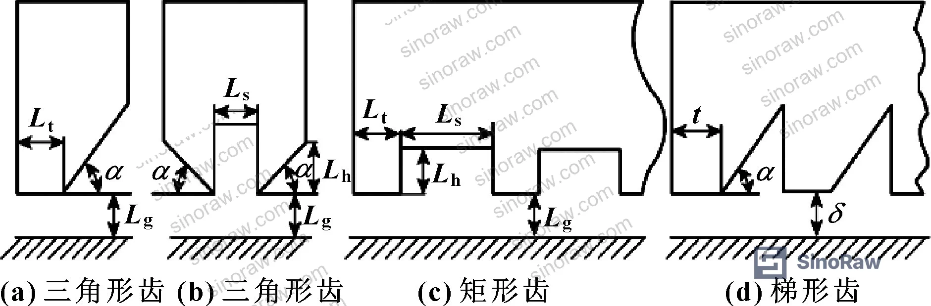
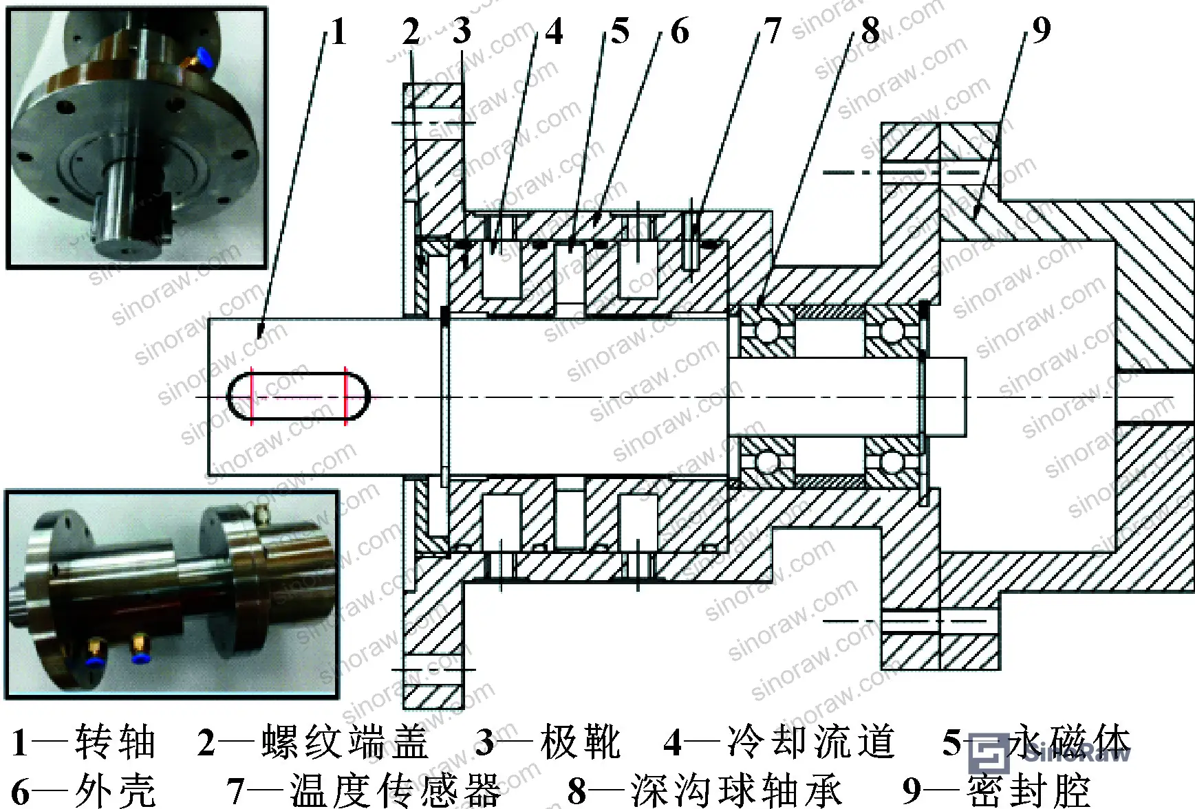
For pole tooth geometry, the evaluation used rectangular teeth on the pole shoe with these dimensions: tooth width Lt = 0.2 mm, slot width Ls = 0.8 mm, tooth height Lh = 0.7 mm, gap Lg = 0.1 mm. The shaft material is 2Cr13 (magnetically permeable), housing is 304 stainless (non-permeable), and the permanent magnets are NdFeB with 16 pieces at ϕ10 mm × 8 mm. Total seal stages: 38. These are not arbitrary numbers — they result from iterative FEA and physical testing. Suppliers who cannot explain their tooth geometry rationale in terms of magnetic field gradient optimization should be disqualified immediately.
Cooling Module Impact and Optimized Pole Tooth Configuration #
This is where the qualification data gets unambiguous.
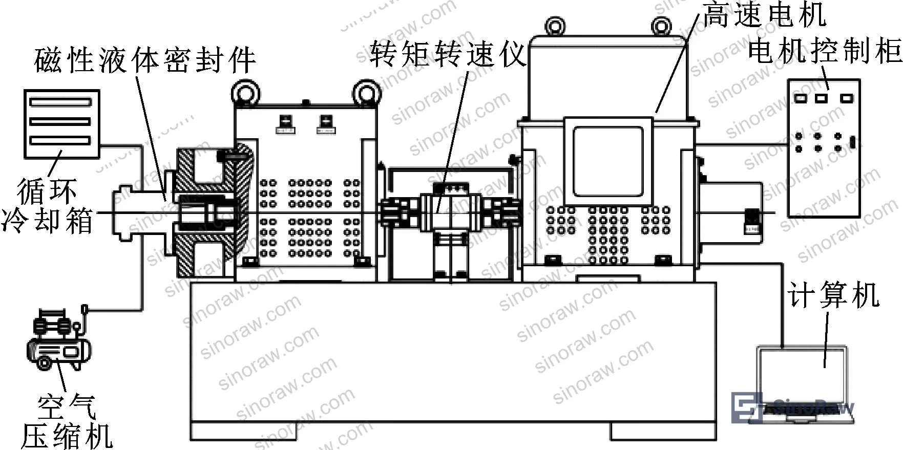
The test bench ran two configurations head-to-head: with and without the integrated cooling module, at incremental shaft speeds up to 8,500 r/min. Results were definitive.
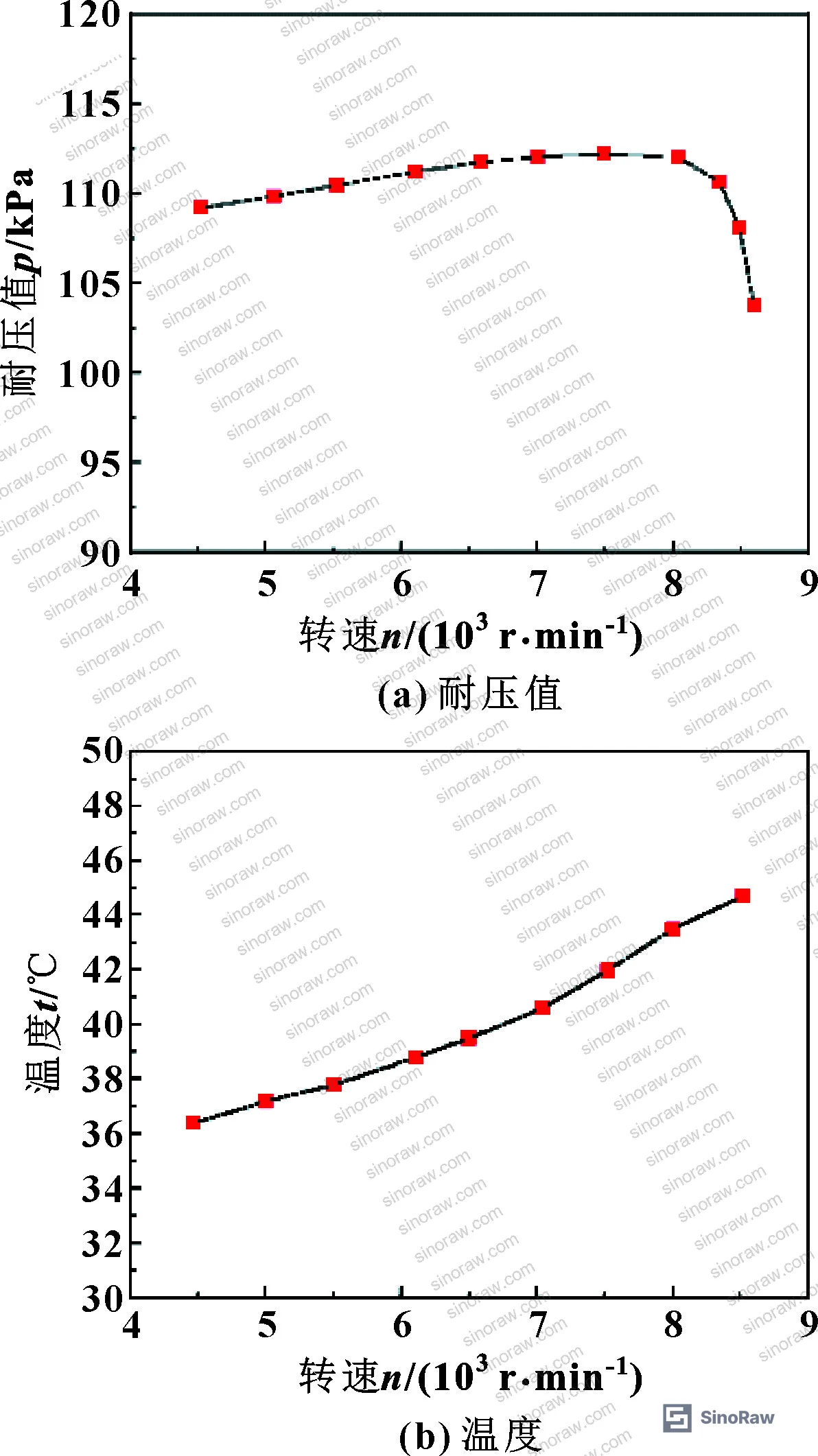
Without cooling module: At 4,471 r/min, pressure resistance was 109 kPa with pole-shoe temperature at 36.3°C. At 8,218 r/min, pressure held at 110 kPa — but above 8,218 r/min the seal failed catastrophically. The magnetic fluid fractured out of the gap.
With cooling module: At 4,471 r/min, pressure resistance reached 160 kPa with pole-shoe temperature at just 5.3°C. At 8,371 r/min, pressure was 167 kPa with temperature at 13.3°C — the 7°C temperature rise from frictional heating actually pressurized the sealed gas slightly. No failure.
The difference: pole-shoe temperature was 31°C lower with cooling, and pressure resistance was 33% higher. In supplier qualification, we found that configurations without active thermal management consistently plateaued at roughly 110 kPa regardless of how well the magnetic fluid was specified — the thermal degradation of magnetization cancelled out any fluid selection advantage.
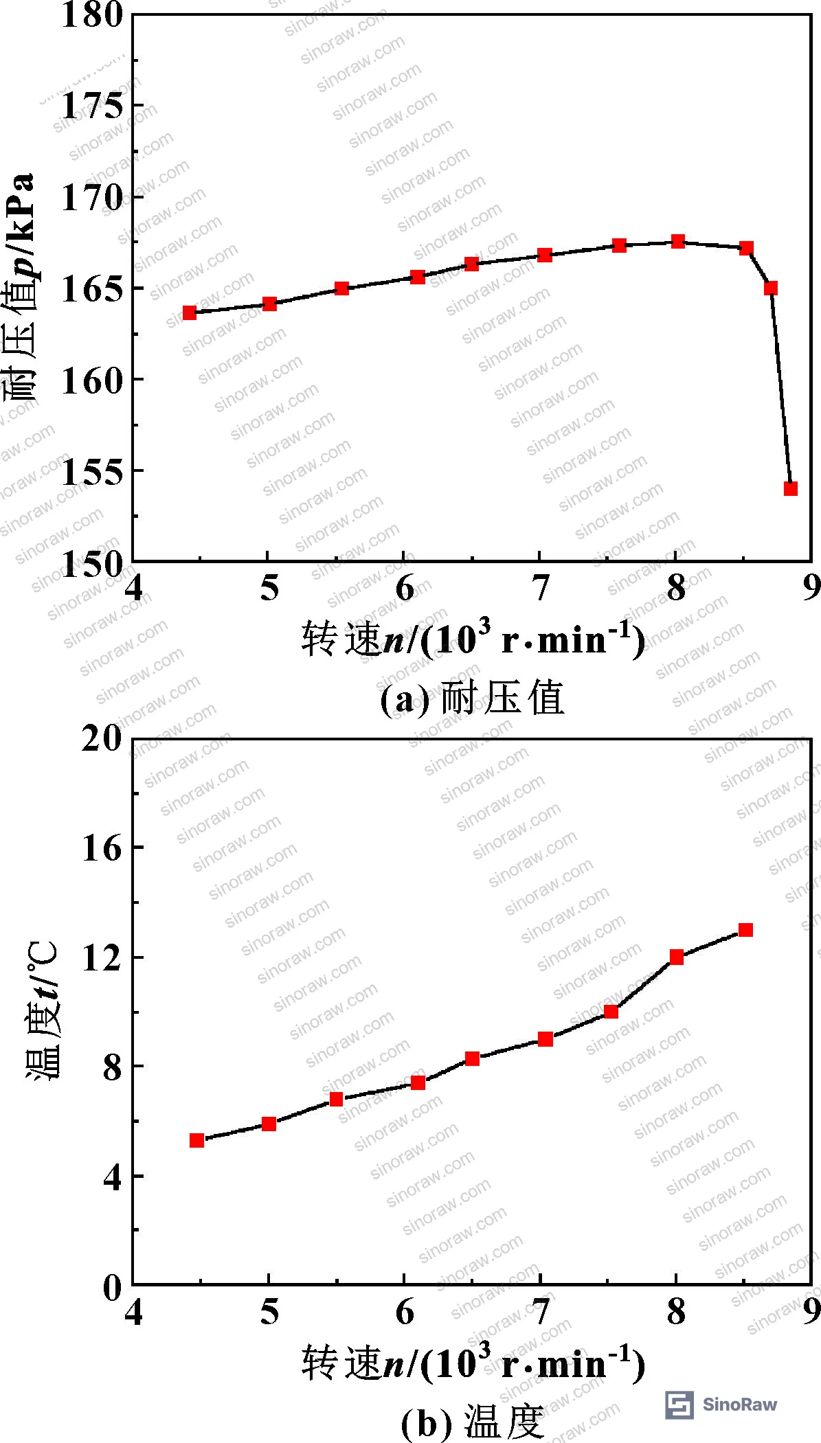
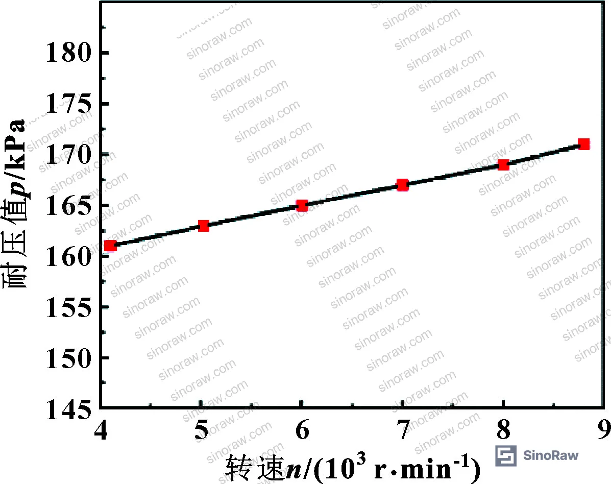
The optimized design takes this further by relocating the pole teeth from the pole shoe to the shaft. When teeth are on the shaft, centrifugal force at high speed actually works in your favor — it throws the magnetic fluid outward onto the pole shoe where it can be recaptured rather than lost from the gap. With teeth on the shaft plus the cooling module, the seal maintained 167 kPa at 8,500 r/min (linear velocity 17.79 m/s) without pressure decay.
For comparison: with teeth on the pole shoe (even with cooling), pressure began dropping at 8,471 r/min. With teeth on the shaft, the seal was still stable at 8,500 r/min at the same 167 kPa. That structural difference — where you machine the teeth — is the margin between meeting spec and exceeding it.
Most procurement teams don’t realize that the tooth location — shaft versus pole shoe — is rarely specified in commercial datasheets, yet it’s the dominant structural variable for performance above 7,000 r/min. Current industry practice is beginning to shift toward shaft-tooth designs for high-speed applications, but many catalog products still default to pole-shoe teeth because they’re easier to manufacture. Verify explicitly.
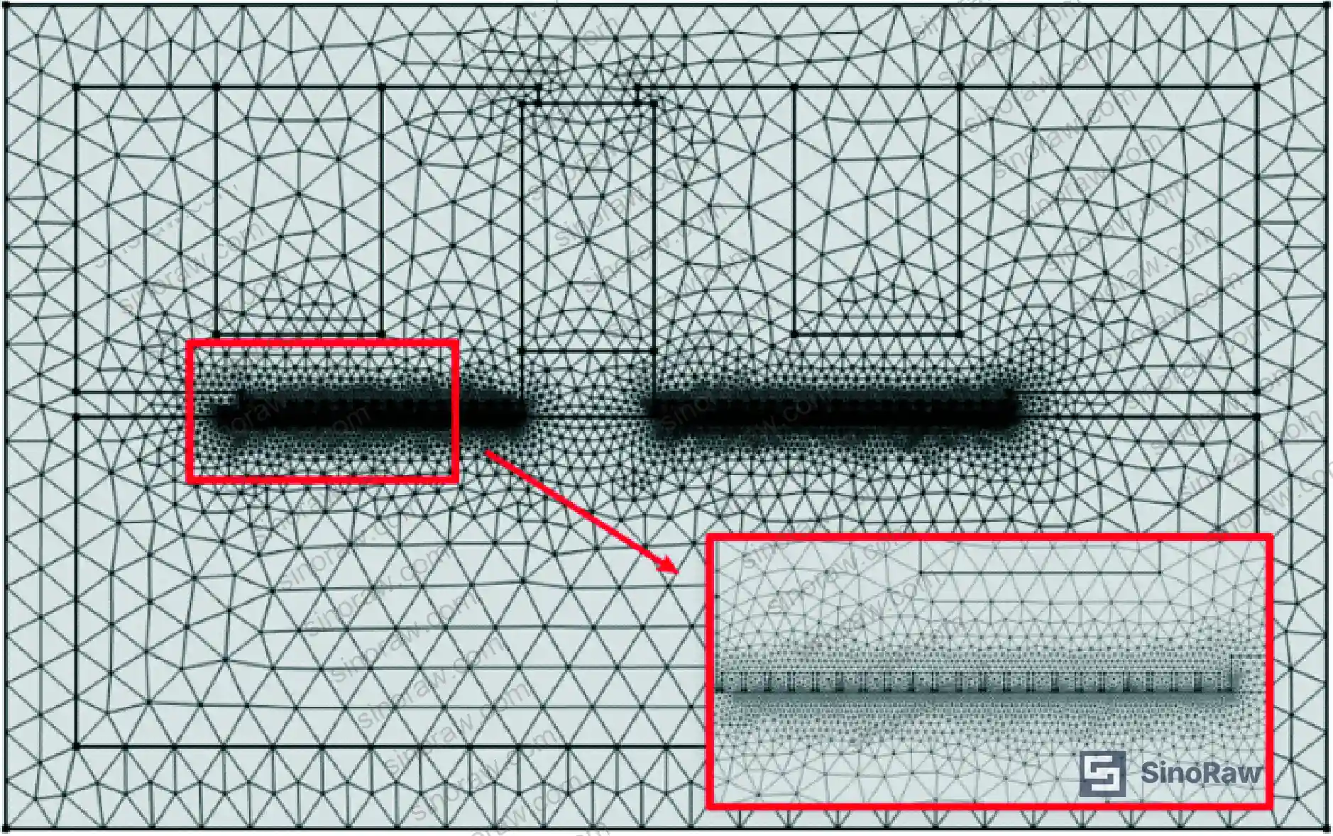
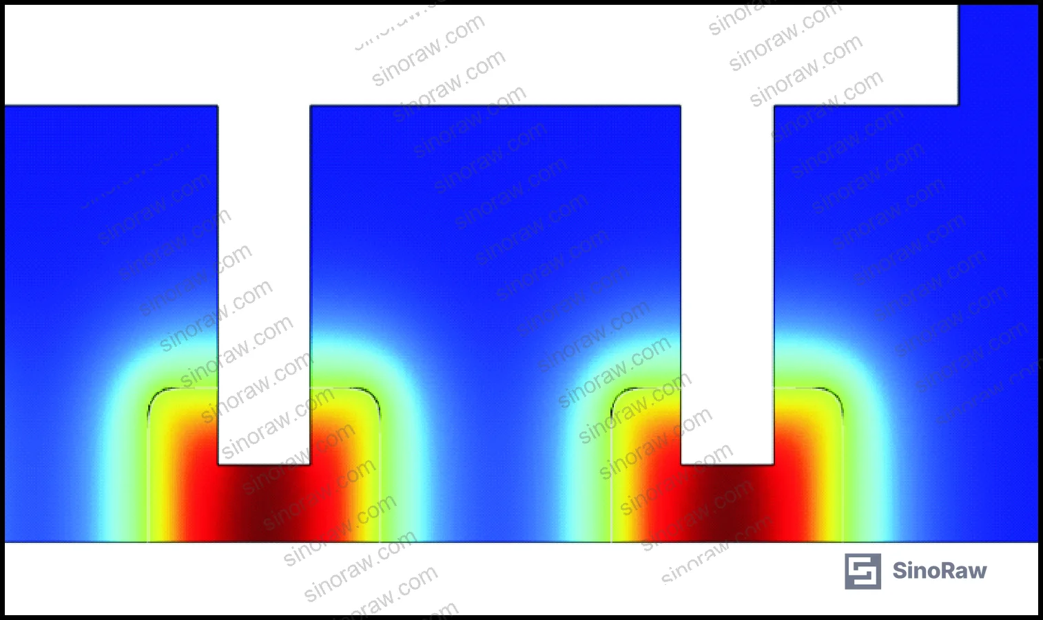
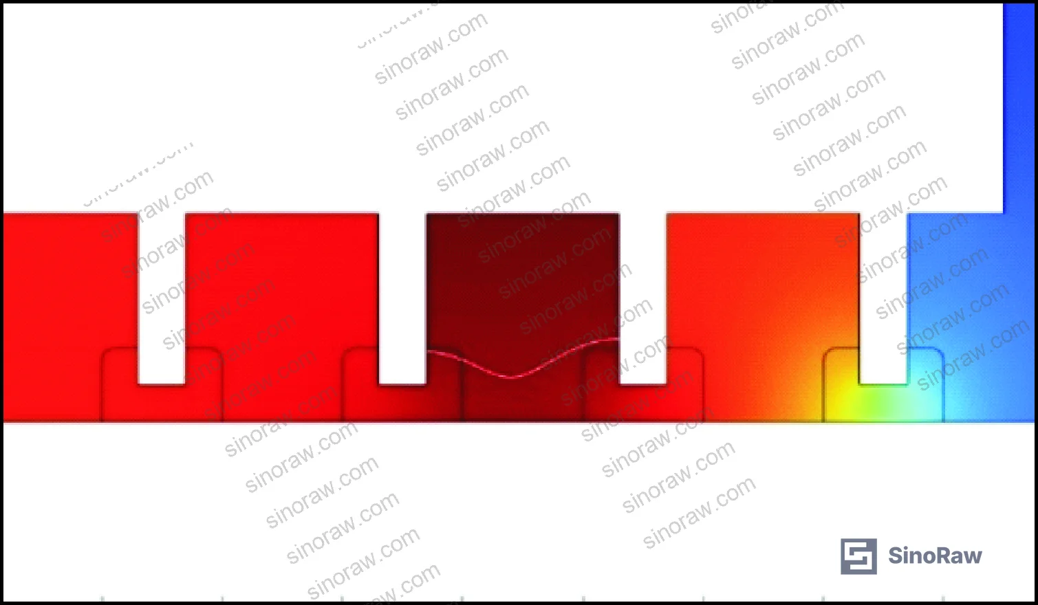
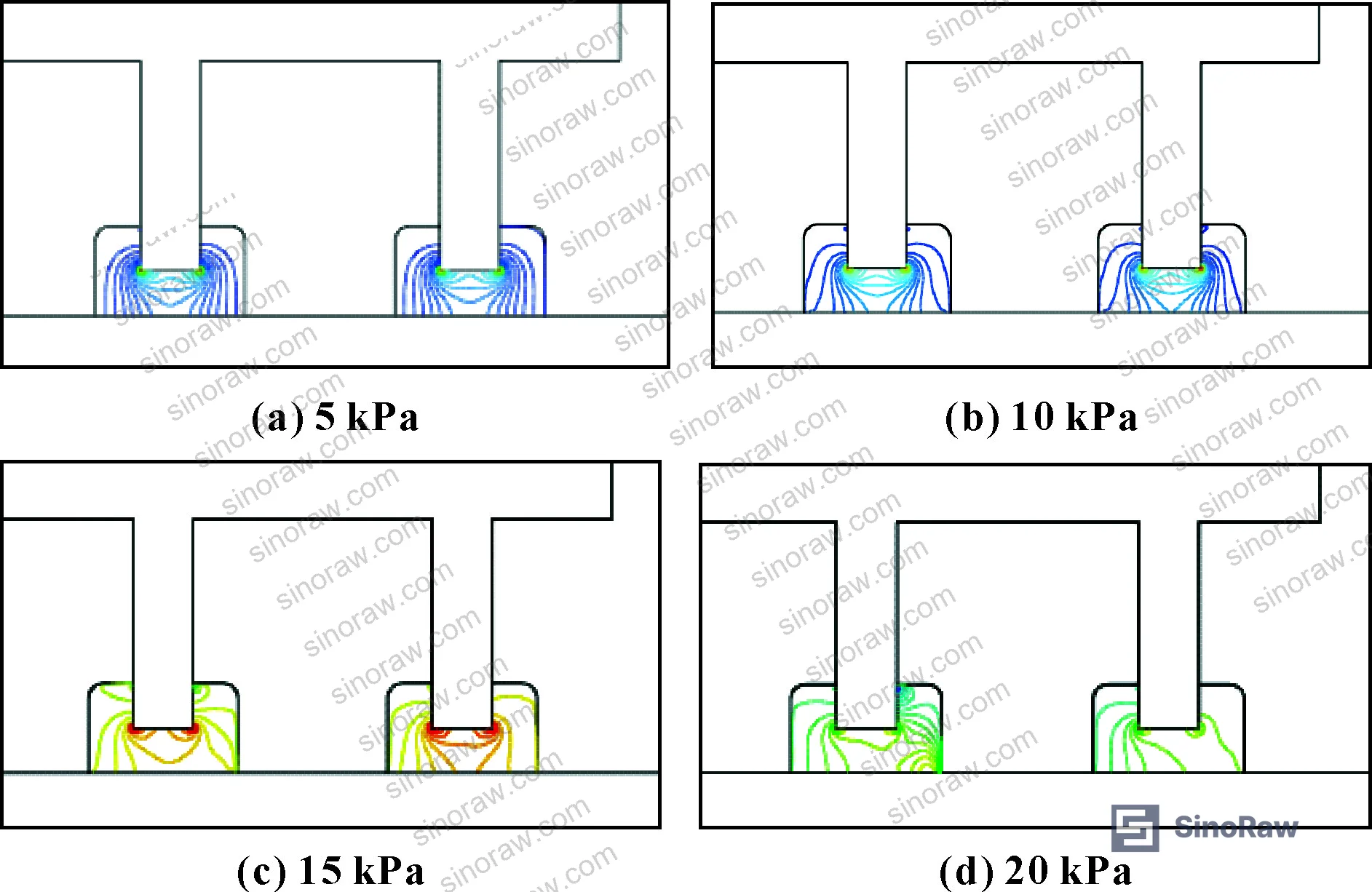
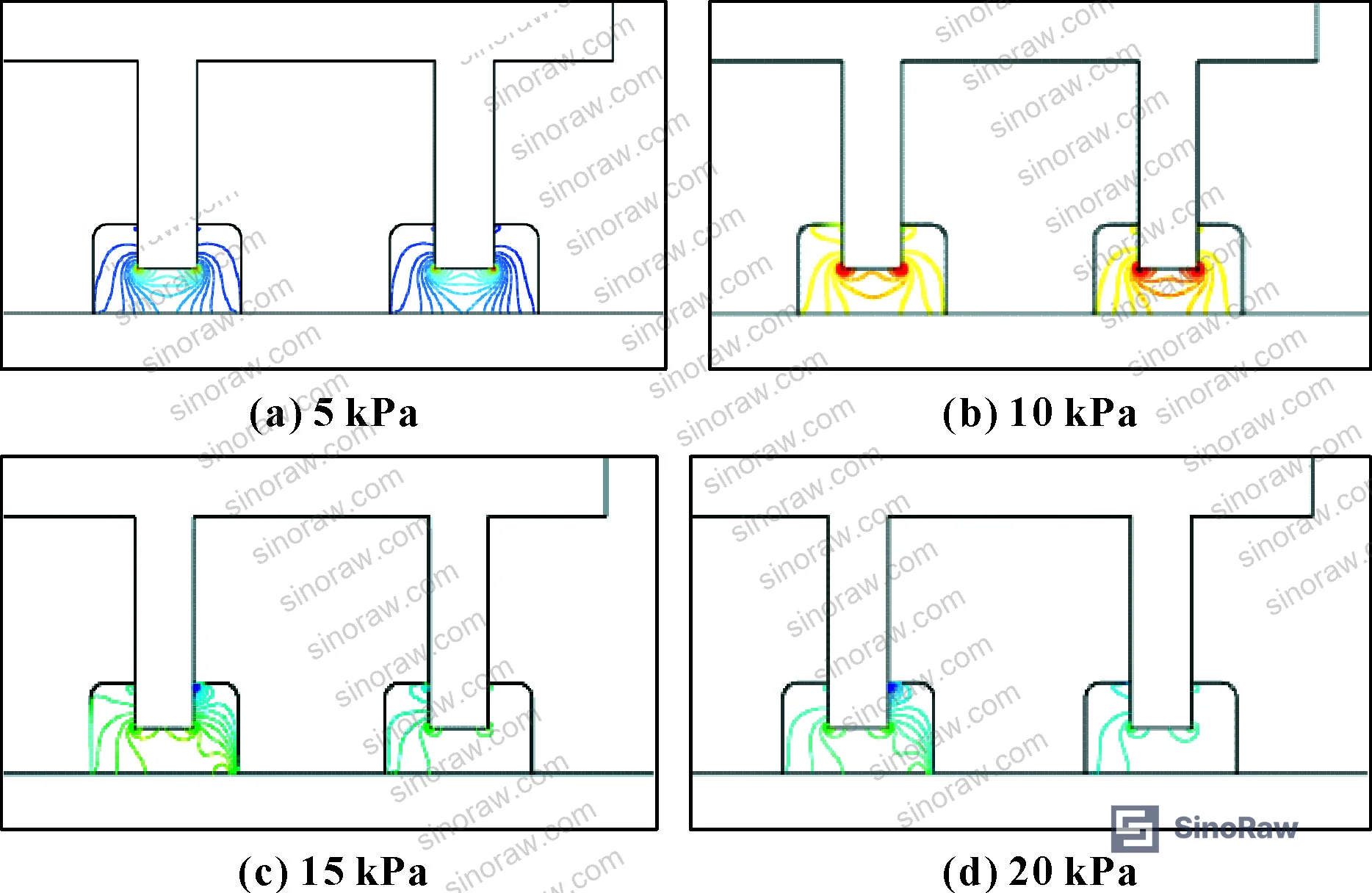
The flow-field simulation at shaft speed 17.79 m/s confirms the mechanism clearly: in the stationary state, fluid is held at the teeth up to the magnetic retention limit. At high speed, shear and centrifugal forces combine to strip fluid from the teeth at lower pressure thresholds. This is not a failure mode — it’s normal physics. But a seal design that doesn’t account for it with either shaft-tooth geometry or active cooling will fail prematurely in service.
Compliance with REACH Regulation (EC) No 1907/2006 is also worth verifying for ester-based magnetic fluids imported from China, particularly regarding iron oxide nanoparticle carrier fluid compositions. And for procurement teams running ISO 14001:2015 Environmental management systems certified operations, request the supplier’s SDS documentation for the magnetic fluid formulation before finalizing the order.
Practical Guidance for Buyers #
When you’re sourcing high-speed magnetic fluid rotary seals from Chinese manufacturers, the performance gap between suppliers is wide — and it’s almost entirely structural, not material.
The single most important document to request is pressure-resistance test data at the target shaft speed with the cooling module installed. Without that data, you have no way to know whether the supplier has validated their design under conditions that match your application. A static pressure test at low speed tells you almost nothing about performance at 8,000+ r/min.
Three variables control seal performance: magnetic fluid viscosity-Ms balance (target Ms ≥ 0.035 T with viscosity ≤ 150 Pa·s for speeds above 5,000 r/min), pole tooth geometry (rectangular preferred for machinability; shaft-tooth configuration preferred for speeds above 7,000 r/min), and sealing gap control (0.1 mm design target, ≤ 0.3 mm absolute maximum). Suppliers who can’t give you specific values for all three in their standard product data are working from an incomplete design.
On pricing: the cooling module integration adds manufacturing complexity and cost. If a supplier quotes an aggressively low price on a high-speed seal, the cooling module is usually what got cut. That’s the wrong tradeoff.
At sinoraw.com, our role as a Guangzhou-based sourcing service is to connect overseas procurement engineers with Chinese manufacturers who can actually document these performance parameters — not just quote low prices. We pre-screen suppliers on test bench capability and data availability before presenting them to buyers.
Need help identifying qualified suppliers for high-speed magnetic fluid rotary seals? Talk to our sourcing team →
Supplier Qualification Questions #
- Can you provide pressure-resistance test data showing sustained performance at 8,500 r/min (linear velocity ≥ 17.79 m/s) with active cooling, specifically demonstrating ≥ 167 kPa holding pressure at the test shaft speed?
- What is the saturation magnetization Ms of the magnetic fluid used in your seals, and at what viscosity value (Pa·s) was it tested — specifically, is Ms ≥ 0.035 T at a viscosity of ≤ 150 Pa·s?
- What is your pole tooth configuration — teeth on the shaft or teeth on the pole shoe — and can you demonstrate with test data that your design maintains pressure stability above 8,000 r/min without the centrifugal-induced pressure drop observed in pole-shoe-tooth designs?
- What is the designed sealing gap in your standard high-speed product, and what is the documented manufacturing tolerance for that gap dimension — specifically, can you confirm the gap is held at 0.1 mm ± what tolerance, with gap never exceeding 0.3 mm?
- In your qualification testing, what was the measured pole-shoe temperature rise at maximum rated shaft speed with and without cooling, and what is the cooling module’s heat removal capacity in Watts?
Sourcing Checklist #
- ☐ Supplier provides pressure-resistance test data showing ≥ 167 kPa at ≥ 8,500 r/min (17.79 m/s linear velocity) with cooling module active
- ☐ Magnetic fluid saturation magnetization Ms ≥ 0.035 T confirmed by characterization data (magnetization curve provided)
- ☐ Magnetic fluid dynamic viscosity ≤ 150 Pa·s at operating temperature, confirmed by rheometer test data
- ☐ Sealing gap dimension confirmed at 0.1 mm design target with documented tolerance control; maximum gap ≤ 0.3 mm
- ☐ Cooling module reduces pole-shoe temperature by ≥ 25°C versus uncooled baseline at the rated shaft speed (≥ 31°C demonstrated in validation testing)
- ☐ Pole tooth geometry documented: rectangular teeth with Lt ≤ 0.5 mm, Ls 2–3 mm, Lh 2–3 mm for 0.1 mm gap (or shaft-tooth configuration explicitly confirmed for speeds > 7,000 r/min)
- ☐ Shaft material confirmed as magnetically permeable grade (e.g., 2Cr13 or equivalent); housing material confirmed as non-permeable (e.g., 304 stainless steel)
- ☐ Media leakage rate documented as < 1×10⁻¹¹ Pa·m³/s (helium mass spectrometer leak detection standard)
Key Specifications Table #
| Parameter | Recommended Value | Verification Method |
|---|---|---|
| Pressure resistance at 8,500 r/min | ≥ 167 kPa | Live bench test with pressure sensor at rated shaft speed, cooling module active |
| Sealing gap (Lg) | 0.1 mm (max 0.3 mm) | CMM dimensional inspection; FEA magnetic field simulation confirming flux adequacy |
| Magnetic fluid saturation magnetization (Ms) | ≥ 0.035 T | VSM (vibrating sample magnetometer) magnetization curve to saturation |
| Magnetic fluid viscosity (η) | ≤ 150 Pa·s at operating temp | Rheometer test at expected operating temperature and shear rate |
| Pole-shoe temperature rise (with cooling) | ≤ 13.3°C above ambient at 8,500 r/min | Thermocouple at pole shoe, logged during speed ramp test |
| Seal stages (N) | ≥ 38 for 167 kPa target | Assembly inspection; correlate with pressure-per-stage design calculation |
| Maximum shaft linear velocity | ≤ 17.79 m/s (8,500 r/min at 40 mm shaft dia) | Tachometer + shaft diameter measurement; pressure stability confirmation |
Can’t find a supplier meeting these specs? Submit your requirements and we’ll match you within 48 hours.
References #
Data source: Structural Optimization and Experimental Validation of High-Speed Magnetic Fluid Rotary Seals for Gas Turbine Applications, R.-W. Hu et al., Tribology International, 2023
Frequently Asked Questions #
What is the primary advantage of magnetic fluid seals over labyrinth seals in high-speed applications?
Magnetic fluid seals achieve media leakage rates below 1×10⁻¹¹ Pa·m³/s — effectively zero leakage by helium mass spectrometer standards — while labyrinth seals have inherent leakage by design. At shaft speeds above 8,000 r/min, magnetic fluid seals with shaft-tooth configuration and active cooling maintained 167 kPa pressure resistance where labyrinth designs would show measurable bypass flow. The magnetic fluid seal is also more compact and requires no contact, eliminating the wear modes that limit labyrinth service life.
Why does pole-shoe temperature matter so much for seal pressure performance?
Seal pressure resistance decreases linearly with temperature because rising temperature reduces the magnetization of the fluid — and magnetization is what holds the fluid in the gap against the pressure differential. The test data showed that removing the cooling module raised pole-shoe temperature by 31°C, which directly caused a 33% drop in pressure resistance. Above 8,218 r/min without cooling, the thermal load caused complete seal fracture.
What is the difference between pole teeth on the shaft versus pole teeth on the pole shoe?
With teeth on the pole shoe, the magnetic fluid in the gap is subject to pure centrifugal ejection at high shaft speed — the fluid gets thrown radially outward and lost from the seal zone. With teeth on the shaft, the centrifugal force instead throws the fluid from the gap onto the pole shoe surface, where it remains in the magnetic circuit and can re-enter the sealing zone. This recycling mechanism is why shaft-tooth design maintained 167 kPa at 8,500 r/min while pole-shoe-tooth design began failing above 8,471 r/min.
What shaft speed range can current magnetic fluid seals handle?
Based on validated test data, a properly designed magnetic fluid seal with rectangular shaft-mounted pole teeth, ester-based fluid at Ms = 0.0357 T and viscosity 150 Pa·s, 38 seal stages, 0.1 mm gap, and an active cooling module sustains 167 kPa at 8,500 r/min (17.79 m/s linear velocity). Beyond 8,500 r/min the current design boundary has not been characterized — buyers with requirements above this speed should request custom design documentation.
How do I verify that a supplier’s magnetic fluid won’t evaporate in service?
Request evaporation rate data at 80°C — the test condition used for ester-based fluids. The measured range for the candidate fluids was 1×10⁻⁶ to 9×10⁻⁶ g·h⁻¹·cm⁻². Ester-based carrier fluids are preferred for high-temperature high-speed applications specifically because their vapor pressure remains low at elevated operating temperatures. Suppliers using hydrocarbon-based carrier fluids without volatility data should be treated with caution for any application above 60°C.
Published by sinoraw.com Technical Team | Request a sourcing quote


