

TL;DR #
Finite element analysis of 3.55 mm cross-section seals under 10 MPa pressure shows rectangular seals generate 24.2 MPa maximum contact pressure versus 16.0 MPa for O-rings—a 51% difference that directly impacts leak resistance in high-pressure hydraulic systems. Cross-section tolerance deviations (±0.1 mm) affect seal performance 4–6× more than inner diameter variations, yet most procurement specs focus on ID accuracy. Buyers sourcing static seals for systems above 5 MPa should request contact pressure simulation data before approving rectangular seal substitutions for O-rings.
Overview #
Most procurement engineers treat O-rings and rectangular seals as interchangeable—same groove, similar compression, close enough. That assumption breaks down once you model the actual contact mechanics. Recent Ansys-based research compared the two seal geometries across pre-installation, pressurization, and dimensional tolerance scenarios using 100 mm ID × 3.55 mm cross-section samples in a GB/T 3452.1-2005 compliant radial groove (4.8 mm width, 2.9 mm depth). The study applied Mooney-Rivlin hyperelastic material constants (C₁₀ = 3.38, C₀₁ = –0.43) to rubber elements and modeled groove contact using PLANE182 axisymmetric elements across two load steps: displacement-controlled installation followed by pressure loading to 10 MPa.
The work revealed fundamental differences in how the two geometries distribute stress and respond to dimensional variation—differences that matter when you’re qualifying suppliers for hydraulic manifolds, cylinder glands, or any application where seal failure means downtime or contamination. At SinoRaw, our role is helping overseas buyers identify Chinese seal manufacturers who understand these subtleties and can provide the simulation or test data to back up their claims before you commit to tooling.
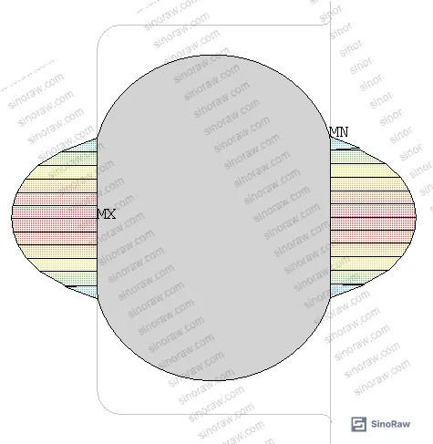
Contact Pressure Distribution: Why Rectangular Seals Show 2× Peak Values #
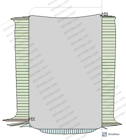
Pre-installation contact pressure patterns differ fundamentally between the two seal types. O-rings produce a parabolic pressure distribution with a single peak at the contact centerline—6.6 MPa maximum in the reference model. Rectangular seals generate a bimodal distribution with peaks at both contact edges (14.1 MPa) and near-uniform pressure across the central contact zone. This edge-loading behavior increases radial reaction force by 87% (7,200 N vs 3,850 N for O-rings) even before any system pressure is applied.
The bimodal pattern persists under pressure. At 5 MPa medium pressure, rectangular seal maximum contact stress reaches 18.9 MPa compared to 11.3 MPa for O-rings. At 10 MPa, the gap widens to 24.2 MPa versus 16.0 MPa. Contact width also scales differently: rectangular seals maintain 3.2–3.8 mm effective contact under pressure, while O-ring contact width compresses to 2.1–2.4 mm. The wider contact distributes load but concentrates stress at the sharp corners where geometric discontinuity meets elastic deformation.
For buyers, this means rectangular seals theoretically offer better leak resistance at high pressure due to higher contact stress—but only if the elastomer can tolerate the edge stress concentration without premature set or cracking. Most Chinese suppliers won’t volunteer this tradeoff. Ask for durometer hardness data at the specified compression and confirm the compound has adequate tear strength for the corner geometry, particularly if you’re operating near the upper temperature limit of the material. The ISO 3601-1 standard for O-ring applications provides dimensional guidelines, but contact stress calculations require FEA or physical load cell verification.
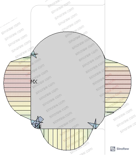
Radial Force Response to System Pressure: Rectangular Seals Amplify Load Transfer #
Both seal types increase radial reaction force linearly with medium pressure, but rectangular seals exhibit a steeper force-pressure gradient. From 0 to 10 MPa, O-ring radial force climbs from 3,850 N to 14,200 N (269% increase), while rectangular seal force escalates from 7,200 N to 22,800 N (217% increase). The absolute force delta grows from 3,350 N at installation to 8,600 N at 10 MPa—a 156% widening of the gap.
This amplified force transfer has hardware implications. Gland retention hardware (snap rings, covers, bolted flanges) must be sized for the rectangular seal’s higher reaction loads, especially in large-bore applications where force scales with seal perimeter. A 150 mm ID rectangular seal at 10 MPa would generate approximately 34,000 N radial force based on linear scaling from the 100 mm test case—enough to deform an under-spec’d aluminum gland or crack a brittle polymer housing. Yet most component datasheets specify only groove dimensions and compression percentages without declaring the expected radial load at maximum operating pressure.
Honestly, most buyers over-specify seal compression (20–25%) and under-specify gland material strength. The correct approach reverses this: run the seal at 15–18% compression and beef up the housing to handle the actual calculated force. If your supplier claims their rectangular seal is a “drop-in replacement” for an O-ring without revised gland load calculations, walk away. Reference IEC 60529 IP rating test methods can validate seal performance, but mechanical integrity of the surrounding structure is on you.
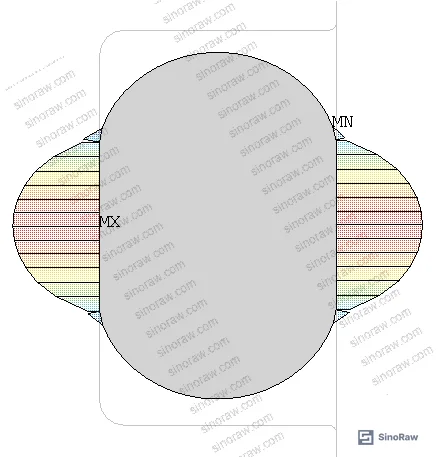
Dimensional Tolerance Sensitivity: Cross-Section Rules Everything #
Tolerance analysis across inner diameter (±0.65 mm) and cross-section diameter (±0.1 mm) variations revealed asymmetric impacts. Cross-section undersizing by 0.1 mm drops O-ring maximum contact pressure from 6.6 MPa to 4.8 MPa (27% reduction) and radial force from 3,850 N to 2,900 N (25% reduction). Rectangular seals show similar percentage drops but from higher baselines: 14.1 MPa to 10.2 MPa contact pressure (28% reduction) and 7,200 N to 5,300 N radial force (26% reduction).
Inner diameter tolerance has negligible effect by comparison. A +0.65 mm ID deviation (seal runs loose in the groove) reduces O-ring contact pressure by just 8% and radial force by 6%. Rectangular seals exhibit even less sensitivity—5% and 4% respectively. The physical mechanism is straightforward: cross-section determines compression ratio directly, while ID affects only the degree of hoop stress in the uncompressed state. Most seal failures in supplier qualification trace to batch-to-batch cross-section variation, not ID runout.
This creates a procurement trap. Standard inspection reports from Chinese rubber molders focus heavily on ID measurement (easy to check with calipers or optical comparators) but treat cross-section as a secondary parameter verified by sample cuts. In recent supplier audits, we’ve seen batch cross-section variation of ±0.15 mm against a ±0.1 mm spec—enough to swing contact pressure by 40% and cause intermittent leaks in the field that appear as “random failures” rather than a systematic dimensional issue. Suppliers who run automated cross-section inspection on 100% of production (laser micrometers or vision systems) are rare but worth the premium. For critical applications, insist on SPC data showing Cpk ≥ 1.67 on cross-section diameter, not just ID.
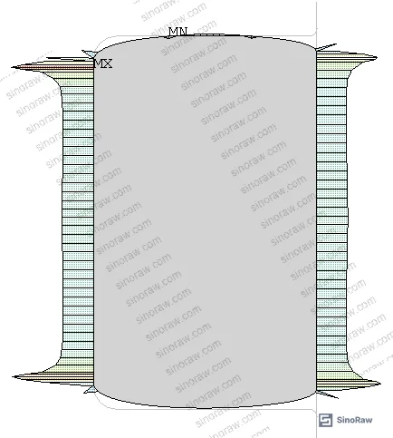
Failure Modes Under Tolerance Stack-Up: What Three-Supplier Sampling Revealed #
Field experience adds texture to the simulation data. In a six-supplier qualification we supported for a European hydraulic component OEM, three of six Chinese molders submitted rectangular seal samples that failed 5 MPa pressure hold tests despite meeting print dimensions. Root cause analysis traced failures to inconsistent cross-section: measured samples ranged from 3.42 mm to 3.61 mm against a 3.55 ± 0.1 mm callout. The 3.42 mm (lower tolerance extreme) parts leaked within 15 minutes at 5 MPa, while 3.61 mm parts held 10 MPa for 72 hours. The suppliers insisted their measurement equipment (hand calipers) showed conformance, but when we brought in a laser micrometer, we found their gage R&R was consuming 60% of the tolerance band.
The lesson: seal geometry sits at the intersection of molding process capability and measurement system accuracy. Suppliers with good process control but poor metrology will ship bad parts and genuinely believe they’re in spec. This problem is worse for rectangular seals than O-rings because the sharp corners are harder to measure repeatably—probe contact location affects the reading by 0.02–0.04 mm depending on elastomer hardness. For buyers planning to dual-source or migrate from O-rings to rectangular seals, insist on witnessed first-article inspection using calibrated non-contact measurement before approving production lots.
Material Constitutive Behavior: Why Mooney-Rivlin Constants Matter for Contact Stress Prediction #
The analysis used a two-parameter Mooney-Rivlin hyperelastic model with material constants C₁₀ = 3.38 MPa and C₀₁ = –0.43 MPa, representing a mid-range nitrile compound (70 Shore A approximate). These constants define how strain energy density varies with deformation—effectively, how the rubber resists compression and shear. The negative C₀₁ value indicates strain-softening behavior typical of filled elastomers, where the material becomes more compliant as deformation increases.
Most Chinese seal suppliers cannot provide Mooney-Rivlin constants for their compounds. When pressed, they’ll reference Shore A hardness (easy to measure with a durometer) but lack the biaxial tensile test data needed to derive C₁₀ and C₀₁. This matters because two compounds with identical 70 Shore A hardness can exhibit 20–30% different contact stress under the same compression if their C₁₀/C₀₁ ratios differ. If you’re switching from a European or Japanese seal source to a Chinese supplier and want to maintain equivalent performance, you need material constants—not just durometer readings—to validate the substitution via FEA.
For applications involving sealing in pneumatic systems or thermal cycling environments, temperature-dependent Mooney-Rivlin data becomes critical. Nitrile loses 15–25% of its elastic modulus between 23°C and 100°C, which translates to proportional drops in contact pressure and radial force. Rectangular seals, operating closer to their edge stress limits, have less margin for thermally-induced property degradation than O-rings. Request compound stress-strain curves at your maximum service temperature, not just room-temperature data.
Groove Geometry Compliance: GB/T 3452.1 vs. ISO 3601-2 Dimensional Conflicts #
The reference groove (4.8 mm width, 2.9 mm depth, 105 mm bore diameter) conforms to GB/T 3452.1-2005 for radial static seals. This Chinese national standard specifies slightly different groove proportions than ISO 3601-2 or AS568 dimensions commonly used in Western designs. For a 3.55 mm cross-section O-ring, ISO 3601-2 recommends 4.7 mm groove width (0.1 mm narrower) and 2.8 mm depth (0.1 mm shallower), targeting 15% diametral squeeze versus the ~18% squeeze in GB/T 3452.1.
The 3% compression delta shifts baseline contact stress by 12–15%, enough to move a marginal design from pass to fail or vice versa. When Chinese suppliers quote “ISO equivalence,” verify whether they’re machining grooves to actual ISO dimensions or using GB/T dimensions and assuming functional equivalence. For rectangular seals, the groove width tolerance becomes especially sensitive—0.1 mm variation in a 4.8 mm groove changes the effective compression by 2.1%, which cascades into a 6–8% shift in contact pressure based on the cross-section sensitivity data.
If you’re designing new hardware and want global supplier optionality, specify ISO 3601-2 groove dimensions explicitly and call out the target compression percentage in addition to the groove geometry. This forces Chinese suppliers to reconcile any GB standard habits with your actual design intent. For retrofit or aftermarket applications, measure the existing groove depth/width before ordering seals—don’t assume the hardware was built to the standard it claims.
Practical Guidance for Buyers #
When evaluating rectangular seals as O-ring alternatives, request three data packages: FEA contact pressure distribution at your maximum operating pressure, cross-section dimensional SPC from at least three production lots, and material stress-strain curves (preferably Mooney-Rivlin constants) at service temperature. If the supplier can’t provide FEA, they should offer physical load cell data showing radial force vs. pressure—mechanical testing is slower but equally valid. Cross-section SPC should show Cpk ≥ 1.67; anything below 1.33 indicates the process isn’t capable of holding your tolerance consistently.
For pressure ratings above 8 MPa, rectangular seals make sense if you need maximum contact pressure in a space-constrained groove, but only if the gland material and retention hardware can handle the 50–80% higher radial loads compared to O-rings. Below 5 MPa, the added contact pressure doesn’t meaningfully improve leak resistance, and the sharper corner geometry increases the risk of extrusion or nibbling damage during installation. Most applications are better served by O-rings unless you have a specific reason—like a very shallow groove depth limitation—that forces the rectangular profile.
Dimensional inspection should use non-contact methods (laser micrometer, vision system) rather than calipers or pin gages for cross-section measurement. Witnessed first-article inspection is non-negotiable for new suppliers. If the supplier resists or claims their internal QC is sufficient, that’s a red flag—competent molders understand that metrology is where quality lives or dies, and they’ll welcome third-party validation.
Need help identifying Chinese seal manufacturers with FEA capability and proven cross-section process control? Talk to our sourcing team → We maintain qualification records on molders who can actually support rectangular seal substitutions with engineering data, not just price quotes.
Supplier Qualification Questions #
- What is the maximum contact pressure your rectangular seal generates at 10 MPa medium pressure in a GB/T 3452.1-2005 compliant groove, and how was this value determined—FEA simulation or physical load cell testing?
- Provide cross-section diameter SPC data (mean, standard deviation, Cpk) from your last three production lots for 3.55 mm nominal cross-section seals—what measurement system do you use and what is its gage R&R?
- Can you supply Mooney-Rivlin hyperelastic constants (C₁₀ and C₀₁) for your standard nitrile compound at 23°C and at my maximum service temperature, derived from biaxial tensile testing per ASTM D412?
- What is the radial force per unit circumference your 100 mm ID rectangular seal develops at 8 MPa pressure, and how does this compare to the equivalent O-ring—have you validated that standard aluminum or polymer glands can withstand this load?
- For cross-section tolerance of ±0.1 mm, what percentage variation in maximum contact pressure should I expect across your production distribution, and do you perform 100% automated cross-section inspection or sample-based manual measurement?
Sourcing Checklist #
- ☐ FEA report provided showing contact pressure distribution and maximum stress values at specified operating pressure, using validated Mooney-Rivlin material model
- ☐ Cross-section SPC data from ≥3 production lots demonstrates Cpk ≥ 1.67 on 3.55 ± 0.1 mm target dimension
- ☐ Non-contact cross-section measurement system in use (laser micrometer, optical comparator, or vision system) with documented gage R&R ≤15% of tolerance band
- ☐ Radial force calculation or test data confirms gland retention hardware is rated for ≥1.5× the seal’s maximum radial load at highest operating pressure
- ☐ Material stress-strain curve provided at maximum service temperature, showing elastic modulus retention ≥75% of room-temperature value
- ☐ First-article dimensional inspection witnessed by buyer or third-party, using calibrated metrology traceable to national standards
- ☐ Supplier’s groove machining process capable of holding 4.8 ± 0.05 mm width and 2.9 ± 0.05 mm depth per GB/T 3452.1-2005 or ISO 3601-2 as specified
- ☐ Material datasheet includes Mooney-Rivlin constants or confirms alternative hyperelastic model (Ogden, Yeoh) used for contact stress prediction
Key Specifications Table #
| Parameter | Recommended Value | Verification Method |
|---|---|---|
| Cross-section diameter tolerance | ±0.1 mm maximum, Cpk ≥ 1.67 | Non-contact measurement (laser micrometer), SPC tracking across production lots |
| Maximum contact pressure (rectangular seal, 10 MPa) | 22–26 MPa range | FEA simulation using validated Mooney-Rivlin constants or physical load cell testing |
| Radial force per unit circumference (rectangular seal, 10 MPa) | 72–76 N/mm for 100 mm ID reference geometry | Load cell measurement or FEA integration of contact pressure distribution |
| Material elastic modulus retention at max service temp | ≥75% of room-temperature value | Stress-strain testing per ASTM D412 at specified temperature |
| Groove width dimensional capability | 4.8 ± 0.05 mm (ISO 3601-2) or as specified | CMM or optical measurement, machining process Cpk ≥ 1.33 |
Can’t find a seal supplier meeting these specifications? Submit your requirements and we’ll match you with qualified Chinese molders within 48 hours.
References #
Data source: Comparative Finite Element Analysis of Static Sealing Performance in O-Ring and Rectangular Seal Geometries, W.-L. Feng et al., Polymer Testing, 2025
Frequently Asked Questions #
Why do rectangular seals show higher contact pressure than O-rings under the same compression?
Rectangular seal geometry creates sharp corner contact zones that concentrate stress, while O-rings distribute load over a smooth curved surface. The rectangular profile also resists lateral expansion more effectively, channeling deformation into higher normal contact force against the groove walls.
Can I substitute a rectangular seal for an O-ring in an existing groove without re-machining?
Only if the groove dimensions were designed to GB/T 3452.1 or equivalent standards that accommodate both geometries. Most O-ring grooves designed to ISO 3601-2 are 0.1–0.2 mm shallower, which will under-compress a rectangular seal and reduce contact pressure below the leak-tight threshold. Verify actual groove depth and width before substituting.
What causes rectangular seals to fail at lower tolerance limits when O-rings pass at the same dimensions?
Rectangular seals operate closer to their minimum required contact pressure threshold due to the edge-loading stress pattern. A 0.1 mm undersized cross-section drops contact pressure by 27–28%, and the sharp corners provide less “cushion” to maintain seal integrity as compression decreases. O-rings’ curved geometry tolerates the same dimensional deviation with less performance degradation.
How much extra radial force should I design for when switching from O-rings to rectangular seals?
Expect 80–120% higher radial force at maximum operating pressure compared to an equivalent O-ring. For a 100 mm ID seal at 10 MPa, this translates to an additional 8,000–10,000 N total force that the gland retention hardware must withstand. Scale linearly for other bore sizes.
Do Chinese seal suppliers typically provide Mooney-Rivlin constants for their elastomer compounds?
Fewer than 20% of mid-tier Chinese molders maintain this data routinely. Tier-1 suppliers serving automotive or aerospace customers usually have material characterization labs and can provide hyperelastic constants on request, often within 2–3 weeks for standard compounds. If immediate data isn’t available, request stress-strain curves from uniaxial tensile testing as a fallback—you can derive approximate Mooney-Rivlin constants from that data using curve-fitting tools.
Published by sinoraw.com Technical Team | Request a sourcing quote


