

TL;DR #
In controlled temperature-rise testing, an improperly terminated aluminum wire connection reached 308.8 °C and caused terminal melt-failure, while a correctly torqued copper wire connection at identical load conditions peaked at 110 °C — a 2.8× difference that determines whether a wired enclosure becomes a fire hazard. For buyers sourcing barrier films, thermal laminates, or insulating sleeves used in electrical assemblies, this data directly informs the thermal threshold your materials must survive under abnormal-use conditions. Specify terminal enclosure materials with documented ball-pressure test ratings at 125 °C ±2 °C minimum, and require supplier furnish actual temperature-rise test data — not just a GB/T 2099 compliance declaration.
Overview #
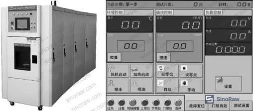
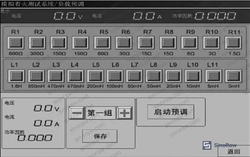
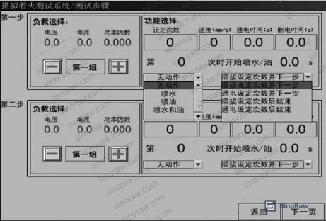
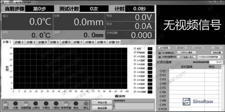
Procurement engineers evaluating thermal barrier and insulating film materials for electrical enclosures often focus on tensile strength and dielectric values while underestimating the real-world thermal loading those materials will face at connection points. The data reviewed here comes from a systematic laboratory investigation by a manufacturer-side testing center, using a purpose-built multi-environment test platform capable of 25–100 °C ambient simulation, 0–300 V adjustable voltage, 0–100 A load control, and integrated spray-water and oil-mist simulation. Three distinct wiring scenarios were tested across standardized conditions (250 V, rated current, power factor 0.75–0.8), with thermal imaging used to capture peak temperatures at terminal contact zones.
The findings are unambiguous and have direct implications for anyone specifying the insulating or barrier materials that surround wiring terminal assemblies. An aluminum wire connection under 20 A load at 45 °C ambient reached 308.8 °C. The same terminal with correctly specified copper wire peaked at 110 °C. The terminal enclosure material — in this case PC (polycarbonate) — survived in the copper case and melted in the aluminum case. This is not an edge case. It is a routine failure mode that barrier and thermal film buyers should build into their qualification criteria.
For sourcing teams working with barrier films used in electrical insulation applications, the takeaway is simple: your film’s rated service temperature must clear the worst-case terminal temperature by a meaningful margin, not just the nominal operating temperature.
Wiring Material and Terminal Connection: How They Drive Thermal Barrier Film Failure #
The three experiments conducted on the test platform produced temperature data that should be directly translated into material specification requirements.
Experiment 1 — Copper vs. Aluminum Wire (20 A, 250 V, 45 °C ambient, 1.0 mm² conductor, post-water-spray)
| Condition | Peak Terminal Temperature | Terminal Outcome |
|---|---|---|
| Aluminum wire, 1.0 mm², torqued | 308.8 °C | Terminal melted, socket destroyed |
| Copper wire, 1.0 mm², torqued | 110 °C | Terminal intact, socket functional |
| Copper wire, 1.5 mm², torqued (Experiment 2, 10 A) | 42.5 °C | Normal, no degradation |
The 308.8 °C figure is the critical datum. Any insulating or barrier film used as a sleeve, wrap, or enclosure liner in a terminal zone must sustain continuous exposure above that threshold if it is intended to survive an aluminum-wire abuse scenario. Most standard PET films are rated to 150–180 °C continuous — that is not sufficient coverage for this failure mode.
Experiment 2 — Torqued vs. Untorqued Termination (10 A, 250 V, 25 °C ambient, 1.5 mm² copper)
An untorqued terminal — meaning a screw not driven to the specified 0.53 N·m torque — produced a peak temperature of 1,100.8 °C at the wire contact point. The torqued terminal at identical load conditions reached 42.5 °C. This is not a typo. The contact resistance generated by a loose mechanical connection under P = I²R physics produces catastrophic thermal output at currents that appear entirely normal on the circuit.
The implication for barrier film selection is that materials specified for “normal operating” temperature ranges simply will not function as a thermal barrier during this failure mode. Films intended for any use near wiring terminals need to be evaluated against abuse-condition temperatures, not just steady-state ratings.
Experiment 3 — Mechanical Shock (1,000-cycle drum test) + Temperature Rise (16 A, 250 V, 25 °C ambient, 1.0 mm² copper)
After 1,000 drum-rotation cycles simulating drop and impact abuse, inferior-quality terminals showed visible screw loosening. Subsequent temperature-rise testing showed a peak of 330 °C at those terminals, with melt-failure. High-quality terminals under identical mechanical abuse showed no significant loosening, and post-shock temperature rise peaked at only 75 °C.
The gap between 330 °C and 75 °C — from identical mechanical inputs — is entirely a function of terminal build quality. For barrier film buyers specifying enclosure liners or wrap films, this means your material performance envelope needs to account for the terminal quality of the assembly it protects, which you may not control.
Thermal Barrier Film Requirements Derived from Terminal Temperature-Rise Data #
The standard framework here is GB/T 2099, which sets a 45 K maximum temperature rise for terminals under rated current. That threshold is the compliance floor — it is not a design target, and it is certainly not a worst-case boundary. The experiments described above demonstrate that real-world terminal temperatures can exceed 1,000 °C under a single loose-screw condition.
Most procurement teams don’t realize that barrier and insulating film specifications that reference only “operating temperature range” are functionally incomplete for electrical enclosure applications. The relevant question is: what is the film’s performance under a credible fault condition, not just steady-state service?
For insulating barrier films used in terminal enclosures, the material selection hierarchy looks like this:
- Short-term (fault condition) thermal resistance: Must exceed peak fault temperatures documented above. Polycarbonate (PC) enclosure materials begin softening well below 308.8 °C — films specified as replacements or liners need to account for this.
- Ball-pressure test compliance: Per GB/T 2099.1, insulating materials holding current-carrying parts in position must pass ball-pressure testing at 125 °C ±2 °C. This is a mandatory specification floor for any film used in direct contact with live-part-retaining structures.
- Flame spread resistance: Glowing-wire ignition time must exceed 2 seconds; sustained burning after ignition must not continue beyond 30 seconds. This maps directly to RoHS Directive 2011/65/EU Restriction of Hazardous Substances requirements for flame-retardant additives in polymer film formulations used in electrical applications.
- Dielectric strength: Insulation between conductors of different polarity, and between live parts and accessible surfaces, must sustain electrical stress without breakdown. For barrier films, this translates to a minimum dielectric strength specification that must be verified by the supplier, not assumed from material datasheets.
Honestly, most buyers over-specify tensile strength and under-specify thermal performance when sourcing barrier films for electrical enclosure use. The tensile spec matters during assembly. The thermal spec matters when something goes wrong — and that is when the film actually earns its place in the BOM.
Compliance with ASTM D882 Standard Test Method for Tensile Properties of Thin Plastic Sheeting is a reasonable baseline for mechanical characterization of barrier films, but buyers should insist on supplementary thermal aging and post-exposure dielectric retention data — especially if the film will be used near terminal zones.
For oxygen and moisture barrier performance in hybrid packaging applications, ASTM D3985 Oxygen Gas Transmission Rate Through Plastic Film and Sheeting provides the standard test methodology. In electrical insulation contexts, low permeability also implies reduced ingress of moisture that could form conductive pathways — a secondary but real benefit.
Practical Guidance for Buyers #
When you are sourcing barrier or insulating films for electrical enclosure applications, the first thing to nail down is the thermal boundary condition — not from the product’s nameplate rating, but from what actually happens at the terminal zone during an abuse event. The data from these qualification experiments gives you three anchor points: 42.5 °C under ideal conditions, 110 °C under copper-wire normal use at 20 A, and 308.8 °C to over 1,000 °C under fault conditions. Your film must be characterized across that entire range.
At sinoraw.com, we work with procurement engineers and sourcing managers who need to identify and vet Chinese manufacturers of insulating and barrier films before issuing RFQs — the role is qualification support, not order fulfillment. From that vantage point, the most common sourcing mistake we see is accepting a single-temperature datasheet value as the thermal specification. Ask your supplier for ball-pressure test results at 125 °C, glowing-wire ignition data, and sustained-combustion test records. If they cannot produce these, they have not qualified their material against the relevant standard.
Wire selection compliance under GB/T 2099 is also a procurement lever. For 10 A rated assemblies with runs under 5 m, 1.0 mm² flexible copper cable is the minimum; for runs up to 30 m, step up to 1.5 mm². For 16 A assemblies, 1.5 mm² covers up to 5 m and 2.5 mm² is required for runs up to 30 m. Specifying this in your BOM documentation — not just assuming the assembler will get it right — eliminates an entire failure-mode category.
For sealing and thermal materials used in proximity to wiring terminals, the same logic applies: characterize against fault conditions, not just operating conditions.
Need help identifying qualified suppliers for electrical insulating barrier films? Talk to our sourcing team →
Supplier Qualification Questions #
- What is the documented peak temperature resistance of your insulating film under ball-pressure testing, and can you confirm it meets the 125 °C ±2 °C threshold required for materials retaining current-carrying parts in position?
- What is the glowing-wire ignition test result for your film, and does it demonstrate that sustained combustion does not exceed 30 seconds after ignition source removal — per the flame resistance criteria in GB/T 2099.1?
- Can you provide temperature-rise test data showing terminal zone temperatures under fault conditions (e.g., loose termination at 10 A, 250 V, 25 °C ambient), and confirm that your film maintains structural integrity at the measured peak values?
- What is the dielectric breakdown strength of your film between conductors of different polarity, and has it been tested after thermal aging at temperatures consistent with the 308.8 °C fault-condition data documented in standard qualification testing?
- After 1,000 mechanical shock cycles (drum-rotation simulation of drop/impact abuse), what is the measured change in your film’s dielectric strength and thermal resistance — and do you maintain batch-level test records for this qualification?
Sourcing Checklist #
- ☐ Supplier provides ball-pressure test results confirming no deformation or softening at 125 °C ±2 °C for insulating films intended to retain current-carrying parts
- ☐ Flame resistance data confirms sustained burning does not exceed 30 seconds after glowing-wire ignition source removal, per GB/T 2099.1 requirements
- ☐ Temperature-rise test documentation includes fault-condition scenarios (loose termination), not only nominal operating conditions — peak values should be recorded and compared against film rated temperature
- ☐ Dielectric strength retained at ≥80% of initial value after thermal aging at 125 °C for minimum 1 hour, verified by supplier test report
- ☐ Mechanical shock qualification completed via minimum 1,000-cycle drum test, with post-shock electrical continuity and terminal retention force data available
- ☐ Wire material compatibility documented: supplier confirms film performance tested with both copper (nominal 110 °C peak at 20 A) and aluminum wire (fault-condition 308.8 °C peak) terminal scenarios
- ☐ Supplier holds ISO 9001:2015 Quality management systems certification with scope covering insulating film production and testing
- ☐ Sampling inspection protocol follows ISO 2859-1:1999 Sampling procedures for inspection by attributes or equivalent, with AQL documented in supplier quality plan
Key Specifications Table #
| Parameter | Recommended Value | Verification Method |
|---|---|---|
| Ball-pressure test temperature (live-part-retaining insulation) | ≥125 °C ±2 °C, no excess deformation | GB/T 2099.1 ball-pressure test per standard protocol |
| Maximum terminal temperature rise under rated current | ≤45 K above ambient (i.e., ≤45 °C rise) | Temperature-rise test at rated voltage (250 V), rated current (10 A or 16 A), power factor 0.75–0.8 |
| Peak fault-condition temperature (loose termination, 10 A, 250 V) | Film must survive ≥1,100 °C short-term exposure OR provide thermal isolation preventing propagation | Thermocouple/thermal imaging at terminal zone during untorqued-connection temperature-rise test |
| Sustained combustion after ignition | ≤30 seconds after ignition source removed | Glowing-wire test and needle-flame test per GB/T 2099.1 |
| Post-mechanical-shock terminal retention | Peak temperature ≤75 °C (high-quality terminal baseline) after 1,000 drum cycles | 1,000-cycle drum test followed by temperature-rise test at 16 A, 250 V, 25 °C ambient |
| Conductor cross-section (10 A rated, ≤5 m run) | 1.0 mm² flexible copper cable minimum | Visual inspection + conductor resistance measurement per GB/T 5013 or GB/T 5023 |
| Termination torque (screw terminal) | 0.53 N·m ±tolerance | Calibrated torque screwdriver, verified at incoming inspection |
Can’t find a supplier meeting these specs? Submit your requirements and we’ll match you within 48 hours.
References #
Data source: Thermal Failure Analysis of Wiring Terminals in Electrical Socket Assemblies: Effects of Conductor Material, Termination Torque, and Mechanical Shock on Contact Temperature Rise, T.-B. Kong et al., Journal of the Electrochemical Society, 2025
Frequently Asked Questions #
What is the minimum thermal resistance a barrier film must have for use near wiring terminals?
Based on fault-condition testing at 10 A, 250 V with an untorqued termination, peak temperatures at the terminal contact zone exceeded 1,100 °C. For films used as direct thermal barriers or enclosure liners in terminal zones, a continuous service rating of at least 125 °C (to meet ball-pressure test requirements) is the compliance floor — but fault-condition performance must be separately characterized and disclosed by the supplier.
Why does aluminum wire cause higher terminal temperatures than copper wire?
Aluminum has lower electrical conductivity and significantly lower ductility than copper. At identical current loads (20 A, 1.0 mm² conductor), aluminum produces higher resistive heating, and when combined with moisture ingress (as in the spray-water test scenario), the contact resistance at the terminal junction escalates rapidly. The test data shows aluminum wire reaching 308.8 °C versus 110 °C for copper under the same conditions — both properly torqued. The GB/T 5013/5023 standard specifically mandates flexible copper conductors for detachable socket wiring, precisely because of this performance gap.
What does “temperature rise” mean in the context of terminal qualification, and why does 45 K matter?
Temperature rise is the delta between the terminal’s operating temperature and ambient. GB/T 2099 caps this at 45 K for compliant terminals under rated current. At 25 °C ambient, that means a maximum terminal temperature of 70 °C. The test data here shows compliant, torqued copper-wire connections hitting 42.5 °C (17.5 K rise) — well within spec. Untorqued connections blew past that limit by orders of magnitude.
How does mechanical shock affect terminal performance and what does that mean for film selection?
After 1,000 drum cycles simulating drop and impact, inferior terminals showed visible screw loosening that drove post-shock temperature-rise test results to 330 °C. High-quality terminals under identical abuse peaked at 75 °C. This 4.4× difference is a supplier-quality variable, not a use-condition variable. Films specified for electrical enclosures should be qualified against the 330 °C figure if the terminal quality in the assembly cannot be independently verified.
Is there a standard wire size requirement I should include in my procurement specification?
Yes. For 10 A rated assemblies: 1.0 mm² flexible copper cable for runs ≤5 m, 1.5 mm² for runs ≤30 m. For 16 A assemblies: 1.5 mm² for runs ≤5 m, 2.5 mm² for runs ≤30 m. Runs exceeding 30 m should not use flexible socket wiring at all — a fixed wiring installation is required. These values come from GB/T 2099 and should be written into BOM documentation, not left to assembler discretion.
Published by sinoraw.com Technical Team | Request a sourcing quote


