

TL;DR #
If you’re sourcing UV adhesive for flexible transparent conductive film (TCF) imprinting, the spec sheet you’re looking at probably tells you what you want to hear. The real qualification story is more complicated. Viscosity that looks acceptable at room temperature may climb under real process conditions; refractive index that clears 1.50 on paper may not survive humidity cycling; and adhesion grades that reference outdated cross-cut standards can be quietly misrepresented. This guide cuts through that noise and walks you through what actually matters when selecting and qualifying a UV-cure adhesive for ITO-on-PET or similar flexible TCF substrates.
The application here is nanoimprint lithography (NIL) — not conventional UV bonding. The adhesive must simultaneously function as a patterning medium, a structural layer, and an optical component. That combination of requirements is narrower than most buyers realize, and the formulation variables are tightly interdependent.
UV Adhesive Viscosity, Cure Speed, and Optical Properties for Flexible TCF Imprinting #
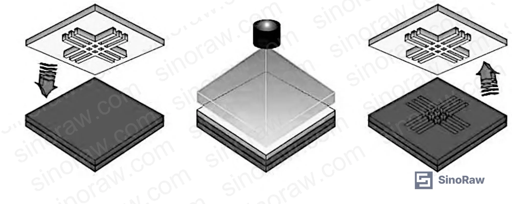
The target specification window for a production-grade UV adhesive in flexible TCF imprinting is tighter than most datasheets suggest. Based on formulation evaluation data from qualified Chinese manufacturers, the performance envelope looks like this:
| Property | Target Specification | Test Reference |
|---|---|---|
| Viscosity | < 1 Pa·s (1,000 mPa·s) | Brookfield, 25°C |
| Cure speed (full depth) | < 10 seconds | 365 nm UV, standard irradiance |
| Refractive index | > 1.51 | ASTM D542 / prism coupler |
| Surface pencil hardness | > H grade | ISO 15184 / GB/T 6739 |
| Adhesion (cross-cut) | Grade 3 (≥75% grid retention) | GB/T 9286-1998 |
| Elongation at break | Flexible range — no delamination under bending | IPC-TM-650 2.4.22 |
| Light transmittance | High visible range (>88% typical) | ASTM D1003 |
A few notes on interpreting this table. The viscosity ceiling of 1 Pa·s is a hard practical limit for imprint processes — above that, you lose pattern fidelity at sub-10 µm feature sizes. The refractive index floor of 1.51 matters because it needs to match or complement the ITO layer’s optical stack; a mismatch introduces interface reflection losses that degrade display contrast ratios. The pencil hardness spec exceeds the nominal H grade — field evaluations on soft-film imprint processes have shown that anything below H results in mold-release damage to the patterned layer during demolding.
Honestly, most procurement teams over-specify cure speed and under-specify refractive index tolerance. A cure time of 8 seconds vs. 6 seconds is irrelevant to yield. A refractive index deviation of ±0.02 from target, on the other hand, can fail an optical stack qualification outright.
The 365 nm cure wavelength is effectively standard for this application. Photoinitiator selection — discussed below — is the primary lever for tuning initiation efficiency at that wavelength. Process lines using different lamp spectra (e.g., broadband mercury vs. LED 365 nm) will see different effective cure depths and surface inhibition behavior, so lamp type must be specified in any qualification protocol.
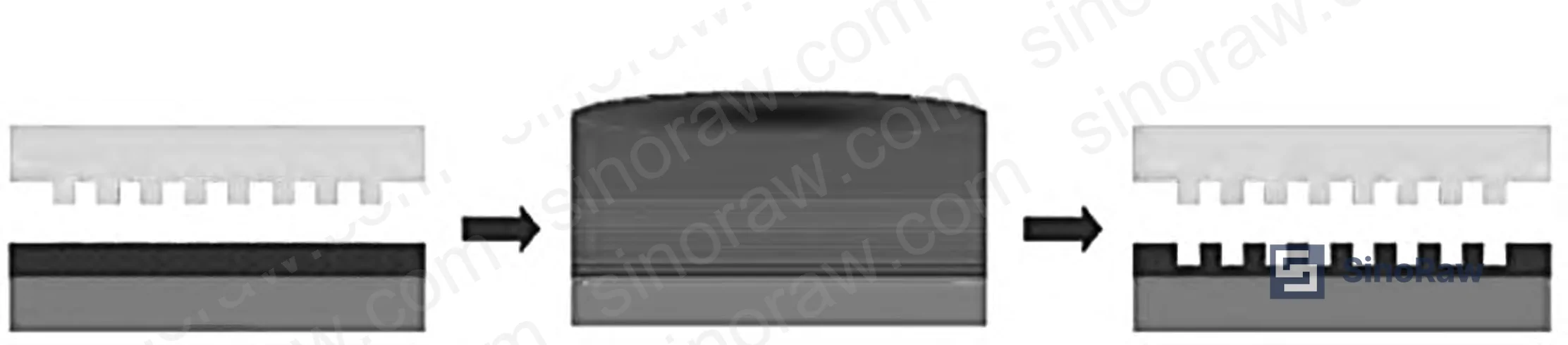
Prepolymer and Monomer Selection: The Formulation Trade-offs That Determine Real Performance #
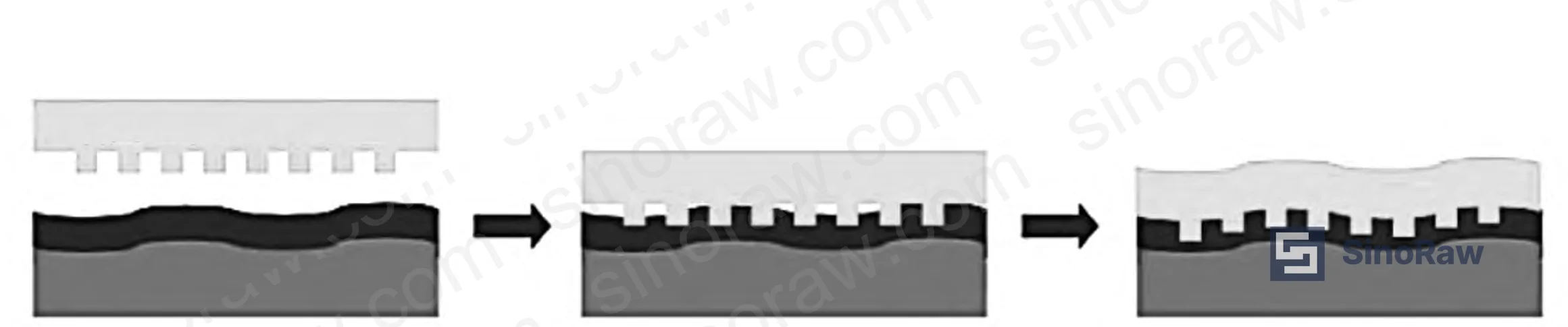
The UV adhesive formulation is built on four components: prepolymer, reactive diluent monomer, photoinitiator, and additive package. How those components interact is where most qualification failures originate.
Prepolymers. The two dominant backbone chemistries are urethane acrylate (UA) and polyester acrylate (PEA). UA prepolymers deliver better elasticity and weathering resistance — critical for TCF applications that undergo repeated flex cycling. PEA prepolymers offer superior optical clarity and long-term adhesion retention, which is why they appear in display-grade formulations requiring extended service life. The molecular weight and soft/hard segment ratio in the prepolymer directly determine final cure properties: light transmittance, elongation, water resistance, and adhesion to ITO and PET surfaces.
New prepolymer structures are entering qualification pipelines — hyperbranched oligomers and radical-cationic hybrid oligomers can offer faster cure response and reduced oxygen inhibition sensitivity. Emerging field evaluations confirm these are beginning to appear in high-volume TCF supply chains, though verified production data from Chinese suppliers is still limited.
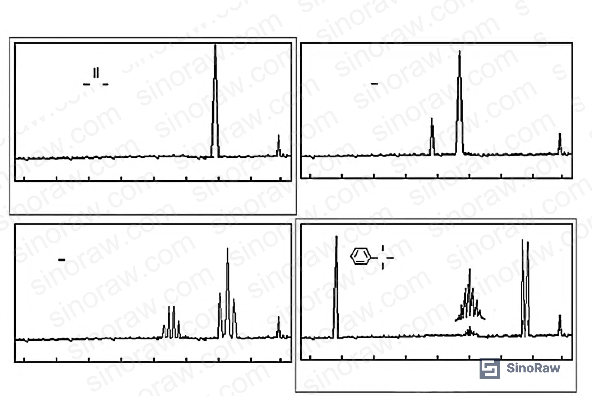
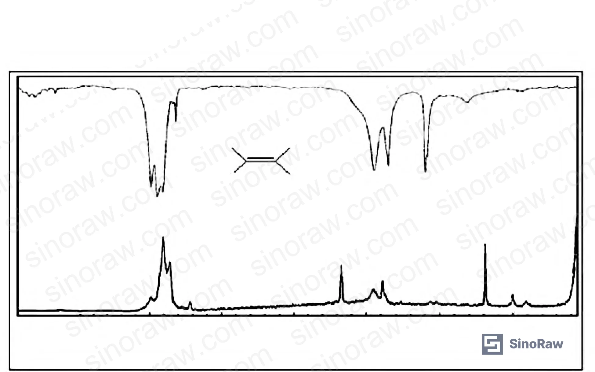
During synthesis characterization, NMR is used to map the backbone chain structure and the soft-segment/hard-segment ratio. GPC (liquid chromatography) confirms molecular weight distribution. IR and Raman spectroscopy cross-verify the NMR output. This analytical sequence is the minimum you should expect a qualified supplier to have completed before presenting a prepolymer candidate.
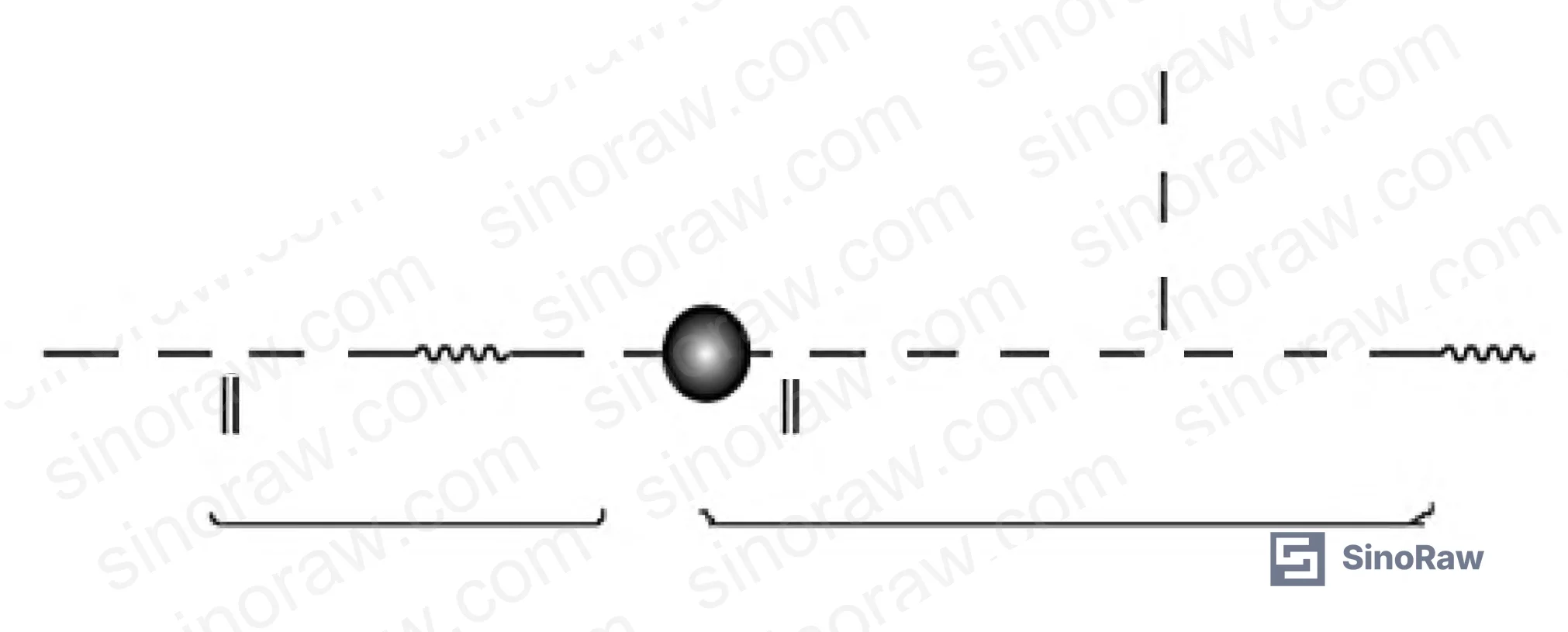
Monomers. Reactive diluent monomers serve a dual function: they reduce viscosity to the processable range and they participate in the crosslinked network after cure. Common choices include methyl methacrylate, isopropyl acrylate, urethane acrylate monomers, and polyether acrylates. The selection involves a genuine three-way conflict between adhesion, hardness, and cure speed — improving one typically degrades another. This is not a solvable problem through single-variable optimization; DOE-based formulation development is the standard approach.
In radical UV systems, the reactive diluents are typically functional (meth)acrylate esters. Cationic UV systems use vinyl ether or epoxide monomers instead, paired with onium salt photoinitiators.
Photoinitiators. For flexible TCF UV adhesives, the primary candidates are:
- Photoinitiator 1173 (2-hydroxy-2-methylpropiophenone): high free-radical efficiency, fast initiation, strong adhesion contribution
- Photoinitiator 184 (1-hydroxycyclohexyl phenyl ketone): good through-cure, widely used in radical systems
- Photoinitiator 907: lower melting point, better miscibility in complex formulations, improved processability
- Benzophenone: cationic initiator type; generates reactive cations rather than free radicals
Matching the photoinitiator absorption peak to the lamp emission spectrum is not optional — it determines effective cure depth, surface cure quality, and residual monomer levels. Current industry practice is to use multiple photoinitiators in combination to broaden spectral coverage and reduce oxygen inhibition sensitivity.
Oxygen Inhibition, Additives, and Filler Selection in TCF UV Adhesive Formulation #
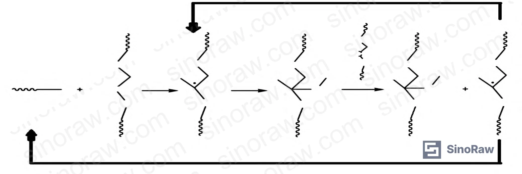
Oxygen inhibition is probably the most under-discussed failure mode in UV adhesive qualification for TCF imprinting. In air, surface radicals are quenched by atmospheric oxygen before network formation is complete, leaving a tacky, under-cured surface layer. For a film that must demolded from a sub-100 nm pattern, surface tack equals pattern damage.
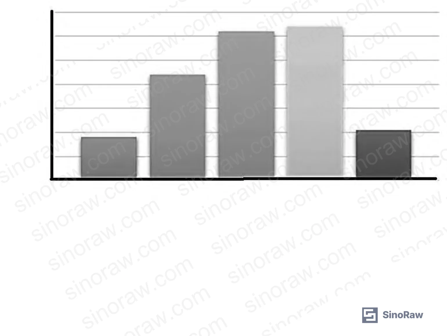
Quantitative data from polymerization rate studies illustrates the problem directly. Under 63 mW/cm² UV irradiance with 1.0 wt% DMPA photoinitiator, the ratio of polymerization rate in air vs. nitrogen varies significantly across monomer types:
- HA (hyaluronic acid derivative): air/N₂ rate ratio ≈ 0.65
- EGMEA: air/N₂ rate ratio ≈ 0.55
- DEGEEA: air/N₂ rate ratio ≈ 0.50
- PPGDA (polypropylene glycol diacrylate): air/N₂ rate ratio ≈ 0.35
- DDA: air/N₂ rate ratio ≈ 0.30
Monomer selection alone can reduce oxygen sensitivity by roughly 2× across this range. The additive package does the rest. Flow-leveling agents improve surface smoothness; defoamers eliminate voids that would otherwise scatter light; plasticizers tune flexibility to match substrate deformation; stabilizers (including inhibitors like hydroquinone or p-methoxyphenol) extend shelf life without premature crosslinking.
Fillers fall into two categories with very different functions in this application:
Conductive fillers — metal powders (Ag, Cu, Ni, Au) and carbon-based materials (graphite, carbon black) — are used where the adhesive layer must contribute to or not impede electrical performance. Silver-coated copper powder and silver-coated SiO₂ are notable here; they improve conductivity while the silver coating provides IR reflectance for thermal management.
Structural/inert fillers — silicates (talc, mica, kaolin), metal oxides (ZnO, Al₂O₃, MgO), sulfates (BaSO₄), and glass microspheres — provide impact resistance, abrasion resistance, and thermal stability without compromising optical transmission.
Most procurement teams don’t realize that standard inorganic filler grades certified for conventional optical coatings are not automatically qualified for nanoimprint molds — particle size distribution matters at sub-micron levels, and agglomeration in the filler can produce mold defects that appear as systematic patterning failures rather than adhesive failures.
Practical Guidance for Buyers #
When qualifying a Chinese UV adhesive supplier for flexible TCF imprinting, request a full formulation characterization package before issuing an RFQ — not just a TDS. That package should include NMR and GPC data on the prepolymer, photoinitiator identity and loading (not just “PI blend”), and polymerization rate data measured in air, not nitrogen. Nitrogen-atmosphere cure data is almost useless for real process qualification.
At SinoRaw, we work as a Guangzhou-based sourcing service connecting overseas procurement engineers with verified Chinese manufacturers of industrial adhesives and specialty chemical materials — our role is to help you structure the RFQ, set the right qualification criteria, and shortlist suppliers who can actually meet them before you commit to sampling. If a supplier cannot provide refractive index test certificates traceable to ASTM D542 or equivalent, and adhesion data cross-referenced to GB/T 9286, treat that as a supplier capability gap, not a documentation issue.
Set your acceptance thresholds before testing, not after. Viscosity < 1 Pa·s, cure time < 10 s, refractive index > 1.51, pencil hardness > H, and adhesion ≥ Grade 3 per cross-cut test are the minimum functional thresholds. Anything negotiated below these values in the TCF imprinting context is a compromise that will show up as yield loss, not just a spec deviation.
For further context on adhesive chemistry selection, see our related guides on specialty polymer systems and silicone and RTV sealant qualification.
Frequently Asked Questions #
Q1: What is the minimum viscosity requirement for a UV adhesive used in flexible TCF nanoimprint lithography, and why does it matter?
Viscosity must stay below 1 Pa·s (1,000 mPa·s) at process temperature. Above that threshold, the adhesive doesn’t conform fully to the mold at room temperature, and pattern fidelity degrades — particularly at feature sizes below 100 nm. Note that viscosity is temperature-sensitive: always specify and measure at your actual process temperature, not at 25°C if your line runs warmer.
Q2: Which photoinitiator works best for 365 nm LED UV cure systems?
Photoinitiator 1173 and PI 184 are the most commonly used in Chinese TCF adhesive formulations for 365 nm systems. PI 907 offers better processability in complex blends. In practice, a combination of two photoinitiators is preferred to broaden spectral response and reduce oxygen inhibition effects near the film surface. The “best” single photoinitiator is less important than matching the overall PI blend absorption profile to your specific lamp emission curve.
Q3: How should buyers interpret GB/T 9286 adhesion Grade 3 in the context of TCF adhesive qualification?
Grade 3 means at least 75% of the cross-cut grid squares remain intact after tape pull. For TCF applications, this is a minimum — not a target. If your substrate is a high-surface-energy PET or treated polyimide film, qualified adhesives should be achieving Grade 1 or 2. Grade 3 on a production-grade TCF substrate warrants further investigation into surface preparation or primer compatibility before accepting the adhesive.
Q4: Can oxygen inhibition be eliminated without nitrogen purging?
Not eliminated — but reduced to manageable levels through formulation. Selecting monomers with lower oxygen sensitivity (e.g., PPGDA-type or EGMEA vs. DDA-type in air/N₂ rate ratio comparisons) and using additives that scavenge surface oxygen radicals can bring the air/N₂ cure rate ratio above 0.5 for most monomers. Nitrogen purging remains the most reliable solution for demanding surface-cure requirements. If your process cannot purge, that constraint must be communicated to the adhesive supplier at the formulation stage.
Q5: What filler types are compatible with high-transmittance UV adhesive for display-grade TCF?
For display-grade applications requiring >88% visible light transmittance, conductive fillers are generally incompatible unless at very low loading levels. Inert inorganic fillers (BaSO₄, glass microspheres at sub-micron d50) can be used at low loadings for mechanical reinforcement. Any filler above 1 µm d50 is a risk for nanoimprint mold contact applications — it will mechanically damage mold features over repeated cycles.
Published by sinoraw.com Technical Team | Request a sourcing quote
Content reviewed by michael.fang | © sinoraw.com — All rights reserved. Unauthorized reproduction prohibited.


