

TL;DR #
After 90 days of immersion in RP-3 aviation kerosene at 95–105°C, uncoated NBR5080 rubber loses 32% of its tensile strength (dropping from 20 MPa to 13 MPa), while PTFE-film-coated specimens retain significantly more integrity, declining only 20% to 16 MPa. For procurement engineers specifying fuel-contact seals in aerospace or industrial turbine applications, this gap is the difference between an acceptable service life and a premature seal failure event. When qualifying Chinese suppliers of PTFE-coated or barrier-film-laminated elastomeric seals, require immersion test data at 100°C for a minimum of 90 days — any supplier who cannot provide this data should be removed from the shortlist.
Overview #

If you are sourcing elastomeric seals or barrier-coated rubber components for fuel systems, high-temperature oil lines, or aerospace hydraulic circuits, the performance gap between standard nitrile rubber and PTFE-film-coated NBR is not a theoretical concern — it is a quantifiable, test-verified failure risk. Research conducted at a Ministry of Education key laboratory specializing in nondestructive testing, in collaboration with aeroengine power control engineering teams, produced a controlled long-duration immersion study comparing uncoated NBR5080 against specimens with double-sided PTFE film bonded via low-temperature plasma (LTP) surface activation and high-temperature adhesive curing. Test specimens were sampled at 0, 1, 4, 7, 15, 30, 60, and 90 days in RP-3 aviation kerosene at a maintained temperature of 95–105°C, with physical, mechanical, micromorphological, and thermal properties tracked at each interval.
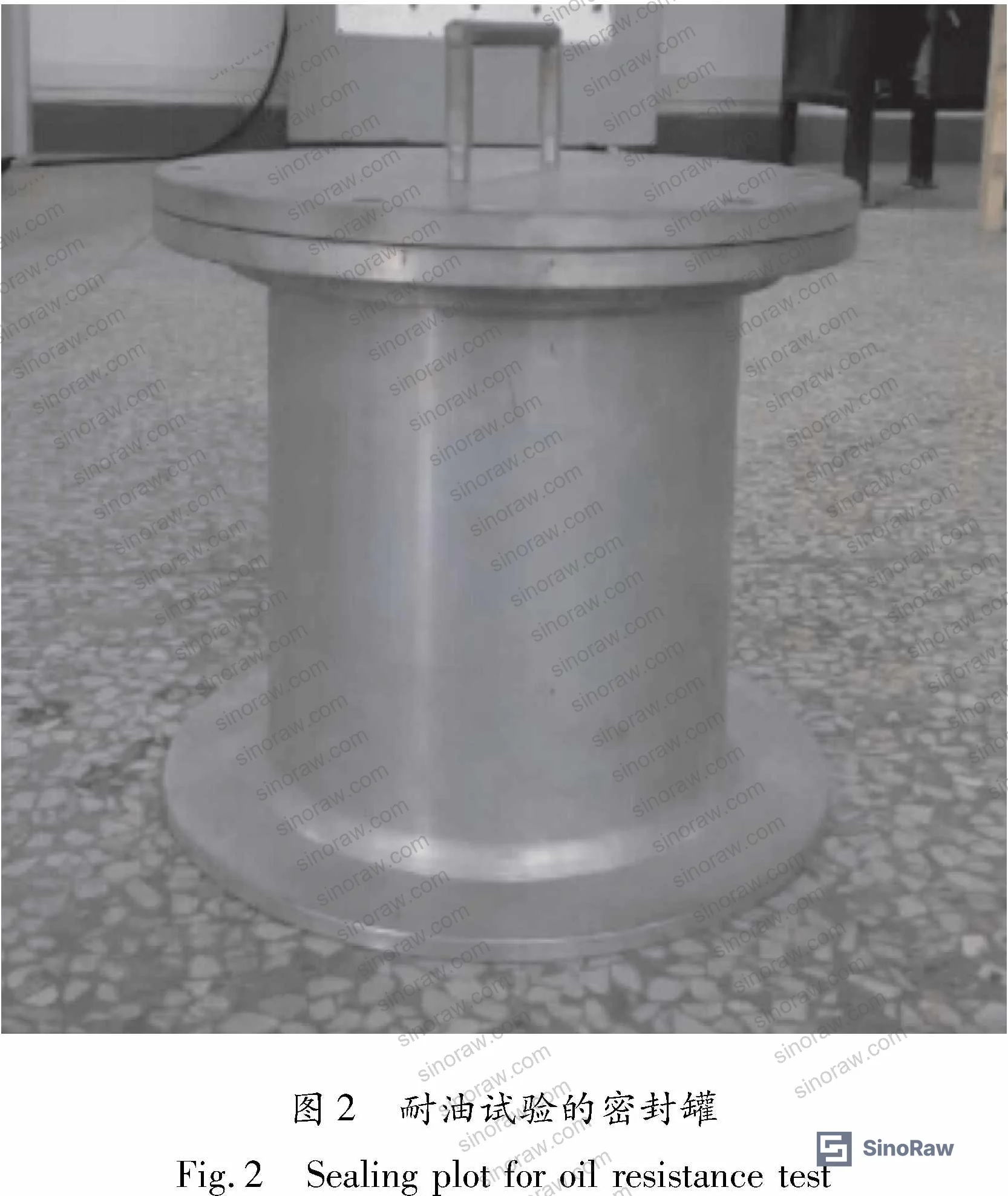
The PTFE film used was 0.10 mm non-oriented film, oxygen-plasma-treated to activate bonding. The NBR5080 substrate was argon-plasma-treated prior to adhesive application. Vulcanization was carried out at 150°C for 30 minutes using a flat-plate press. This is a rigorous qualification methodology — not a simple dip test — and the data it generates is directly applicable to supplier evaluation decisions.
For buyers working with barrier films or polymer-based sealing components in chemically aggressive environments, the test protocol described here provides a practical qualification benchmark. The specialty polymers category on this site covers the upstream material context for both PTFE film and NBR compounds used in these constructions.
PTFE Barrier Film Performance in High-Temperature Fuel Immersion #
This is where the data gets unambiguous. The two-material comparison — uncoated NBR5080 versus PTFE-coated NBR5080 — was run under identical conditions and the divergence in outcomes is stark.
Physical dimensional stability
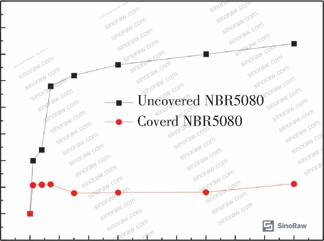
Uncoated NBR5080 exhibited measurable mass gain and dimensional expansion during the early immersion period, consistent with hydrocarbon penetration into the crosslinked rubber network. Mass change stabilized over time but remained elevated. The PTFE-coated specimens showed mass and width variation of approximately ±0.2% throughout the entire 90-day test window — essentially no measurable swelling. This is the PTFE barrier working exactly as intended: the film blocks hydrocarbon molecules from accessing the NBR substrate.

Tensile strength degradation
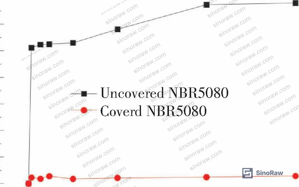
Tensile strength in uncoated specimens fell from an initial 20 MPa to 13 MPa after 90 days — a 32% decline. PTFE-coated specimens dropped from 20 MPa to 16 MPa over the same period — a 20% decline. The absolute difference at 90 days is 3 MPa, which in seal engineering translates directly to compression set margin and burst pressure headroom. If your application has a minimum tensile requirement of 15 MPa for the seal material, the uncoated product fails that threshold by day 90; the coated product does not.
Elongation at break
Elongation at break for uncoated NBR5080 fell continuously from 204% to 117% over 90 days. PTFE-coated specimens declined from 204% to 138% over the same period. The coated material retains 18% more elongation at the endpoint — directly relevant to dynamic sealing applications where elasticity is the failure mode that precedes leakage.
| Property | Uncoated NBR5080 (90 d) | PTFE-Coated NBR5080 (90 d) | Improvement |
|---|---|---|---|
| Tensile Strength | 13 MPa (↓32% from 20 MPa) | 16 MPa (↓20% from 20 MPa) | 12% retained |
| Elongation at Break | 117% (↓from 204%) | 138% (↓from 204%) | +18% retained |
| Mass / Dimensional Change | Measurable swelling | ~±0.2% variation | Stable |
| Surface Morphology at 90 d | Significant voiding, carbon black bloom | Minor surface change | Substantially better |
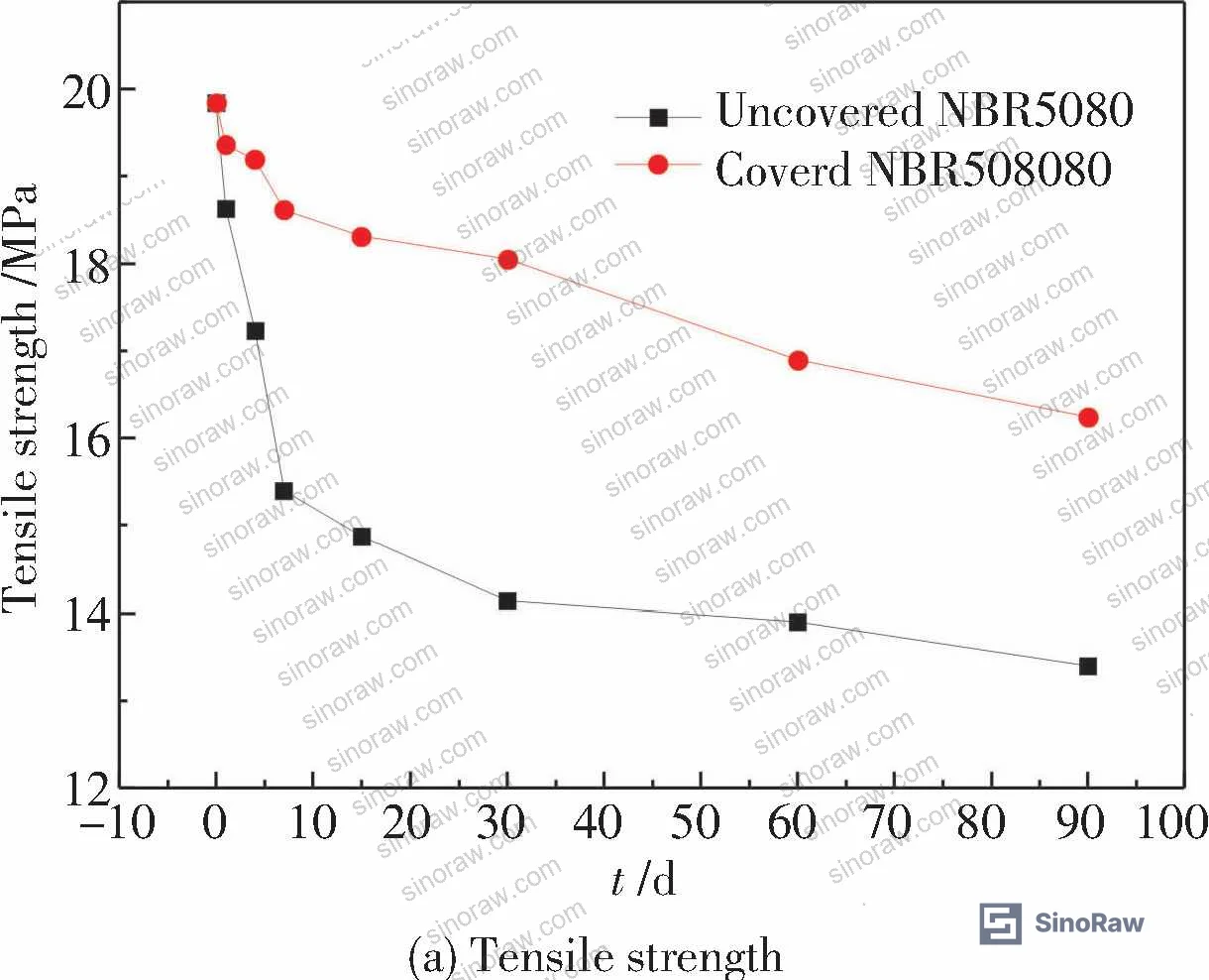
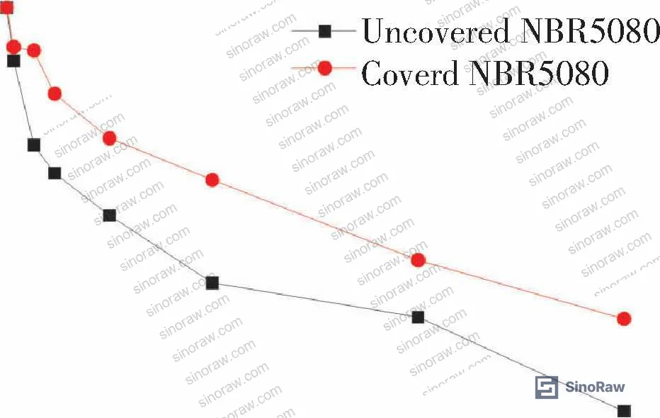
In supplier qualification rounds, if you request a 90-day immersion data sheet and the supplier returns only a 7-day or 30-day result, that is a flag — the degradation curves for uncoated NBR don’t stabilize within 30 days, and the 90-day endpoint is where material compliance decisions need to be made.
Compliance with ASTM D882 Standard Test Method for Tensile Properties of Thin Plastic Sheeting provides a relevant framework for characterizing the film layer’s contribution to mechanical retention, particularly when evaluating the PTFE film component independently before lamination.
Micromorphology and Thermal Degradation of NBR5080 Barrier Composites #
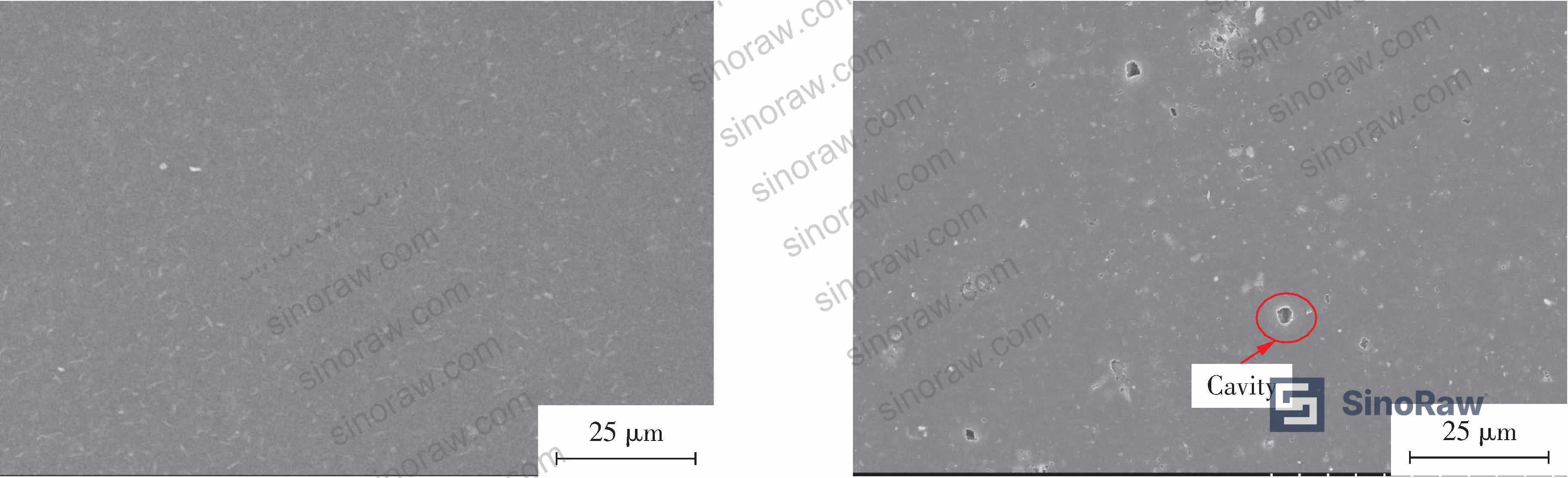
SEM surface and fracture analysis
Before testing, NBR5080 surfaces are relatively smooth with carbon black distributed uniformly throughout the matrix. After 90 days of immersion in RP-3 kerosene, the uncoated specimens show a dramatically different picture: carbon black particles have migrated to the surface and formed visible bloom deposits, voids have appeared at the surface and in fracture sections, and surface roughness is significantly elevated. The mechanism is well-understood — RP-3 kerosene increases the solubility of carbon black reinforcing agents within the NBR matrix, and as the hydrocarbon concentration reaches saturation, carbon black exudes to the surface.
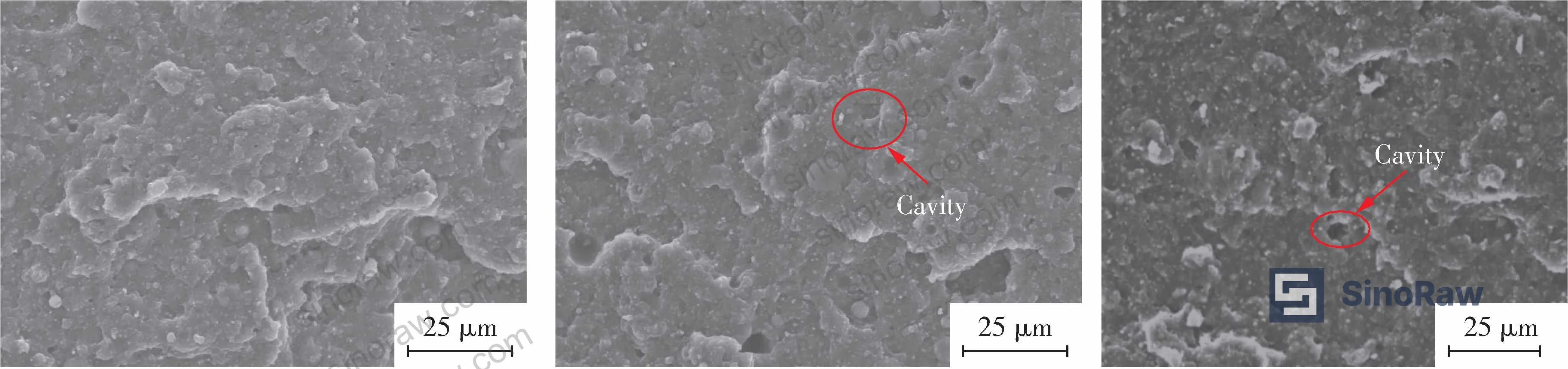
In fracture cross-sections, the uncoated 90-day specimens show prominent voids and increased exudate deposits — consistent with plasticizer and vulcanization aid extraction (zinc stearate, thiuram sulfur compounds, and ester plasticizers all dissolving into the kerosene). The PTFE-coated specimens at 90 days show only minor voiding in fracture sections — substantially less than uncoated equivalents and consistent with the mechanical data.
Thermal analysis (TGA/DTG)
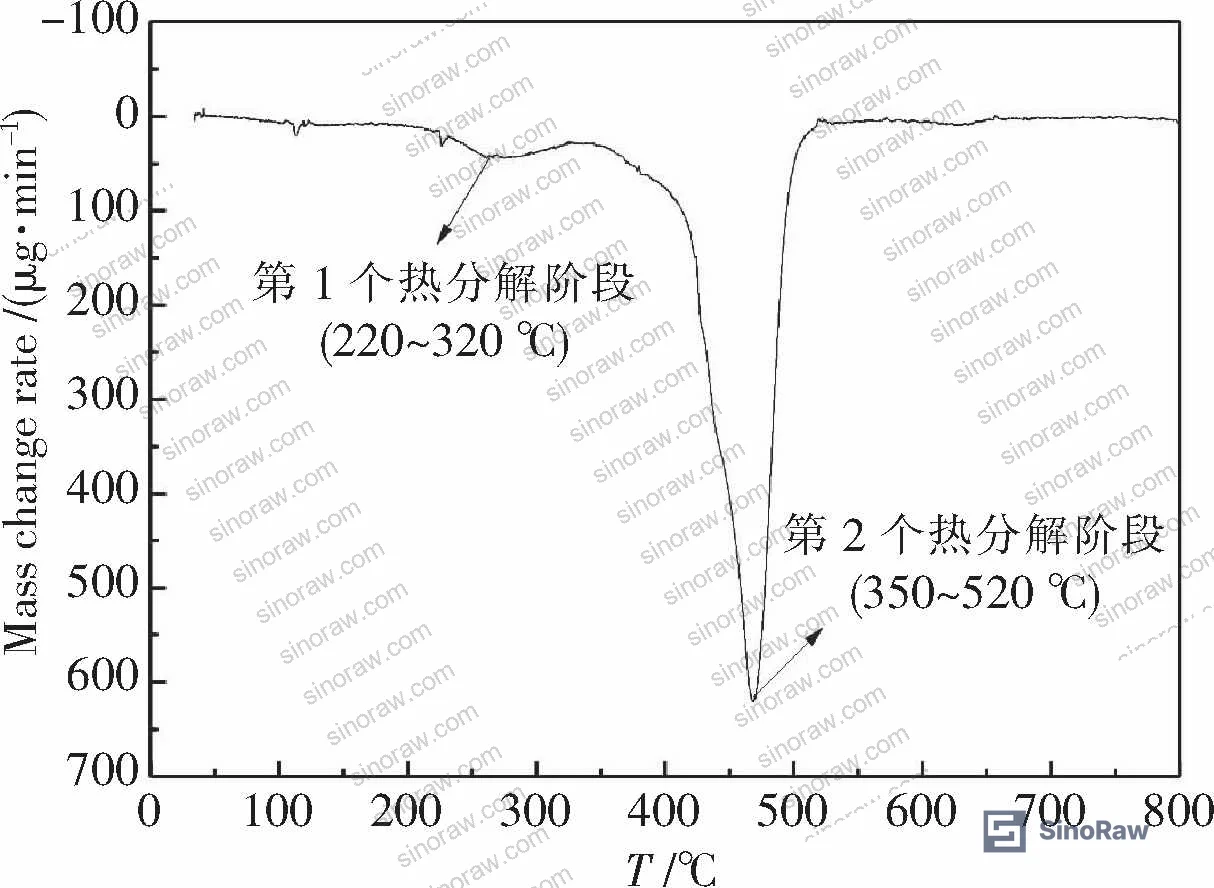
This is where the extraction mechanism gets confirmed by thermal data. Original NBR5080 shows two distinct thermal decomposition stages: a first stage at 220–320°C attributable to vulcanization aids and compounding agents (zinc stearate, thiuram, plasticizers), and a second stage at 350–520°C corresponding to the rubber polymer backbone.
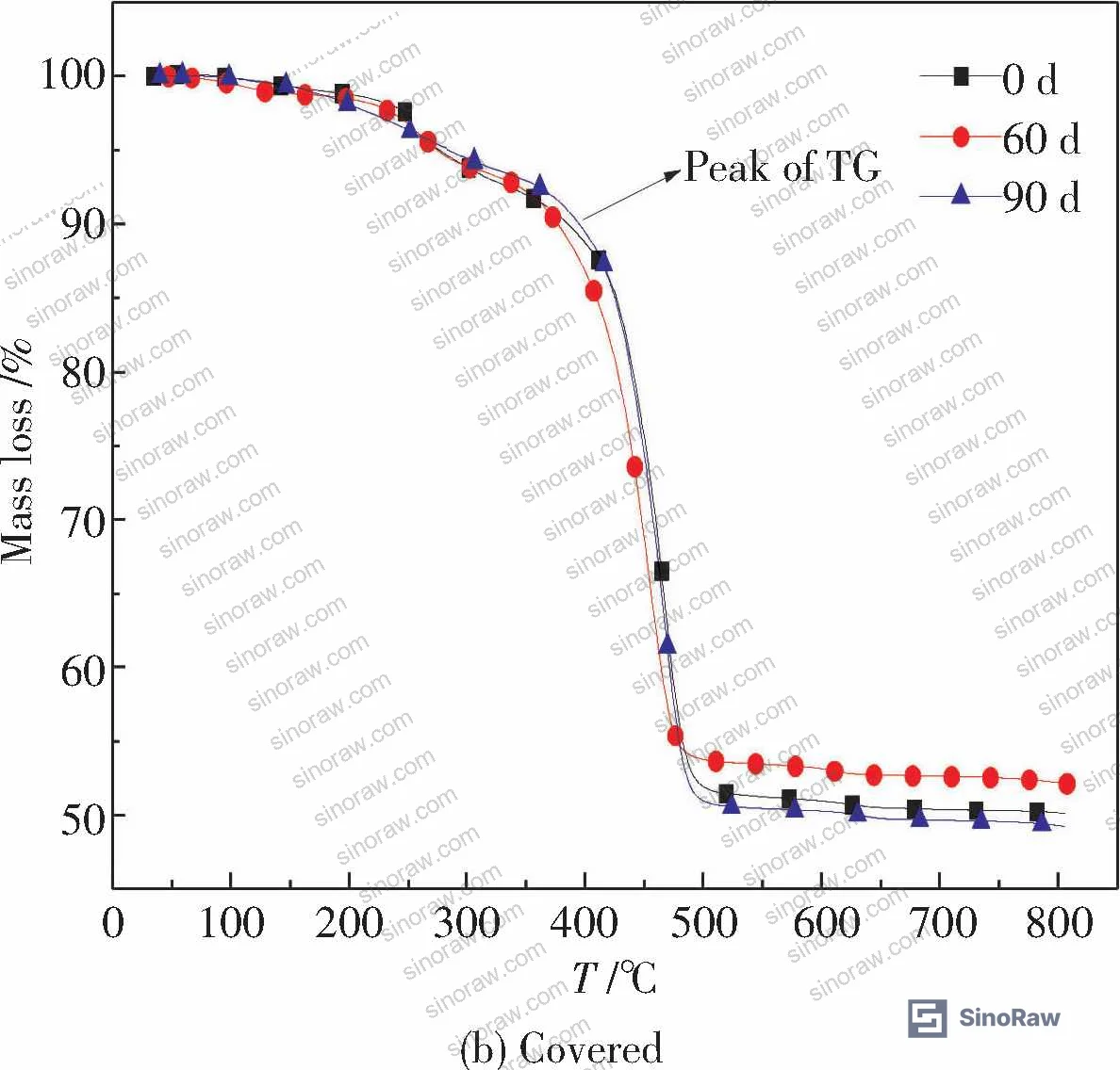
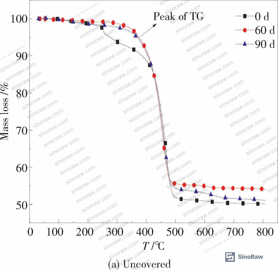
After kerosene immersion — whether at 60 days or 90 days — the first decomposition peak (220–320°C) disappears entirely in both coated and uncoated specimens. The compounding agents have leached out into the kerosene. Only the second decomposition event at 350–520°C remains.
| Sample Condition | Initial Decomp. Temp. (°C) | Max Decomp. Temp. (°C) | Final Temp. (°C) | Mass Loss (%) |
|---|---|---|---|---|
| Original NBR5080 | 338.5 | 468.1 | 518.7 | 49.8 |
| Uncoated, 60 d | 322.8 | 460.3 | 514.7 | 46.0 |
| Uncoated, 90 d | 336.4 | 461.5 | 514.8 | 49.0 |
| Coated, 60 d | 328.7 | 460.5 | 516.3 | 50.2 |
| Coated, 90 d | 324.1 | 455.1 | 513.6 | 48.1 |
Most procurement teams don’t realize that the disappearance of the low-temperature decomposition peak in post-immersion TGA data is actually a diagnostic tool — it confirms compounding agent leaching has occurred, and this correlates directly with the void formation and bloom seen in SEM. If you’re evaluating rubber seals that have been in service and you have access to a TGA instrument during incoming inspection, this signature is worth knowing.
The REACH Regulation (EC) No 1907/2006 is relevant here: ester plasticizers and zinc-based compounding agents that leach from uncoated NBR into fluid systems need to be assessed for their downstream chemical impact, particularly in closed-loop hydraulic or fuel recirculation systems.
Practical Guidance for Buyers #
Honestly, most buyers over-specify the base rubber compound when they should be specifying the barrier coating architecture. An NBR5080 compound with no surface treatment will fail a 90-day fuel resistance test in any application running above 90°C — that’s not a hypothesis, it’s what the immersion data shows. The question isn’t whether to use a PTFE film barrier layer; it’s whether the supplier’s bonding process is robust enough to keep that layer intact under thermal cycling and mechanical flex.
The critical process variables are the LTP surface activation step and the adhesive cure cycle. A supplier who is simply laminating PTFE film with a room-temperature adhesive is not producing the same component as one using plasma activation followed by a 150°C, 30-minute vulcanization cure. These are not equivalent. Ask specifically about the surface treatment method and adhesive system — if they can’t answer with specific parameters, they haven’t done it properly.
For dimensional and weight stability requirements, the ±0.2% mass change criterion for PTFE-coated specimens is a defensible acceptance threshold for fuel-contact seal qualification. For tensile retention, a minimum of 16 MPa after 90-day immersion at 100°C in RP-3 or equivalent hydrocarbon fluid represents the PTFE-coated performance baseline documented in this evaluation.
At sinoraw.com, our team works with procurement engineers and sourcing managers to identify and pre-screen Chinese manufacturers of barrier-coated rubber components and PTFE film laminates — so you’re evaluating suppliers who already understand the technical requirements, not starting from scratch. Compliance with ISO 9001:2015 Quality management systems is a baseline expectation; the technical differentiation happens in process documentation depth and immersion test data availability.
For additional context on film-based barrier constructions used in chemically demanding environments, the barrier films section covers the broader material landscape.
Need help identifying qualified suppliers for PTFE-coated NBR seals or barrier film laminates? Talk to our sourcing team →
Supplier Qualification Questions #
- Can you provide 90-day immersion test data for your PTFE-coated NBR product in RP-3 or equivalent hydrocarbon kerosene at 95–105°C, showing tensile strength retention above 16 MPa and elongation at break above 130%?
- What is the PTFE film thickness used in your standard barrier coating construction, and is it non-oriented film at 0.10 mm nominal — or do you use a different specification, and why?
- What surface activation method do you use prior to PTFE-to-NBR bonding — specifically, do you use low-temperature plasma treatment (LTP), and if so, what gas atmosphere (O₂ for PTFE, Ar for NBR) and what is the maximum elapsed time between plasma treatment and adhesive application before surface energy degrades?
- What is your vulcanization cure cycle for the PTFE-NBR composite — specifically the temperature, time, and press pressure — and can you provide cure cycle documentation showing that the bonding step reaches 150°C for at least 30 minutes?
- Can you provide TGA or DTG data showing the two-stage thermal decomposition profile of your base NBR5080 compound (Stage 1: 220–320°C; Stage 2: 350–520°C), confirming correct compounding agent content prior to immersion exposure?
Sourcing Checklist #
- ☐ Supplier provides 90-day RP-3 kerosene immersion test data at 95–105°C with documented tensile strength retention ≥16 MPa for PTFE-coated specimens
- ☐ Elongation at break retention after 90-day immersion is confirmed ≥130% (coated specimen baseline per test data is 138%)
- ☐ PTFE film is specified as non-oriented, 0.10 mm nominal thickness, with oxygen plasma surface activation prior to bonding
- ☐ Mass and dimensional change of coated specimens after full immersion period is documented at ≤±0.5% (tested baseline is ~±0.2%)
- ☐ Adhesive bonding process uses a high-temperature cure at ≥150°C for ≥30 minutes under press vulcanization conditions — room-temperature adhesive lamination is not acceptable
- ☐ TGA profile of base NBR compound shows two-stage decomposition: first stage 220–320°C (compounding agents), second stage 350–520°C (polymer backbone)
- ☐ Supplier holds ISO 9001:2015 certification and can produce process records for plasma treatment, adhesive application, and cure cycle
- ☐ SEM or equivalent surface characterization data available for qualification batch showing no pre-immersion surface defects or carbon black bloom
Key Specifications Table #
| Parameter | Recommended Value | Verification Method |
|---|---|---|
| Tensile strength after 90-day RP-3 immersion at 100°C | ≥16 MPa (PTFE-coated) | GB/T 528-2009 tensile test, UTM load frame |
| Elongation at break after 90-day immersion | ≥130% (PTFE-coated) | GB/T 528-2009 tensile test at each sampling interval |
| Mass and dimensional change after full immersion | ≤±0.5% | Electronic balance + caliper measurement per GB/T 1690-2010 |
| PTFE film thickness | 0.10 mm nominal, non-oriented | Micrometer or cross-section SEM measurement |
| Vulcanization cure temperature / time | 150°C / 30 min minimum | Cure cycle process record, thermocouple-verified press data |
| First-stage TGA decomposition peak | 220–320°C present in pre-immersion specimen | TGA/DTG analysis (Diamond TG/DTA or equivalent) |
| Second-stage thermal decomposition range | 350–520°C, mass loss ~49% | TGA analysis; loss deviation >5% indicates compounding inconsistency |
Can’t find a supplier meeting these specs? Submit your requirements and we’ll match you within 48 hours.
References #
Data source: PTFE Film Barrier Coating for Enhanced High-Temperature Aviation Kerosene Resistance of Nitrile Butadiene Rubber Seals, T.-X. Zhou et al., Polymer Testing, 2025
Frequently Asked Questions #
Why does the PTFE coating prevent swelling when standard NBR5080 swells significantly in aviation kerosene?
PTFE has one of the lowest surface energies of any solid material and is chemically inert to essentially all hydrocarbon fluids. When properly bonded to the NBR substrate via plasma-activated surfaces, it acts as a physical barrier that blocks kerosene molecules from penetrating to the rubber beneath. Uncoated NBR5080 absorbs hydrocarbon molecules directly into its crosslinked network, causing the observed mass gain and dimensional expansion. The PTFE film doesn’t eliminate all degradation — it reduces it substantially, as the 20% tensile decline in coated specimens still confirms some long-term exposure effect — but the swelling mechanism is effectively blocked.
What happens to compounding agents like zinc stearate and plasticizers in extended fuel immersion, and why does it matter?
These agents leach out into the fuel. The TGA evidence for this is clear: the first thermal decomposition peak at 220–320°C, which corresponds to zinc stearate, thiuram vulcanization agents, and ester plasticizers, disappears entirely in both coated and uncoated specimens after 60 and 90 days of immersion. In uncoated specimens, this leaching is accompanied by void formation and carbon black migration visible in SEM fracture sections. The practical implication is that the mechanical properties of the seal continue degrading even after the initial swelling stabilizes — and the PTFE coating partially limits this extraction pathway.
Is the 32% tensile strength drop in uncoated NBR5080 a failure by any standard specification?
That depends on the application’s minimum tensile requirement. If your seal specification requires ≥15 MPa tensile strength, the uncoated NBR5080 at 13 MPa after 90 days fails that requirement. The PTFE-coated specimen at 16 MPa passes. Many standard aerospace seal specifications do set minimum tensile thresholds in the 14–18 MPa range for nitrile compounds, so this is not a hypothetical concern.
Can the LTP plasma treatment process be skipped if a strong structural adhesive is used instead?
No. PTFE has extremely low surface energy, which is why conventional adhesives don’t bond to it reliably. The oxygen plasma treatment creates reactive polar groups on the PTFE surface that enable adhesive mechanical and chemical anchoring. Without plasma activation, the PTFE film will delaminate under thermal cycling or mechanical stress — the barrier protection is only as good as the bond integrity. Suppliers who cannot describe their plasma treatment parameters in detail are likely producing components with inadequate adhesion.
What is the significance of the ±0.2% mass stability figure for PTFE-coated specimens?
It is the quantitative proof that the PTFE barrier is working. Dimensional and mass stability directly below ±0.5% over a 90-day high-temperature fuel immersion is the acceptance criterion that separates a functional barrier construction from one that is merely better than uncoated rubber. For procurement, this figure can be written directly into a supplier acceptance test requirement under the applicable rubber fluid resistance standard, and any batch showing mass change outside this range should trigger a non-conformance review.
Published by sinoraw.com Technical Team | Request a sourcing quote


