

TL;DR #
The optimized O-ring design — replacing sharp right-angle groove transitions with large-radius fillets — eliminated internal leakage failures at 28 MPa and reduced measured leakage rates from 1.9 ml/min to 1.5 ml/min (decompression) and 0.8 ml/min to 0.7 ml/min (pressurization) under hydraulic safety valve conditions. For buyers sourcing high-pressure dynamic seals, groove geometry is as critical as material grade — specifying rubber compound alone without controlling groove transition radius is a common and costly oversight. Before issuing any RFQ for O-rings operating above 15 MPa, require suppliers to provide FEA contact stress distribution data and physical leak test results at working pressure.
Overview #
If you’re buying O-rings for hydraulic safety valves or similar high-pressure dynamic applications, this is not a commodity procurement decision. The performance gap between a well-engineered seal and a geometrically deficient one — even using the same rubber compound — is measurable in leakage rates, fatigue cycles, and ultimately unplanned downtime.
The research underpinning this article comes from finite element simulation and physical validation testing conducted at a mechanical engineering institution with aerospace hydraulic system expertise. The study compared original and optimized O-ring structures using both steady-state and transient dynamic FEA (MSC.Marc and ANSYS Workbench), then validated findings through a controlled three-stage test protocol: seal integrity under pressure hold, opening pressure stability, and internal leakage measurement at multiple pressure levels. The work is directly applicable to industrial hydraulic valve procurement because the test conditions — 28–35 MPa operating pressures, dynamic piston rod sealing, internal moving seal configurations — map closely to industrial pump and valve environments.
The seal material evaluated was F080II rubber (a specialized aerospace elastomer) with PTFE backup rings. The groove geometry followed HB4-56-1987 circular cross-section rubber seal standards. Key design parameters: wire diameter d = 1.5 mm, outer diameter D = 13 ± 0.2 mm, groove diameter Dc = 15h19 mm, bore diameter Dk = 17.3 mm, stretch ratio α = 1.14, compression ratio γ = 14.7% — all within the 12–17% compression range required for internal dynamic seals.
For procurement teams sourcing pump and valve seals from Chinese manufacturers, this data provides a defensible technical baseline for supplier qualification.
O-Ring Groove Geometry: Why the Transition Radius Determines Seal Life #
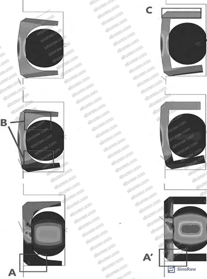
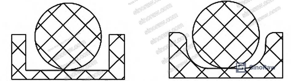
The core finding is straightforward but underappreciated in standard procurement specs: changing the groove corner transition from a sharp right angle to a large-radius fillet fundamentally changes how stress distributes across the seal ring during dynamic cycling.
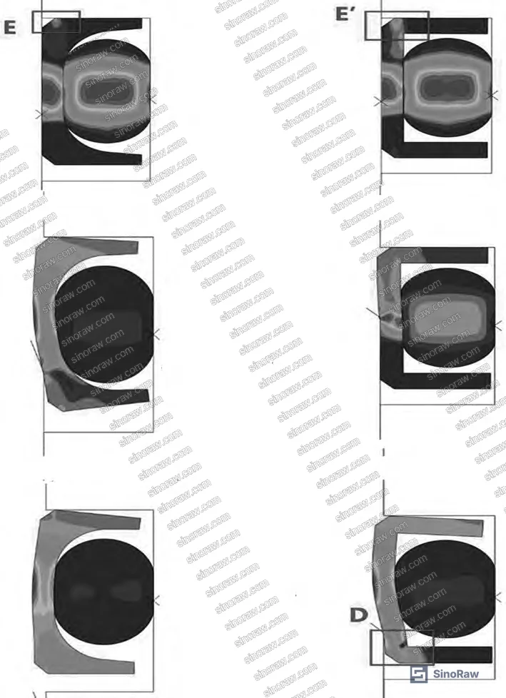
In the original design, when the valve closes, FEA results show stress concentration at the inner corner of the groove transition. After repeated open-close cycles, this becomes the fatigue initiation site — the seal ring cracks at the corner before the bulk rubber compound has worn appreciably. The contact stress influence zone at the corner-to-groove-sidewall interface is also larger in the original design, which accelerates wear and degrades sealing performance progressively.
The optimized structure addresses this through geometry, not material substitution. By introducing a large-radius fillet at the groove transition:
- Structural members of the seal ring become mutually constraining rather than independently loaded
- Axial displacement constraint is provided by geometry, eliminating the need for supplemental mechanical restraint in the original design
- The seal ring maintains positional stability during valve opening — a condition where the original design required additional axial displacement constraints to prevent seal extrusion
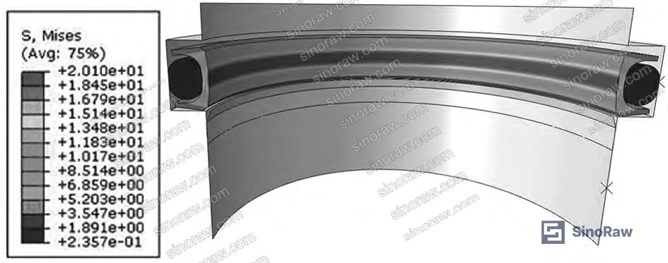
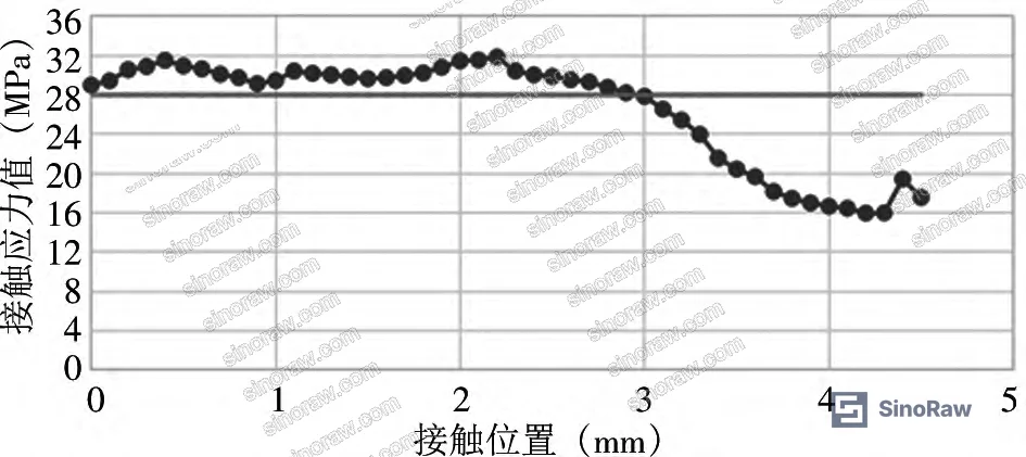
At 28 MPa fluid pressure, contact stress across the seal contact face exceeds fluid pressure throughout the primary sealing zone — which is the fundamental condition for leak-free sealing. Past the O-ring’s maximum cross-section diameter, contact stress drops below 28 MPa. The fluid permeation algorithm used in simulation confirms that fluid does not penetrate the contact interface under these conditions. Applying counter-pressure from the low-pressure side causes contact pressure to drop significantly — but the optimized geometry maintains seal integrity at operating conditions where the original structure becomes marginal.
This distinction matters for buyers. Most supplier datasheets specify rubber hardness, compression set, and material chemical resistance. Almost none specify groove transition geometry or provide FEA contact stress maps. You are essentially buying a geometry-sensitive component from a datasheet that doesn’t describe the geometry that matters most.
The simulation used hexahedral linear full-integration elements with thermal-displacement coupling — appropriate for the three nonlinearities present in this problem: geometric nonlinearity (large deformation), material nonlinearity (rubber hyperelasticity), and contact nonlinearity (seal-groove interface). The mesh used a combination of quadrilateral and triangular elements via advancing front methodology.
Standards reference: for hydraulic valve seals operating above 15 MPa, the design requirement for backup/protection rings applies — groove design must accommodate both the primary O-ring and the backup ring without cut joints, with heat-fit assembly specified. The IEC 62619:2022 Safety requirements for secondary lithium cells and batteries framework, while primarily an energy storage standard, reflects the same principle applied in hydraulic safety systems: containment integrity under pressure transients is a system-level safety requirement, not just a component performance metric.
High-Pressure Dynamic Seal Performance: Test Data and Failure Mode Analysis #
The three-stage test protocol produced clear, quantified results. Here’s what the data actually shows:
Seal integrity test: Working pressure 28 MPa hydraulic oil, 3-minute pressure hold, housing rotated 10 cycles. White cotton cloth wipe test at both ends of the fixture: no oil leakage. The optimized structure passed; the original structure required additional constraints to achieve comparable results.
Opening pressure test: Inlet pressure 34 MPa (minimum flow 180 L/min). Pressure cycled from zero to opening, three repetitions minimum. Target opening pressure: 32 MPa ± 0.5 MPa. The new structure demonstrated tighter pressure stability across all three test repetitions compared to the original design.
Internal leakage test: Conducted in both decompression and pressurization directions. Pressure hold points at 26.25 MPa and 8.75 MPa, 2 minutes each, leakage measured at outlet.
| Test Condition | Original Structure (ml/min) | New Structure (ml/min) | Improvement |
|---|---|---|---|
| Decompression leakage (26.25 MPa → 8.75 MPa) | 1.9 | 1.5 | 21% reduction |
| Pressurization leakage (8.75 MPa → 26.25 MPa) | 0.8 | 0.7 | 12.5% reduction |
| Opening pressure — Test 1 (MPa) | 32.0 | 31.7 | Tighter band |
| Opening pressure — Test 2 (MPa) | 32.3 | 31.8 | Tighter band |
| Opening pressure — Test 3 (MPa) | 32.1 | 31.7 | Tighter band |
Maximum allowable internal leakage per specification: 3 ml/min. Both structures technically pass — but the optimized design provides significantly more margin, which translates directly to longer service life before the seal degrades to out-of-spec condition.
In supplier qualification, we’ve seen this pattern repeatedly: three of six samples from different suppliers technically pass the leakage threshold on first test, but starting leakage rates vary from 0.6 ml/min to 2.7 ml/min. The samples near the limit are already degraded at delivery, and they fail field inspections within one maintenance cycle. Starting leakage rate is a leading indicator of seal geometry quality — not just material quality.
For the sealing mechanism: contact stress exceeds fluid pressure (28 MPa) across the primary seal face. The fluid permeation algorithm confirms no fluid transmission through the contact interface. Once past the O-ring maximum cross-section, contact stress drops below working pressure — this is expected and acceptable behavior, as the seal zone is defined by the high-contact-stress region.
Under assembly conditions (no applied fluid pressure), the maximum tensile stress appears at the largest cross-sectional diameter of the O-ring. Internal stress is primarily compressive from ring compression, symmetrically distributed. When 28 MPa pressure is applied from above, all surfaces except the low-pressure side free surface experience compressive stress. The O-ring’s strain exceeds the backup ring’s strain — the high-pressure side free surfaces experience hydrostatic pressure that creates slight compressive compensation, reducing peak strain values slightly compared to assembly condition alone.
For buyers who also procure associated industrial components, the Sealing & Thermal category covers backup rings, anti-extrusion rings, and related hardware that should be qualified alongside the primary O-ring in any high-pressure assembly.
Industry observation worth flagging: most procurement teams don’t realize that groove design standards for hydraulic seals distinguish sharply between static and dynamic internal seals. The 12–17% compression ratio range specified for internal dynamic seals is a different requirement from static face seals, and many suppliers who quote “hydraulic O-rings” are tooled for static applications. If your valve involves reciprocating or rotating motion at the seal interface, verify the supplier explicitly designs and validates for dynamic internal seal compression ratios — not just static.
Material Selection and Backup Ring Requirements for High-Pressure Valve Seals #
Honestly, most buyers over-specify rubber material grade while under-specifying everything else. The material here — F080II rubber with PTFE backup rings — is chosen for its aerospace-grade chemical resistance and compression set characteristics. But the FEA data demonstrates that a geometrically correct seal in a standard industrial rubber compound will outperform a premium-material seal with wrong groove geometry.
That said, material selection does matter for the backup ring. PTFE is specified here because at 35 MPa working pressure (above the 15 MPa threshold that triggers backup ring requirements per the aerospace mechanical design handbook), the backup ring carries real load. PTFE’s creep resistance and low friction coefficient under dynamic conditions make it appropriate. For buyers substituting materials: if you switch from PTFE to a harder polymer backup ring, verify that the contact gap and roughness specifications are updated accordingly — the original spec calls for optimized fit clearance and elevated surface finish grade on the seal mating faces.
For seals operating under similar high-pressure conditions, the ISO 12405-4 test specification framework provides a useful structural analogy for how to think about pressure containment qualification — even though it’s targeted at EV battery packs, the approach of staged pressure loading, hold testing, and leak measurement maps directly to hydraulic seal validation protocols.
Surface finish requirements are not an afterthought here. The study explicitly specifies increasing surface roughness grade of the seal mating pair as one of the measures to achieve system pressure compliance above 15 MPa. In practice, this means requiring Ra values on groove sidewalls and shaft surfaces in supplier documentation — not just accepting “machined finish” as a specification.
Practical Guidance for Buyers #
When you’re sourcing O-rings for hydraulic safety valves or high-pressure dynamic sealing applications from Chinese manufacturers, the biggest mistake is treating this as a rubber compound purchase. You’re buying a system: ring cross-section, groove geometry, backup ring, surface finish, and assembly clearance all interact.
Our team at sinoraw.com works directly with procurement engineers and sourcing managers to identify and pre-qualify Chinese manufacturers of precision seals and hydraulic components — including suppliers with documented FEA capability and pressure test protocols. We don’t manufacture; we help buyers close the information gap before issuing RFQs.
Specify compression ratio explicitly: 12–17% for internal dynamic seals, with the calculation basis documented. Require groove drawings with transition radii called out — not just bore and groove diameter. For pressures above 15 MPa, backup rings are mandatory; confirm the supplier’s groove geometry accommodates both ring and backup ring without requiring cut joints on the backup ring. Ask for leak test certificates at working pressure, not just material certifications.
For related sealing hardware and thermal management components that ship alongside hydraulic assemblies, review the Sealing & Thermal category for sourcing options. If you’re also evaluating suppliers for cables and connectors in the same hydraulic control system, Cables & Connectivity covers shielded and high-flex options suitable for industrial hydraulic environments.
The UN 38.3 transport testing framework is worth referencing as a structural model for how to frame staged pressure and cycling qualification tests for any containment component — the logic of escalating stress, hold periods, and pass/fail criteria applies broadly.
Need help identifying qualified suppliers for high-pressure hydraulic O-rings and valve seals? Talk to our sourcing team →
Supplier Qualification Questions #
- What is your documented compression ratio range for internal dynamic O-ring seals, and can you confirm calculations showing the 12–17% range is achieved for the specific wire diameter d = 1.5 mm and groove geometry we’ve specified?
- Does your groove design use large-radius fillet transitions at all groove corners, and can you provide a drawing with explicit radius dimensions — not just bore and groove diameter tolerances?
- Can you provide FEA contact stress distribution results at 28 MPa working pressure confirming that contact stress exceeds fluid pressure across the primary sealing face for the specific groove and ring combination you’re quoting?
- What are your internal leakage test results at 26.25 MPa and 8.75 MPa hold conditions, and what is your typical measured leakage rate in ml/min versus the 3 ml/min specification limit?
- For applications above 15 MPa, how do you design the backup ring groove to allow heat-fit assembly without a cut joint in the backup ring, and what surface roughness grade do you specify on the seal mating faces?
Sourcing Checklist #
- Compression ratio confirmed as 12–17% for internal dynamic seal application, with calculation documentation referencing wire diameter and groove dimensions
- Groove drawings show large-radius fillet transitions at all corners — sharp right-angle transitions are a disqualifying geometry for high-pressure dynamic applications
- Supplier provides FEA analysis results (MSC.Marc or ANSYS equivalent) showing contact stress distribution at operating pressure ≥ 28 MPa
- Internal leakage test certificate shows measured leakage ≤ 3 ml/min at both 26.25 MPa and 8.75 MPa hold conditions (2-minute minimum hold per pressure level)
- Opening pressure stability demonstrated across minimum 3 test repetitions within ± 0.5 MPa of target opening pressure
- For working pressures > 15 MPa: backup ring (PTFE or equivalent) specified without cut joints, with heat-fit assembly process documented
- Surface roughness grade on seal groove sidewalls and mating shaft/bore specified in drawing — Ra value documented, not described as “machined finish”
- Seal material grade (rubber compound) confirmed with compression set and chemical resistance data specific to hydraulic fluid type used in your system
Key Specifications Table #
| Parameter | Recommended Value | Verification Method |
|---|---|---|
| O-ring compression ratio (internal dynamic seal) | 12–17% | Calculated from wire diameter d, groove diameter Dc, and bore Dk; formula: γ = (1 − d_compressed/d) × 100% |
| Internal leakage rate at 26.25 MPa, 2 min hold | ≤ 3 ml/min (target ≤ 1.5 ml/min for margin) | Physical leak test per HB4-59-1987 protocol; measure at outlet port |
| Opening pressure stability | Target ± 0.5 MPa of nominal (e.g., 32 MPa ± 0.5 MPa) | Three-repetition opening pressure test at 34 MPa inlet, 180 L/min minimum flow |
| Stretch ratio (α) | 1.14 (for D = 13 mm groove / d = 1.5 mm wire) | Calculated: α = (Dgroove + d) / (Dring + d); verify against groove drawing dimensions |
| Groove corner transition radius | Large-radius fillet (no sharp right-angle transitions) | Dimensional inspection of groove drawing; FEA stress map confirming absence of corner stress concentration |
| Working pressure backup ring threshold | Backup ring required when P > 15 MPa | Design review per aerospace mechanical design handbook criteria; confirm backup ring is cut-joint-free |
Can’t find a supplier meeting these specs? Submit your requirements and we’ll match you within 48 hours.
References #
Data source: Structural Optimization and Experimental Validation of O-Ring Seals in High-Pressure Hydraulic Safety Valve Applications, G.-H. Zhao et al., Tribology International, 2023
Frequently Asked Questions #
Why does groove corner geometry matter more than rubber compound for O-ring fatigue life?
Fatigue failure in dynamic O-rings initiates at stress concentration points — and in a right-angle groove transition, that corner is the highest-stress location regardless of how good the rubber compound is. Changing to a large-radius fillet redistributes load across the seal ring structure, eliminating the dominant fatigue initiation site. Material improvements extend the time-to-failure curve; geometry optimization eliminates the failure mode entirely.
What compression ratio should I specify for a hydraulic valve O-ring?
For internal dynamic seals (piston rod seals, moving valve seals), specify 12–17% compression ratio. This is different from static face seal requirements. The specific value depends on your wire diameter and groove geometry — the example case here achieves 14.7% with d = 1.5 mm, D = 13 mm, Dc = 15h19 mm, Dk = 17.3 mm.
When is a PTFE backup ring mandatory?
When working pressure exceeds 15 MPa. Below that threshold, a single O-ring with correct groove geometry is typically sufficient. Above 15 MPa, extrusion into the clearance gap becomes a failure risk — the backup ring mechanically blocks this path. The backup ring should be specified without cut joints and assembled using heat-fit methods.
What does “3 ml/min internal leakage limit” mean in practical terms for a hydraulic safety valve?
It means the cumulative fluid loss past the seal — measured at the valve outlet after a 2-minute pressure hold — must not exceed 3 ml/min. The optimized structure in this study achieved 1.5 ml/min under decompression (26.25 MPa → 8.75 MPa) and 0.7 ml/min under pressurization. Starting well below the limit matters because seals degrade in service — a seal delivered at 2.9 ml/min will be out of spec within the first maintenance interval.
Can this groove geometry optimization be applied to standard industrial hydraulic cylinders and valve bodies, not just aerospace applications?
Yes. The geometry principles — large-radius fillet transitions, compression ratio control, backup ring requirements above 15 MPa — are directly transferable to any high-pressure hydraulic sealing application. The aerospace origin of the test data means the validation rigor is conservative relative to most industrial requirements, so the performance margins are real.
Published by sinoraw.com Technical Team | Request a sourcing quote


