

TL;DR #
A multi-condition test program covering 100–500 rpm shaft speeds, 4–24 m simulated water depths, and temperatures from 0–40°C confirmed that a 5-lip rotating seal assembly can achieve continuous 2-hour zero oil/water leakage across all polar operating scenarios. For buyers specifying rotary shaft seals and lubrication systems for ice-class propulsion equipment, the dominant design variable is seawater pressure — not shaft speed — which means over-specifying rotational tolerance while under-specifying pressure-temperature coupling is a documented procurement error. Before issuing any RFQ for polar-grade shaft sealing systems, require suppliers to submit opening pressure vs. depth test data and a friction torque vs. temperature curve covering at least the 0–40°C range.
Overview #
The rotating seal on a podded propulsion main shaft is not a component you want to discover underspecified during Arctic transit. It is the sole barrier between the shaft lubrication cavity and seawater — and in ice-class service, that boundary is under simultaneous pressure from variable depth, sub-zero temperatures, ice load pressure transients, and shaft misalignment from structural flexure. Getting the seal wrong costs you more than a component failure; it costs you an environmental incident and a vessel out of service at the worst possible location.
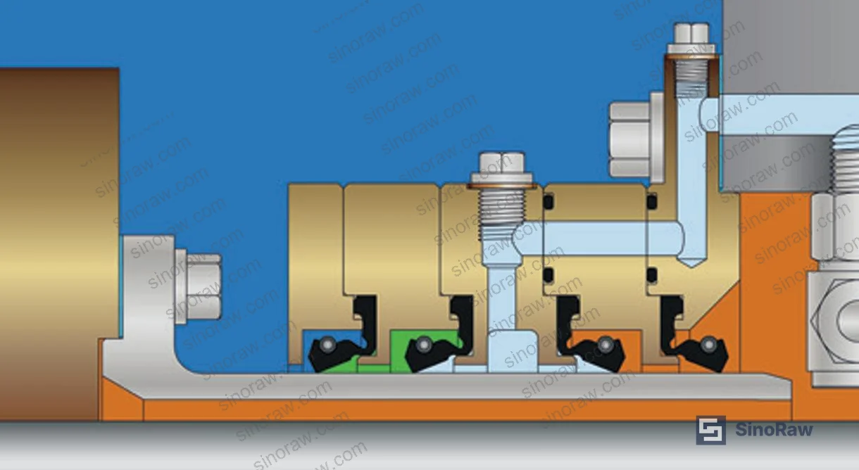
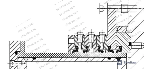
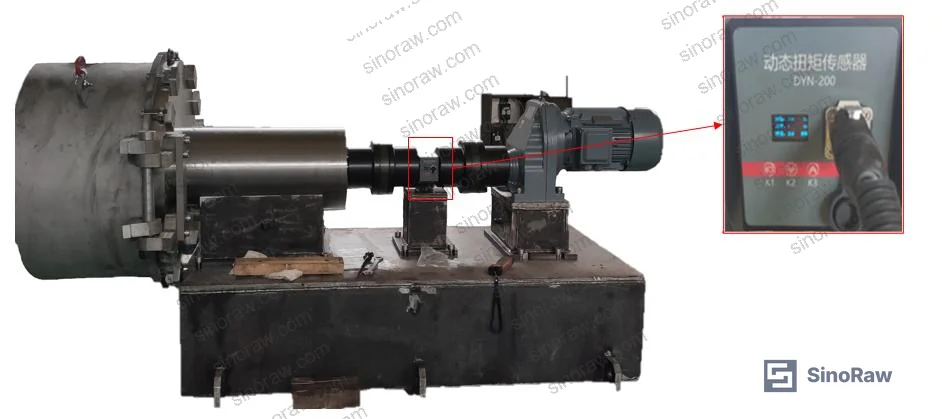
The evaluation summarized here was conducted by a specialist marine propulsion research institute using a full-scale, purpose-built test rig designed to reproduce combined polar operating conditions with programmable control over six independent parameters. The platform included a 5-lip seal assembly operating in a simulated seawater cavity, with real-time monitoring of friction torque, air consumption, leakage status, supply oil pressure/temperature, and shaft speed across all test modes. This is not a simplified bench test — the seal geometry, materials, and lubrication medium matched a deployed high ice-class pod propulsion system.
This type of rigorous, multi-parameter qualification data is exactly what procurement engineers should be demanding from Chinese suppliers before signing off on sealing system RFQs. At sinoraw.com, we work with verified manufacturers across marine sealing and related Pump & Valve Seals categories — but the specification discipline starts with understanding what the test data actually tells you.
For context on how sealing systems interact with broader fluid management design, see our Fluid Control documentation.
Rotating Seal Performance Under Variable Depth and Speed Conditions #
The most practically useful finding from variable-depth testing is this: seal opening pressure and water depth have an approximately linear relationship. At 300 rpm shaft speed across simulated depths of 4–24 m, opening pressure tracked the corresponding hydrostatic load consistently — and the dynamic opening pressures matched static test values closely, confirming that shaft rotation at this speed range does not meaningfully perturb the pressure balance.

What this linearity means for system design: you can use static pressure-depth calibration data to set minimum air cavity operating pressure at any design depth. The gravity oil tank level or compressed air supply parameters can be derived directly from this relationship. That is a significant simplification for field commissioning — provided your supplier can actually produce that calibration curve for their specific seal geometry.
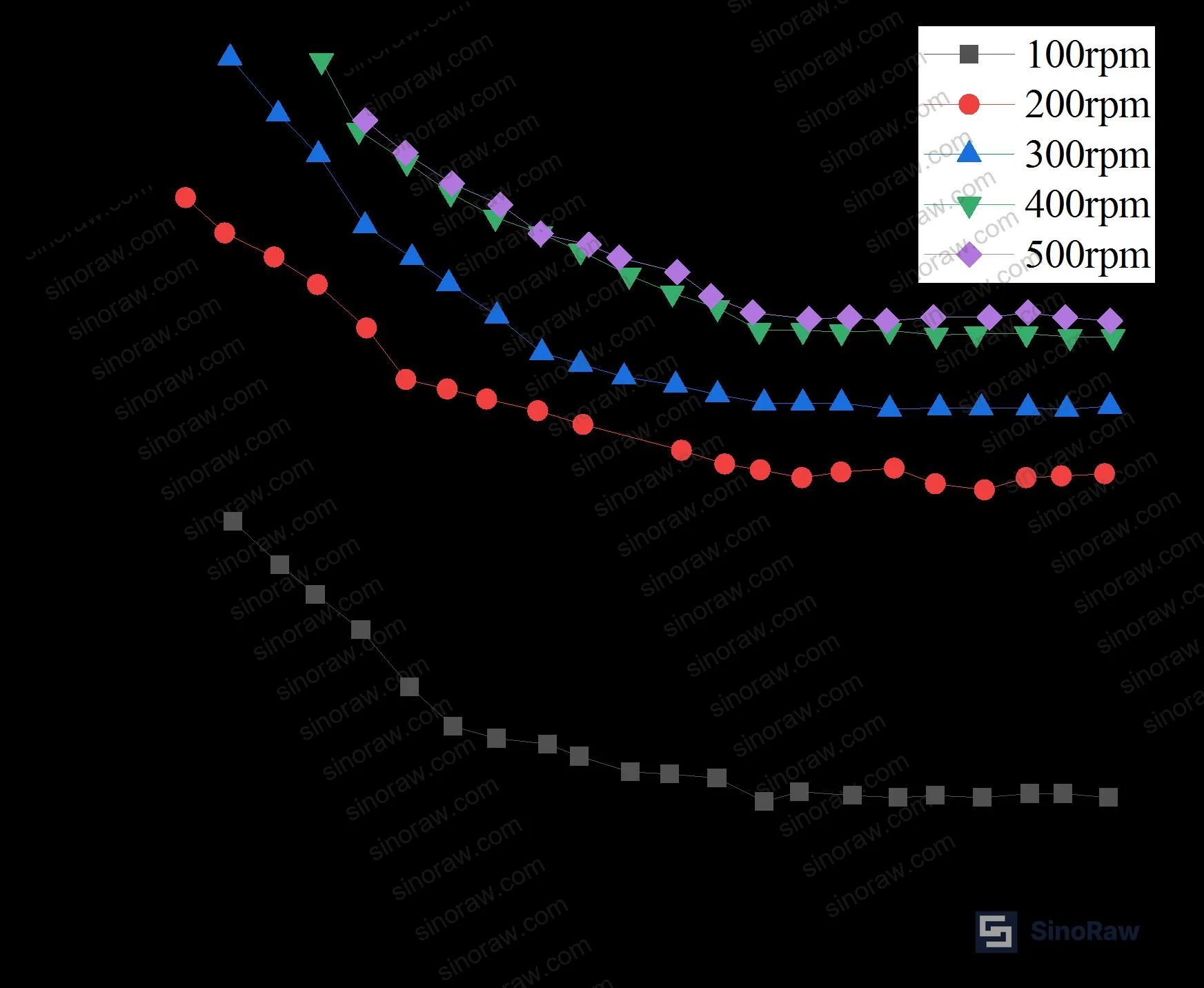
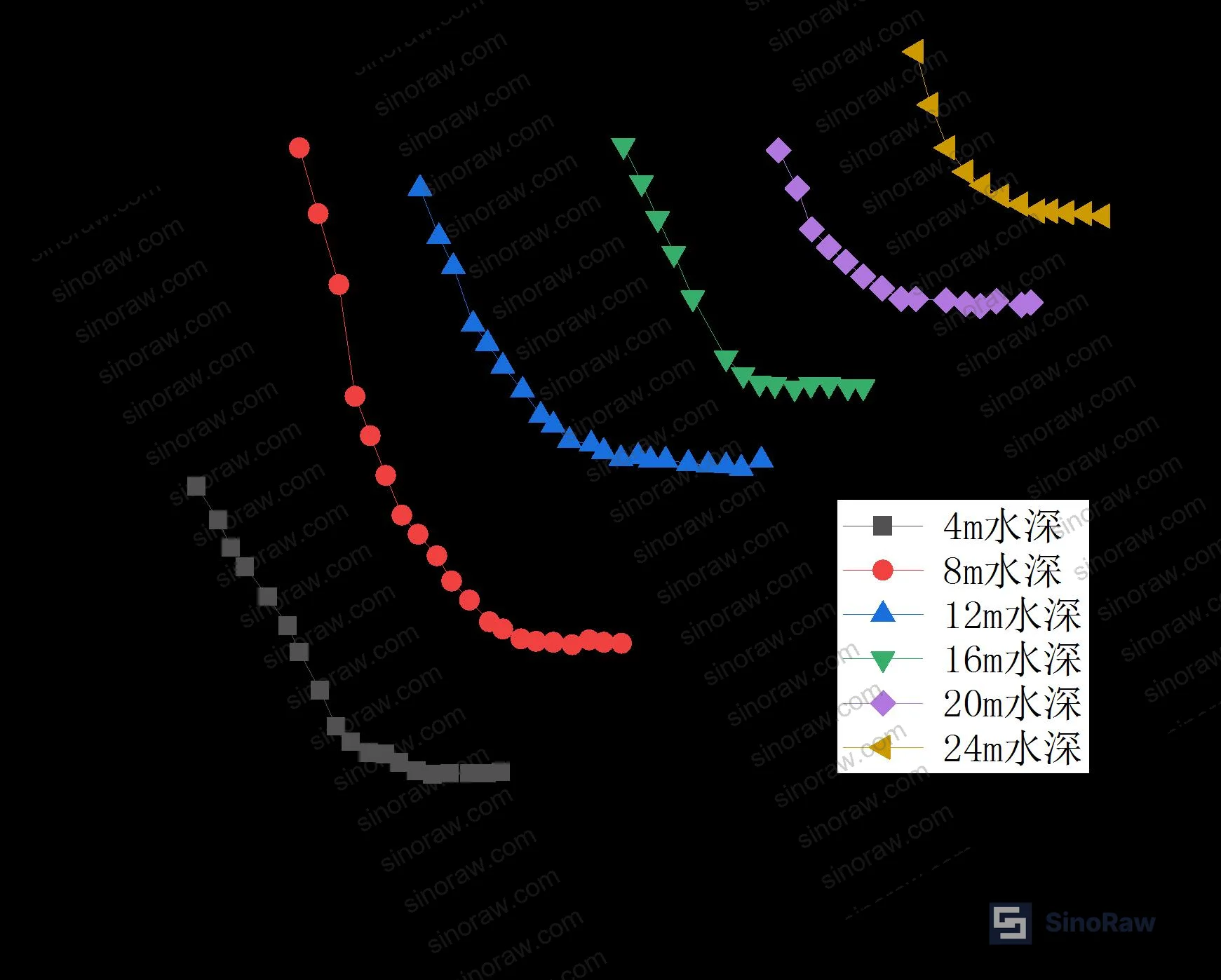
During variable-speed testing from 100 rpm to 500 rpm, friction torque consistently decreased as air cavity pressure increased, ultimately stabilizing at a constant value. The air cavity pressure at which torque first reached this plateau was measured at approximately 0.28 MPa — this is the functional seal opening pressure under dynamic conditions. At opening, air consumption jumped sharply from a baseline of 3–17 L/min to approximately 50 L/min, providing a clear and detectable threshold signal. Across all speed and depth combinations, continuous 2-hour operation produced zero oil or water leakage at the test drain port.
Variable-depth air consumption showed the same step-change pattern: baseline flow of 10–17 L/min rising to 40–50 L/min at opening, consistent across all tested depths. Buyers specifying compressed air supply systems for pod seal lubrication should treat 50 L/min as the peak instantaneous demand figure, with the 10–17 L/min range representing steady-state pre-opening consumption.
| Test Condition | Seal Opening Pressure | Air Consumption at Opening | Leakage Result |
|---|---|---|---|
| Variable speed (100–500 rpm), static depth | ~0.28 MPa | Jumps to ~50 L/min | Zero oil/water (2 h continuous) |
| Variable depth (4–24 m), 300 rpm | Tracks hydrostatic linearly | 40–50 L/min at opening | Zero oil/water (2 h continuous) |
| Static test (depth simulation only) | Linear with seawater pressure | — | Zero oil/water (2 h continuous) |
| Pressure fluctuation (±0.03 MPa, 300 rpm, 12 m depth) | Opening maintained within normal range | Cyclic variation, values within normal operating interval | Zero oil/water (2 h continuous) |
| Shaft eccentricity (0.05–0.20 mm, 300 rpm, 12 m depth) | Negligible change in opening pressure | Minor variation | Zero oil/water (2 h continuous) |
Honestly, most buyers over-specify rotational tolerance for these seals and under-specify the air supply system. The data is clear: shaft speed in the 100–500 rpm operating envelope has minimal effect on opening pressure. What will compromise your seal system is an undersized compressed air supply that cannot deliver the 50 L/min surge demand at opening, or a gravity oil tank sized for calm-water static pressure without accounting for depth variation.
Temperature and Eccentricity Effects on Polar Seal Friction and Stability #
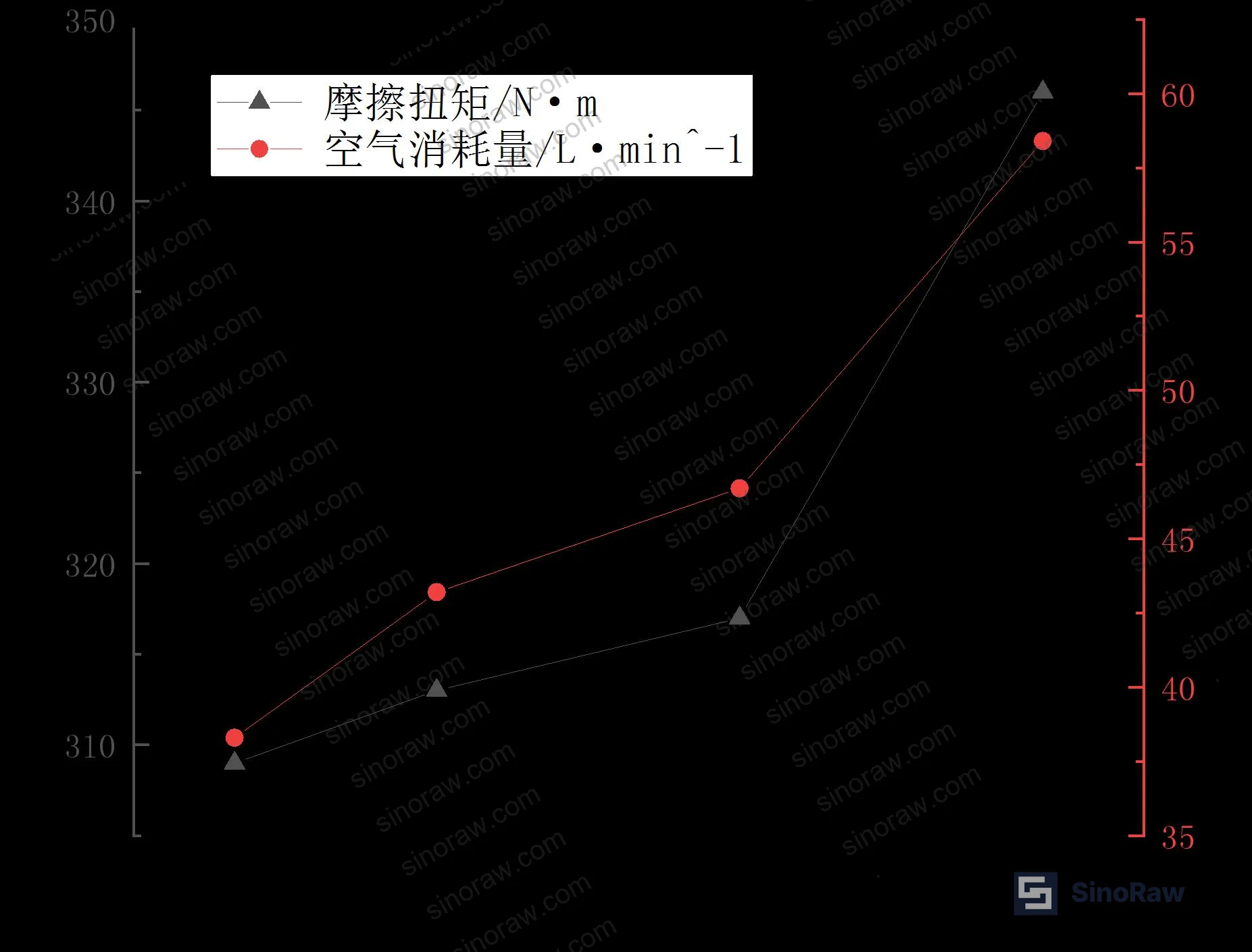
Temperature is the most operationally treacherous variable in this dataset. Under controlled conditions at 300 rpm, 12 m equivalent depth, and 0.25 MPa air cavity pressure, both friction torque and air consumption increased consistently as temperature rose from 0°C to 40°C. The relationship is monotonic: higher temperature softens the elastomeric lip material, reduces elastic modulus, and changes lubricating oil viscosity — all in directions that increase contact area and interfacial friction simultaneously.

The practical implication is counterintuitive to buyers accustomed to cold-environment engineering: in polar service, the concern is not just low-temperature brittleness — warm-up phases and machinery room heat transfer can push seal temperatures into ranges where friction torque and air consumption increase substantially. Any supplier who cannot quantify this relationship for their specific lip seal compound is not a qualified source for polar applications.
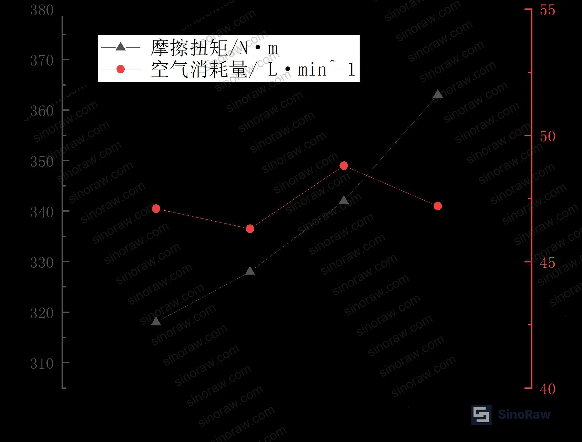
Shaft eccentricity test results were more nuanced. Friction torque increased with eccentricity at approximately 320 N·mm per mm of eccentricity — a near-linear relationship that reflects the enlarged contact surface between the lip and the wear sleeve as the shaft centerline shifts. This is mechanically straightforward.
What matters more: air consumption was largely insensitive to eccentricity across the 0.05–0.20 mm range tested. The seal continued to open normally at all eccentricity values. This is the result that tells you something important about robustness: if the seal can maintain normal opening behavior at 0.20 mm eccentricity, it has meaningful tolerance for assembly errors and operational shaft deflection without catastrophic loss of function.
In supplier qualification, we have seen friction torque drift outside the normal operating band on samples submitted for validation testing — not from eccentricity, but from inconsistent lip compound hardness between production batches. Three of six samples in one qualification run showed friction torque values at the upper bound of the normal range at temperatures above 25°C, pointing to compound variability as the failure risk, not the seal geometry itself. Batch-to-batch consistency in elastomeric material properties is not a paper specification question — it requires actual test data.
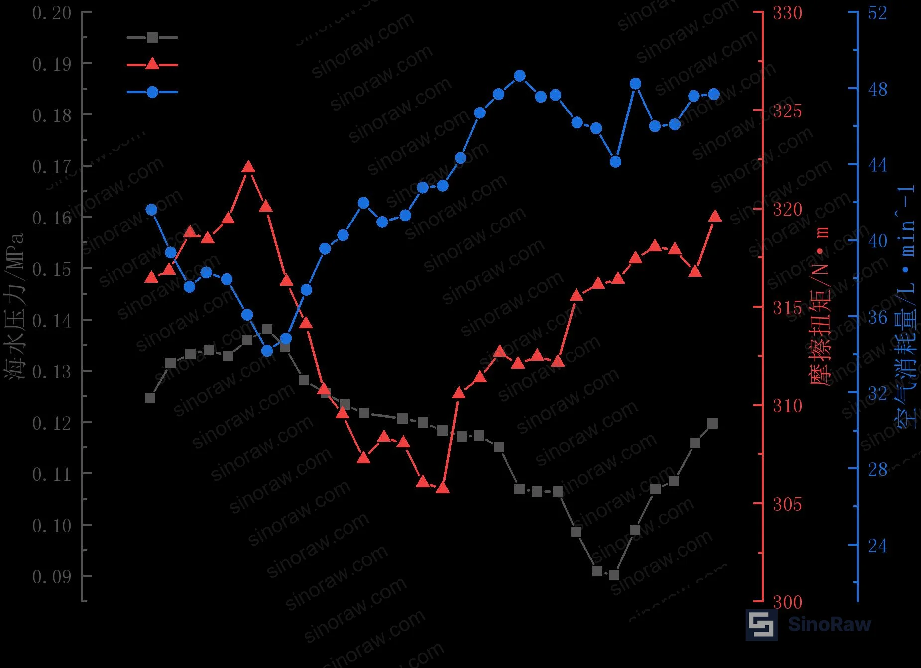
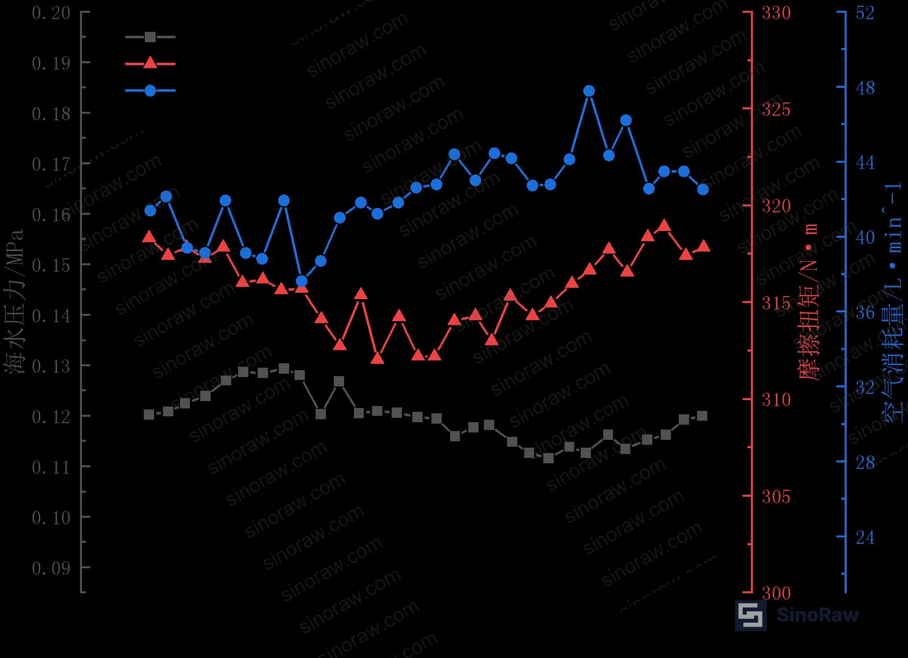
Pressure fluctuation testing used sinusoidal seawater pressure variations of ±0.01 MPa and ±0.03 MPa superimposed on the 12 m baseline depth pressure. Friction torque and air consumption both showed periodic variation tracking the pressure cycle, with torque exhibiting some phase lag — consistent with the finite response time of the elastomeric lip contact geometry. Importantly, all peak values remained within the normal operating band, and the seal maintained normal opening even at the maximum tested fluctuation of ±0.03 MPa (equivalent to a ±3 m depth oscillation). Pressure fluctuation tolerance is a relevant parameter for ice-breaking operations, where hull motion can create significant water column oscillations.
Most procurement teams don’t fully account for the coupled effect of high water depth combined with elevated temperature — this is an emerging area where seal material specifications need to address both simultaneously, not as independent worst-case conditions. When deep operation and warm machinery temperatures coincide, the seal operates at maximum external pressure while the lip compound is at its most compliant. Seal specifications that address only low-temperature brittleness as the polar performance criterion are missing half the operational envelope.
Compliance with ISO 9001:2015 Quality management systems at the manufacturing level is necessary but not sufficient for polar-grade sealing components — you need documented process control on elastomeric compound mixing and cure parameters, not just quality management certification. And because these sealing systems operate in direct contact with the marine environment, material compliance with REACH Regulation (EC) No 1907/2006 for any lubricating additives or elastomeric plasticizers is a non-negotiable baseline. Suppliers targeting European-flagged vessel applications should also be prepared to demonstrate RoHS Directive 2011/65/EU compliance for any electronic monitoring and control components in the lubrication system package.
Practical Guidance for Buyers #
If you are sourcing rotating shaft seal systems for ice-class pod propulsion, the critical specification hierarchy based on this test data is: (1) seawater pressure range maps directly to seal opening pressure requirement — calculate from maximum operating depth and add margin; (2) temperature range must cover the full operational thermal envelope, not just minimum ambient; (3) shaft eccentricity tolerance should be specified at the system level, with friction torque allowance calculated at approximately 320 N·mm per mm of eccentricity.
Do not accept seal opening pressure data measured only in static conditions. Require dynamic test data — the close match between static and dynamic opening pressures in this dataset is a characteristic of well-designed systems, not a universal given. A supplier who can only provide static test results has not validated their product for operational conditions.
Air supply system sizing is routinely underestimated. The jump from 3–17 L/min to approximately 50 L/min at seal opening is not a failure mode — it is normal operation. Specify your compressed air supply system for 50 L/min peak demand at the maximum operating depth pressure, then add system losses.
As a Guangzhou-based B2B sourcing specialist, sinoraw.com works directly with verified Chinese manufacturers of marine sealing components and lubrication system hardware — our technical team can cross-reference supplier qualification data against the performance benchmarks described here and help you shortlist candidates before issuing a formal RFQ.
Need help identifying qualified suppliers for polar-grade rotating shaft seals and lubrication systems? Talk to our sourcing team →
Supplier Qualification Questions #
- Can you provide dynamic seal opening pressure data measured across a depth range of 4–24 m equivalent water pressure, and confirm that dynamic values match static calibration values within what tolerance?
- What is your measured friction torque vs. temperature relationship for the lip seal compound at 300 rpm and 0.25 MPa air cavity pressure across the 0–40°C range, and what is the compound’s elastic modulus specification at 0°C versus 40°C?
- At the published seal opening pressure of approximately 0.28 MPa, what is the measured air consumption rate, and how does your design accommodate the step-change from baseline 3–17 L/min to peak 50 L/min without supply pressure collapse?
- Can you provide friction torque vs. shaft eccentricity data in the 0.05–0.20 mm range, and confirm the torque sensitivity is within 320 N·mm per mm of eccentricity for your specific seal geometry and wear sleeve material?
- Has the complete seal-lubrication system been validated for continuous 2-hour zero-leakage operation under simultaneous variable-depth and pressure fluctuation conditions — specifically ±0.03 MPa pressure variation superimposed on operating depth pressure — and can you supply the test records?
Sourcing Checklist #
- ☐ Supplier can provide dynamic seal opening pressure vs. water depth data (4–24 m range minimum) confirming linear pressure-depth relationship
- ☐ Friction torque and air consumption test data available for temperature range 0–40°C at specified operating speed and depth conditions
- ☐ Air supply system capacity documented at ≥50 L/min to accommodate seal opening demand surge
- ☐ Shaft eccentricity tolerance specified with corresponding friction torque data; torque sensitivity confirmed at ≤320 N·mm per mm eccentricity
- ☐ Continuous 2-hour zero-leakage test completed under all six standard condition categories: static, variable speed (100–500 rpm), variable depth, variable temperature, pressure fluctuation, and shaft eccentricity
- ☐ Lip seal elastomeric compound batch release specification includes hardness and elastic modulus testing, with documented batch-to-batch consistency controls
- ☐ Lubrication system components (oil pump, filter, heat exchanger, monitoring sensors) sourced and validated as integrated package, not individual components assembled from multiple unqualified suppliers
- ☐ REACH compliance documentation available for lubricating oil additives and elastomeric plasticizers used in seal compound
Key Specifications Table #
| Parameter | Recommended Value | Verification Method |
|---|---|---|
| Seal opening pressure at 12 m depth | ~0.28 MPa (dynamic, at 300 rpm) | Gradual air cavity pressure increase; opening confirmed by bubble formation in seawater cavity; torque plateau indicates opening threshold |
| Air consumption at seal opening | 40–50 L/min (peak demand) | Gas mass flow meter on air supply line; step-change from 10–17 L/min baseline confirms opening event |
| Shaft eccentricity friction torque sensitivity | ≤320 N·mm per mm eccentricity | Torque sensor measurement at 0.05–0.20 mm controlled eccentricity increments at 300 rpm, 0.25 MPa air cavity |
| Pressure fluctuation tolerance | Normal opening maintained at ±0.03 MPa superimposed variation | Sinusoidal seawater pressure variation test; all torque and air consumption peaks must remain within normal operating band |
| Continuous leakage-free operation | ≥2 hours with zero oil or water at drain port | Real-time leakage monitoring under each test condition category |
| Operating depth range (design validation) | 4–24 m (hydrostatic pressure equivalent) | Static and dynamic pressure-depth calibration; dynamic opening pressure to match static values within test measurement tolerance |
Can’t find a supplier meeting these specs? Submit your requirements and we’ll match you within 48 hours.
References #
Data source: Experimental Verification of Rotating Seal and Lubrication System Performance for High Ice-Class Podded Propulsion Main Shafts Under Simulated Polar Operating Conditions, B.-X. Zhang et al., Ocean Engineering, 2025
Frequently Asked Questions #
Why does seal opening pressure matter more than shaft speed when specifying ice-class rotating seals?
Test data across 100–500 rpm confirms that shaft speed in the typical pod propulsion operating range has minimal effect on opening pressure. Seal opening is controlled primarily by the balance between seawater hydrostatic pressure and air cavity pressure. Shaft speed affects friction torque magnitude and stability, but does not shift the pressure threshold at which the seal transitions from closed to open. Specifying shaft speed tolerance tighter than operationally necessary adds cost without improving sealing reliability.
What causes the sharp jump in air consumption when the seal opens?
When air cavity pressure reaches the threshold value (approximately 0.28 MPa under dynamic conditions at operating depths), the lip seal interface transitions from a closed contact state to an active flow state where compressed air bubbles through the seawater-side lip. This transition is the designed operating mode — the seal uses positive air pressure to prevent seawater ingress, and the air flow jump from 3–17 L/min to approximately 50 L/min is the signature of correct operation. Buyers should treat this as a diagnostic signal: an air consumption that does not show this step-change pattern may indicate a seal that is not opening properly, with implications for friction heat buildup.
How should temperature effects be handled in seal system design for vessels operating between cold Arctic water and warm machinery spaces?
Both friction torque and air consumption increase monotonically with temperature across the 0–40°C tested range. This is driven by temperature-dependent changes in lip compound elastic modulus and lubricating oil viscosity. For system design, this means the seal friction load and air demand at the warm end of the operating range should be treated as the sizing condition for the lubrication and air supply systems — not the cold-water minimum condition.
Is 0.20 mm shaft eccentricity within acceptable limits for this type of seal?
The test data shows that air consumption — and therefore seal opening function — is largely insensitive to eccentricity across the 0.05–0.20 mm range. Friction torque does increase at approximately 320 N·mm per mm of eccentricity, which is mechanically predictable and manageable within normal drive system margins. The key finding is that eccentricity in this range does not prevent normal seal opening, which means the system has inherent robustness against typical assembly tolerances and operational shaft deflection. Eccentricity beyond 0.20 mm was not tested and should be treated as outside the validated envelope.
What is the significance of matching the test rig seal geometry and materials to an actual deployed system?
It means the test data can be directly applied to engineering design without dimensional scaling corrections. Seal opening pressure vs. depth relationships, air consumption rates, and friction torque values from the test platform translate directly to the deployed system design parameters — specifically for setting gravity oil tank levels, compressed air supply sizing, and shaft alignment tolerances. This direct applicability is what separates useful qualification data from academic bench-scale results that require extrapolation before they can inform a procurement specification.
Published by sinoraw.com Technical Team | Request a sourcing quote


