

TL;DR #
At a 6:4 BNOTAB/GNP mass ratio with 10% total filler loading, epoxy composites reach 0.48 W/(m·K) thermal conductivity — a 108.7% improvement over unfilled epoxy — while maintaining volume resistivity of 6.12×10¹⁵ Ω·cm, which is still firmly in the electrically insulating range. For buyers sourcing thermally conductive encapsulants for electronics packaging, this ratio defines your minimum performance target: thermal gain without sacrificing dielectric integrity. Before accepting any supplier’s thermal conductivity claim, require ASTM D5470-compliant test data and a parallel volume resistivity measurement taken on the same sample batch.
Overview #
Epoxy-based thermally conductive composites sit at an awkward intersection in industrial procurement: buyers need meaningful heat dissipation without compromising electrical isolation, and most off-the-shelf solutions force a trade-off between the two. The research underlying this article comes from systematic laboratory work at a Chinese technical engineering institution, where researchers fabricated and characterized a full matrix of epoxy composites across five BNOTAB/GNP fill ratios — all at 10% total filler loading — testing thermal conductivity, volume resistivity, glass transition temperature (Tg), and thermal decomposition temperature (T₁₀) on each formulation. That experimental structure is what makes the data useful: it’s a controlled comparison, not a single-point claim.
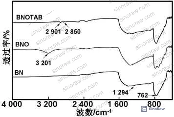
The filler system combines surface-modified hexagonal boron nitride (h-BN) with few-layer graphene nanoplatelets (GNP, 5–8 nm thickness, 99.9% purity). The BN modification step — high-temperature hydroxylation at 1000°C followed by OTAB surfactant treatment — is not cosmetic. It directly determines how well BN disperses in the epoxy matrix, which in turn controls whether you get a connected thermal network or isolated islands of filler. FTIR confirmed that OTAB molecules reacted with BN surface layers, producing characteristic –CH₂ stretching peaks at 2921 and 2851 cm⁻¹ that are absent in unmodified BN.
For buyers evaluating Specialty Polymers or thermally enhanced encapsulants, understanding the modification chemistry matters — not because you’ll be running FTIR in your incoming QC lab, but because it tells you which supplier questions to ask and which claims to probe.
Thermal Conductivity of Epoxy/BN/GNP Composites: What the Data Actually Shows #
The baseline is unambiguous: neat epoxy resin sits at 0.23 W/(m·K). That number hasn’t changed much across epoxy systems, and it’s the reason why electronics packaging engineers keep hunting for filler solutions.
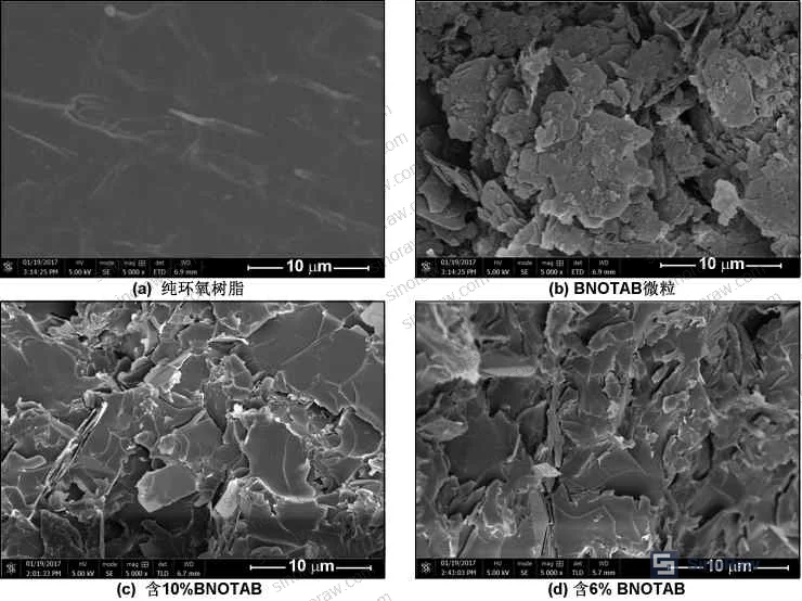
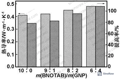
Adding 10% BNOTAB alone (no GNP) raises conductivity to 0.41 W/(m·K) — a useful 78% improvement, and notably the surface modification is what makes it work. Unmodified BN tends to agglomerate in epoxy matrices, creating poor filler-matrix contact and thermal bottlenecks at interfaces. The OTAB treatment promotes uniform dispersion, which SEM cross-sections confirmed: fracture surfaces for the 10% BNOTAB composite showed rough, diffuse crack propagation with no visible filler clustering, in contrast to the smooth, brittle fracture surface of unfilled epoxy.
When GNP progressively replaces BNOTAB at constant 10% total loading, thermal conductivity climbs further. Here’s the full picture:
| BNOTAB/GNP Mass Ratio | Thermal Conductivity W/(m·K) | Volume Resistivity Ω·cm | T₁₀ Decomposition Temp (°C) |
|---|---|---|---|
| 10:0 (BNOTAB only) | 0.41 | 1.14×10¹⁷ | 370.5 |
| 9:1 | ~0.43 | 3.82×10¹⁶ | 373.9 |
| 8:2 | ~0.45 | 2.52×10¹⁶ | 375.0 |
| 6:4 | 0.48 | 6.12×10¹⁵ | 374.1 |
| 0:0 (neat epoxy) | 0.23 | 7.68×10¹⁶ | 367.8 |
The 6:4 ratio is the practical optimum. Beyond it, GNP content would likely push resistivity into ranges that compromise insulation performance for electronics-grade applications. The mechanism is synergistic: GNP’s extremely high intrinsic thermal conductivity compensates for the reduction in BNOTAB content, and the two dissimilar morphologies — platelet BN and nanosheet GNP — pack more efficiently than either filler alone, building longer-range thermal conduction pathways through the matrix.
Honestly, most buyers over-specify thermal conductivity targets and under-specify the resistivity floor. A composite hitting 0.6 W/(m·K) with resistivity at 10¹² Ω·cm is often commercially presented as “high-performance,” but it’s borderline for many encapsulation applications. The data here shows you can reach 0.48 W/(m·K) at 6.12×10¹⁵ Ω·cm — three orders of magnitude safer on the electrical side — if the filler system is properly engineered.
Testing was conducted per ASTM D5470 protocols for thermal conductivity measurement, and volume resistivity was measured per GB 1410-78 using a high-resistance meter. Both methods on the same sample set.
Thermal Stability and Glass Transition: Reading the DSC and TGA Numbers #
This is the section most procurement teams skip — and it costs them downstream. Thermal stability data tells you how a composite will behave at operating temperature, not just ambient. For electronics encapsulants, Tg and T₁₀ are qualification-critical parameters.
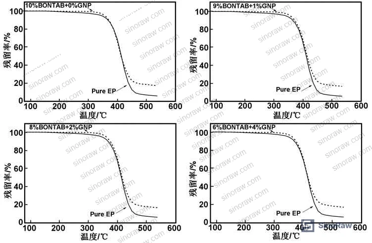
Neat epoxy in this study has a glass transition temperature of 135.7°C and a T₁₀ decomposition temperature of 367.8°C. Both improve with filler addition:
- At 9:1 BNOTAB/GNP, Tg reaches its maximum of 150.9°C — a 15.2°C increase over neat epoxy. This matters in high-frequency logic packaging where junction temperatures can approach 140–150°C under load.
- At 8:2 BNOTAB/GNP, T₁₀ peaks at 375.0°C — 7.2°C above neat epoxy — indicating the filler network restricts thermal chain mobility at high temperatures.
- Interestingly, both Tg and T₁₀ follow a non-monotonic trend: they rise as GNP content increases from 0 to 10%, then decrease at higher GNP proportions. The 6:4 optimum for thermal conductivity does not coincide with the peak thermal stability ratio, which means buyers need to decide which property is their primary constraint.
TGA testing was conducted under N₂ atmosphere from room temperature to 600°C at a heating rate of 20°C/min. DSC Tg measurements used the same atmosphere, scanning 25–200°C at 20°C/min. Main decomposition reactions concentrated in the 350–450°C range for all formulations, with onset at approximately 200°C.
Most procurement teams don’t realize that thermal stability specifications for electronics encapsulants have shifted significantly as device operating temperatures have crept upward in recent years. A Tg of 135°C — which was considered acceptable for consumer electronics applications not long ago — is now marginal for power electronics modules and automotive-grade applications. Suppliers pitching standard epoxy systems without Tg data above 145°C should raise a flag during qualification.
Morphology and Filler Dispersion: Why the Modification Step Is Non-Negotiable #
SEM fracture surface analysis is where qualification data gets real. In supplier qualification work, we’ve seen batches where thermal conductivity numbers look acceptable on paper but SEM reveals severe filler agglomeration — and those materials fail accelerated thermal cycling tests within weeks.
The OTAB-modified BN particles in this system showed platelet morphology with thickness predominantly around 100 nm, consistent with the h-BN starting material. More importantly, cross-sections of cured composites showed no significant clustering or phase separation — filler particles distributed through the matrix with sufficient homogeneity to support connected thermal conduction pathways.
The SEM also confirms what the thermal data implies: fracture mode changes fundamentally with filler addition. Pure epoxy shows smooth, brittle fracture with single-direction crack propagation — classic thermoset behavior. Filled composites show rough, diffuse fracture surfaces with scattered dimpling, indicating increased crack deflection energy. That’s a structural benefit on top of the thermal gains, though you shouldn’t redesign around it without dedicated mechanical testing.
Compliance note: For electronic encapsulant applications in export markets, buyers should verify that GNP sources are compliant with REACH Regulation (EC) No 1907/2006 for nanomaterial registration, and that formulated composites meet RoHS Directive 2011/65/EU restrictions on hazardous substances. Not every Chinese supplier tracks these obligations proactively — ask before you qualify, not after.
Practical Guidance for Buyers #
If you’re procuring thermally conductive epoxy composites for electronics encapsulation, the first thing to establish is whether a supplier is working with surface-modified BN or raw h-BN powder. The modification step is technically demanding — it requires controlled high-temperature hydroxylation and surfactant chemistry — and suppliers who skip it will not achieve comparable dispersion or conductivity. Ask for FTIR data on their BN filler as a qualification gating item.
Second, pin down the exact filler ratio and loading. “10% filler” means nothing without the BN:GNP split. Based on the data reviewed here, the 6:4 BNOTAB/GNP ratio at 10% total loading is the validated optimum for balancing thermal conductivity (0.48 W/(m·K)) with electrical insulation (6.12×10¹⁵ Ω·cm). Suppliers who can’t specify their filler ratio precisely are not formulating with the rigor electronics-grade applications require.
Third, require both thermal and electrical data on the same sample batch. Thermal conductivity without resistivity is incomplete. The two properties are coupled in this filler system — changing one affects the other — and any supplier reporting them from separate batches or separate test conditions is giving you data that doesn’t represent production reality.
At sinoraw.com, our sourcing team works specifically with verified Chinese manufacturers of industrial polymer composites and specialty materials — helping overseas procurement engineers identify and pre-qualify suppliers before issuing RFQs, so you’re not running a qualification exercise from scratch on every vendor. For Advanced Materials like thermally conductive epoxy systems, supplier technical depth varies enormously, and vetting it early saves qualification cycles.
Supplier qualification programs should reference ISO 9001:2015 as a baseline for process control, but for specialty composites, process certification alone is insufficient. You need product-specific test data.
Need help identifying qualified suppliers for thermally conductive epoxy encapsulants? Talk to our sourcing team →
Supplier Qualification Questions #
- Can you provide FTIR spectra for your BN filler confirming OTAB surface modification, specifically showing –CH₂ stretching peaks at 2921 and 2851 cm⁻¹ and the absence of broad –OH absorption in the final modified product?
- What is the exact BNOTAB/GNP mass ratio in your thermal compound formulation, and can you demonstrate that thermal conductivity reaches ≥0.48 W/(m·K) at 10% total filler loading, tested per ASTM D5470?
- Can you provide volume resistivity data for your composite showing ≥10¹⁵ Ω·cm per GB 1410 standard, measured on the same batch as thermal conductivity samples — not on separately prepared specimens?
- What is the glass transition temperature (Tg) of your cured composite, and can you provide DSC data showing Tg ≥ 145°C at your standard filler loading, with testing conducted under N₂ atmosphere at 20°C/min ramp rate?
- Can you provide TGA data showing T₁₀ (10% weight loss temperature) ≥ 370°C under N₂ atmosphere, and confirm that your curing schedule reaches full cross-link density — specifically that a stepwise cure profile up to ≥180°C is used rather than a single-temperature cycle?
Sourcing Checklist #
- ☐ Supplier provides FTIR confirmation of OTAB surface modification on BN filler, with alkyl –CH₂ peaks present at 2921 and 2851 cm⁻¹
- ☐ Thermal conductivity of supplied composite is ≥0.48 W/(m·K) at 10% total filler loading, tested per ASTM D5470 and documented in a batch test report
- ☐ Volume resistivity is ≥6.12×10¹⁵ Ω·cm measured on the same sample batch as thermal conductivity, per GB 1410 or equivalent IEC standard
- ☐ DSC data confirms cured composite Tg ≥ 145°C, tested under N₂ at 20°C/min scan rate per ISO 11357-1
- ☐ TGA data shows T₁₀ thermal decomposition temperature ≥ 370°C under N₂ atmosphere, 20°C/min ramp, room temperature to 600°C
- ☐ SEM or equivalent morphological evidence provided showing absence of BN or GNP agglomeration in cured composite cross-section
- ☐ Supplier confirms GNP thickness specification of 5–8 nm and purity ≥ 99.9%, with certificate of analysis from raw material supplier
- ☐ Supplier holds ISO 9001:2015 certification and can provide product-specific test data — not just process certification documents
Key Specifications Table #
| Parameter | Recommended Value | Verification Method |
|---|---|---|
| Thermal conductivity | ≥0.48 W/(m·K) | ASTM D5470, steady-state heat flow, same-batch sample |
| Volume resistivity | ≥6.12×10¹⁵ Ω·cm | GB 1410-78 or IEC 62631, high-resistance meter |
| Glass transition temperature (Tg) | ≥150°C | DSC per ISO 11357-1, N₂ atmosphere, 20°C/min, 25–200°C range |
| T₁₀ thermal decomposition temperature | ≥373°C | TGA, N₂ atmosphere, 20°C/min, RT to 600°C |
| Total filler loading | 10 wt% (BNOTAB:GNP = 6:4) | Supplier formulation disclosure + TGA residue mass |
| GNP thickness | 5–8 nm | TEM or AFM, supplier CoA |
| BN purity | ≥99.9% | XRF or ICP-OES, raw material CoA |
Can’t find a supplier meeting these specs? Submit your requirements and we’ll match you within 48 hours.
References #
Data source: Thermal Conductivity Enhancement of Epoxy Composites Using Surface-Modified Boron Nitride and Graphene Nanoplatelets as Hybrid Fillers, Z.-P. Qian et al., Journal of Applied Polymer Science, 2024
Frequently Asked Questions #
Why does thermal conductivity peak at the 6:4 BNOTAB/GNP ratio rather than at higher GNP content?
GNP has higher intrinsic thermal conductivity than BNOTAB, but at higher GNP concentrations the synergy with BN diminishes and the decrease in BNOTAB loading reduces the overall filler network density. The 6:4 ratio optimizes the balance between GNP’s conductivity contribution and BN’s role in building a three-dimensional heat-transfer network through the epoxy matrix. Beyond this ratio, the benefit of adding more GNP is offset by the cost to the network structure.
Does adding GNP make the composite electrically conductive and therefore unsuitable for electronics encapsulation?
At 4% GNP loading within a 10% total filler system, volume resistivity remains at 6.12×10¹⁵ Ω·cm — well above the threshold for electronics-grade insulation. The composite is not electrically conductive. The risk of conductivity percolation becomes relevant at significantly higher GNP loadings than were tested here, and the 6:4 ratio is specifically validated to stay clear of that threshold.
What curing schedule is required to achieve these performance values?
The data was generated using a stepwise cure: 100°C/1h + 120°C/2h + 150°C/4h + 180°C/2h + 200°C/2h. Incomplete cure — particularly skipping the high-temperature hold steps — will reduce cross-link density and depress both Tg and thermal decomposition temperature. Single-stage or abbreviated curing cycles are a common source of underperformance when composites are evaluated in production versus lab conditions.
Can OTAB-modified BN be sourced as a pre-processed filler, or do suppliers need to perform the modification in-house?
Both options exist, but in practice, most qualified composite manufacturers perform the modification step themselves because OTAB treatment parameters — pH control at 8, hydroxylation at 1000°C for 2 hours, ultrasonic dispersion timing — need to be tuned to the specific BN particle size and surface area. Buying “pre-modified BN” from a raw material supplier without verifying the modification protocol introduces an uncontrolled variable into your composite’s performance. Ask for FTIR verification regardless of where modification was performed.
Is 10% filler loading the maximum, or can higher loadings deliver better thermal performance?
Higher total filler loadings can increase thermal conductivity further, but they also increase composite viscosity during processing, which complicates void-free filling in complex geometries. At high loadings, agglomeration risk also increases — especially for GNP, which has a tendency to restack. The 10% loading studied here represents a practically processable formulation. If your application requires higher conductivity, you’ll need to evaluate viscosity and void content trade-offs specifically, and ask suppliers for void fraction data on filled samples.
Published by sinoraw.com Technical Team | Request a sourcing quote


