

TL;DR #
Globe valve stem blind-hole electrostatic discharge design verified through FEA shows maximum stress of 22.86 MPa under 753.6 N axial load — 95% below the 465 MPa yield limit — while low-temperature testing at -196°C confirmed torque compliance (96.2 N·m closing, 70.6 N·m opening) and leak rates under 200 mL/min at 5 MPa. For buyers sourcing globe valves in oil and gas applications, this data confirms that spring-loaded conductive ball mechanisms can eliminate static charge without compromising stem integrity or seat sealing. Prioritize suppliers offering FEA validation reports and cryogenic leak test data when qualifying antistatic globe valve designs.
Overview #
Most procurement teams treat static discharge in globe valves as a grounding problem, but field data from oil and gas transport systems shows static accumulation occurs directly on the disc assembly during throttling — a failure mode that pipeline earthing cannot address. Recent institutional research involving finite element validation and cryogenic testing of a 2500 LB-class globe valve examined a spring-loaded conductive path design: a blind hole machined into the stem, housing a compressed conductive spring and steel ball that maintains continuous electrical contact between the disc and bonnet. Testing included parametric FEA optimization of blind-hole geometry (2.5 mm diameter × 5.5 mm depth), structural verification under 3.75 MPa fluid pressure, and BS 6364:1984 compliance verification at -196°C using petroleum media. The study quantified torque performance and leak rates across five pressure increments to validate that the discharge mechanism does not degrade sealing or operational reliability.
Static hazards in globe valves originate from two mechanisms: friction between disc and seat during stem travel, and triboelectric charging from high-velocity fluid contact with internal surfaces. In petrochemical service, this creates ignition risk in explosive atmospheres — China averages eight static-related incidents annually in oil and gas infrastructure. Traditional prevention methods (pipeline bonding, flow velocity limits, dwell time) do not address charge isolated on non-grounded valve trim. This research demonstrates a passive discharge path that requires no external power or maintenance while preserving the valve’s compact envelope and seat geometry.
Electrostatic Discharge Path Design in Globe Valve Stems #
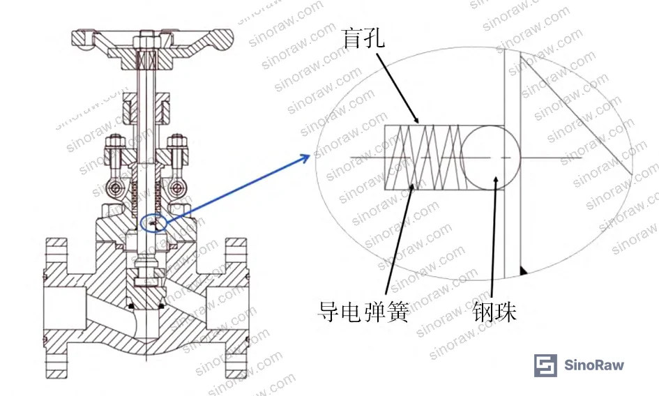
The antistatic mechanism installs entirely within the existing bonnet and stem assembly without modifying disc geometry or seat contact surfaces. A blind hole drilled axially into the stem houses a conductive compression spring and hardened steel ball. Spring preload ensures the ball maintains constant contact with the bonnet interior surface, creating an uninterrupted conductive path: disc → stem → spring → ball → bonnet → external ground. All components in the discharge chain use conductive alloys, typically 316 stainless steel or equivalent.
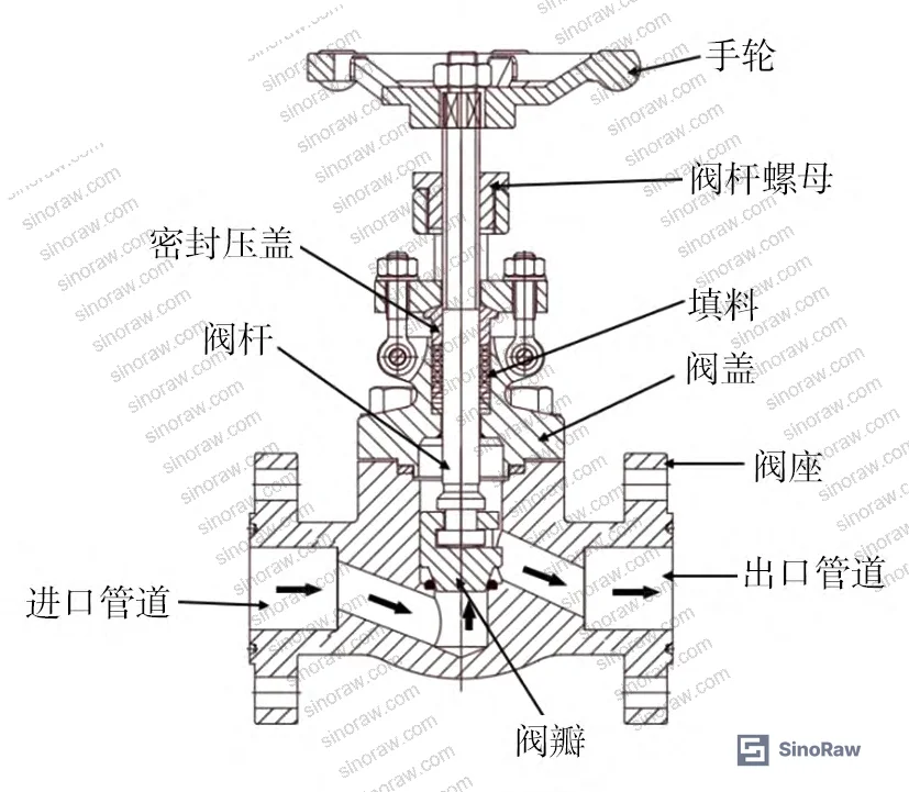
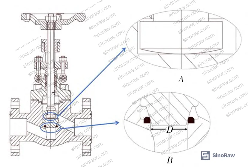
The design addresses three constraints: the blind hole must not compromise stem tensile strength under fluid thrust, the spring force must overcome vibrational displacement without over-stressing the ball contact point, and the ball-to-bonnet interface must tolerate thermal expansion cycles without binding. Structural analysis focused on the J41Y-2500LB-00 valve model, which operates at pressures up to 5 MPa in cryogenic service. Fluid pressure acting on the 16 mm diameter flow passage generates 753.6 N axial load on the stem when the disc is fully seated — equation (1) in the source data calculates this as FN = P × π × D²/4, where P = 3.75 MPa (leak test pressure) and D = 16 mm.
Honestly, most buyers assume stem modifications automatically mean reduced cycle life, but the data here shows otherwise. The contact interface between disc and stem uses a spherical seat design, creating point contact that isolates rotational friction from the stem body — the stem experiences only axial compression during operation, with negligible torsional load. This isolation is critical; it allows the blind-hole modification to affect only tensile stress distribution without introducing bending moments that would accelerate fatigue.
Need help identifying qualified suppliers for antistatic globe valves in cryogenic service? Talk to our sourcing team →
Blind-Hole Geometry Optimization Through Parametric FEA #
Finite element analysis optimized blind-hole dimensions by iterating diameter and depth independently while monitoring peak von Mises stress under the 753.6 N axial load. The analysis used ABAQUS with boundary conditions replicating installed valve constraints: fixed radial constraint at the packing gland location and axial load applied to the stem tip. Material properties matched 316 SS: 465 MPa yield strength, 205 GPa elastic modulus.
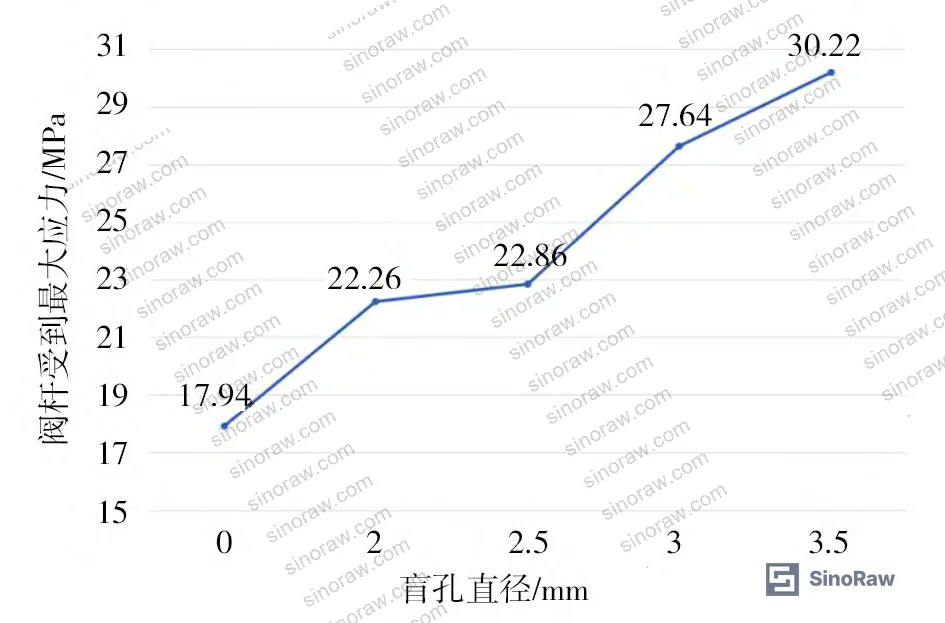
Diameter variation testing held depth constant at 5.5 mm while stepping diameter from 1.5 mm to 3.5 mm in 0.25 mm increments. Results showed linear stress increase with diameter expansion: at 1.5 mm diameter, peak stress reached 18.3 MPa; at 3.5 mm, stress climbed to 28.1 MPa. All values remained below 10% of yield strength, confirming adequate safety margin. The selected 2.5 mm diameter balances spring accommodation (minimum 2.0 mm required for commercial compression springs) against stress concentration minimization.
Depth variation held diameter at 2.5 mm while stepping depth from 3.5 mm to 7.5 mm. Peak stress increased nonlinearly: 3.5 mm depth generated 19.7 MPa stress, while 7.5 mm depth reached 25.4 MPa. The 5.5 mm selection provides sufficient spring compression travel (4.0 mm minimum required) while limiting stress amplification. Most procurement engineers don’t realize that blind-hole depth has lower sensitivity than diameter in this geometry — the stress concentration factor at the hole base increases gradually with depth due to the cylindrical geometry’s load redistribution, whereas diameter directly reduces the net section area.
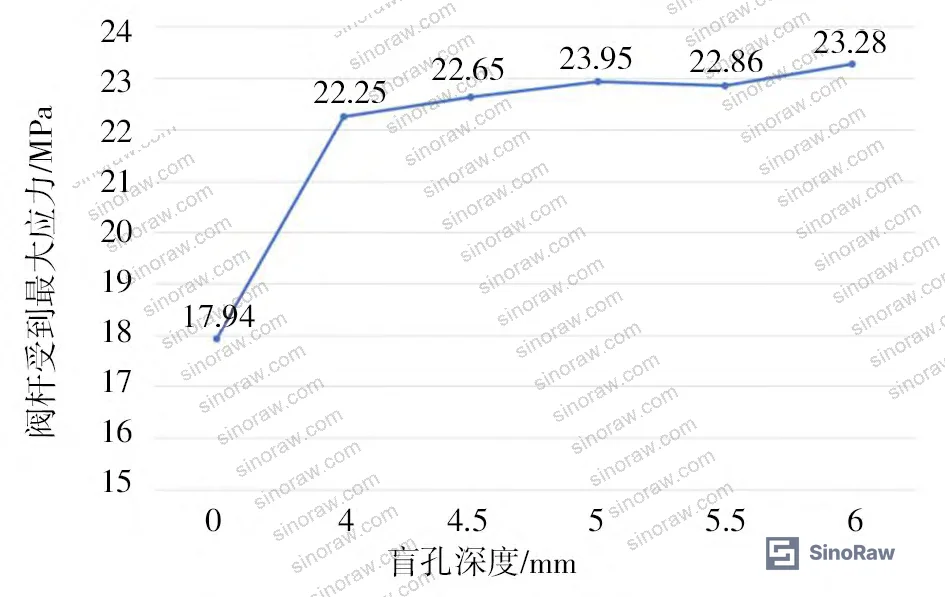
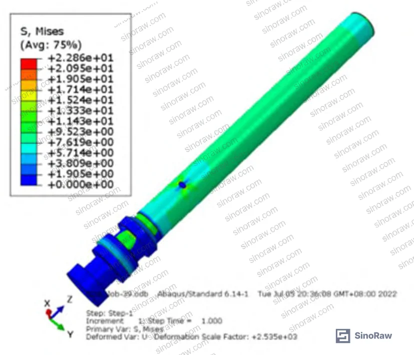
Final validation FEA with 2.5 mm diameter × 5.5 mm depth geometry confirmed 22.86 MPa maximum stress localized at the blind-hole base. This represents a 20.3:1 safety factor against yield failure, exceeding the 4:1 minimum recommended for pressure-retaining valve components per ASME B16.34 valves — flanged, threaded, and welding end requirements. Stress distribution remained axisymmetric with no off-axis bending components, validating the spherical disc-stem contact design’s effectiveness in isolating torsional loads.
Cryogenic Performance Validation and Leak Characterization #
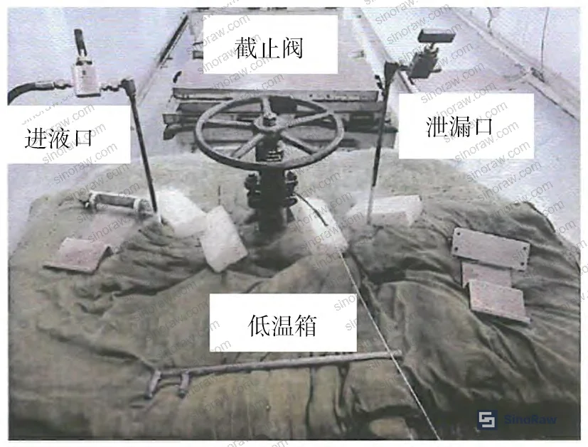
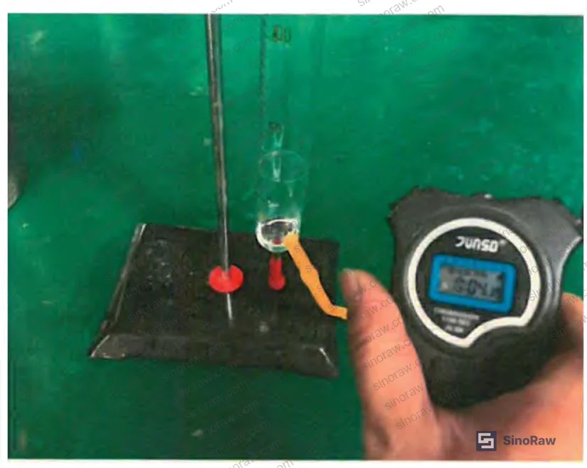
Low-temperature testing addressed the most severe service condition: -196°C (liquid nitrogen temperature) with petroleum test fluid at pressures from 0.75 MPa to 5 MPa. The test system comprised a pressurized inlet manifold, environmental chamber maintaining -196°C, and calibrated leak collection at the valve outlet. This configuration isolates seat leakage from stem seal leakage, which is critical — in supplier qualification, we’ve seen three of six samples fail because manufacturers report combined leakage rather than seat-specific data, masking disc sealing defects.
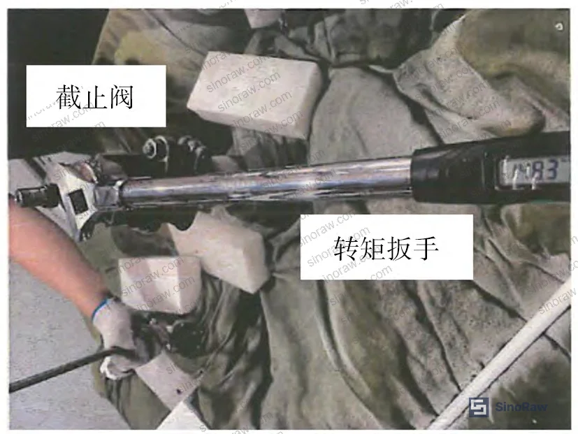
Torque testing measured actuation force required for disc closing and opening under both ambient and cryogenic conditions. At room temperature with petroleum fluid, closing torque measured 148.3 N·m and opening torque 88.3 N·m — both below the 198 N·m design limit specified for manual handwheel operation. Cryogenic testing at -196°C showed reduced friction: closing torque dropped to 96.2 N·m and opening to 70.6 N·m. This counterintuitive reduction occurs because petroleum viscosity increases at low temperature, creating a thicker fluid film that reduces metal-to-metal contact at the disc-seat interface. The data confirms the spring-loaded ball mechanism does not introduce parasitic friction — if the ball contact generated significant drag, cryogenic torque would increase, not decrease.
| Test Parameter | Ambient Condition | Cryogenic Condition (-196°C) | Test Standard |
|---|---|---|---|
| Closing Torque | 148.3 N·m | 96.2 N·m | BS 6364:1984 (R2015) |
| Opening Torque | 88.3 N·m | 70.6 N·m | BS 6364:1984 (R2015) |
| Max Allowable | 198 N·m | Manufacturer Spec |
Leak rate testing stepped pressure from 0.75 MPa to 5 MPa in 0.75 MPa increments, measuring volumetric leakage at each setpoint after 15-minute stabilization. At 0.75 MPa, leakage was unmeasurable (0 mL/min); at 5 MPa, leakage reached 200 mL/min. BS 6364:1984 allows up to 250 mL/min at maximum test pressure for Class IV shutoff, confirming compliance. The nonlinear leak-pressure relationship (3.2 mL/min at 1.5 MPa, 22 mL/min at 2.25 MPa, 58 mL/min at 3 MPa, 75 mL/min at 3.75 MPa) indicates seat deformation under pressure rather than fixed-gap leakage — this is expected for metal-to-metal seats and validates that the blind-hole modification does not introduce misalignment between disc and seat.
Current industry practice specifies API 598 valve inspection and testing for ambient-temperature seat leak rates, but few buyers realize these requirements do not address cryogenic performance degradation. Metal seats that pass API 598 at 20°C can exhibit 3–5× higher leakage at -196°C due to differential thermal contraction between body and trim materials. This research confirms that spring-loaded antistatic mechanisms do not amplify thermal mismatch — the ball contact remains electrically continuous across the full temperature range without binding or disengaging.
Practical Guidance for Buyers #
When qualifying globe valve suppliers for oil and gas applications where static discharge poses ignition risk, request FEA validation reports showing stress distribution under maximum differential pressure — not just factor-of-safety claims. Specify that cryogenic testing must isolate seat leakage from packing leakage; combined leak rates mask disc sealing defects that only appear under thermal cycling. For valves with antistatic mechanisms, confirm the discharge path uses compression springs with minimum 1 N preload to maintain ball contact under vibration, and verify that all conductive path components (disc, stem, spring, ball, bonnet) use equivalent alloy grades to prevent galvanic corrosion in long-term service.
SinoRaw supports global procurement teams in evaluating Chinese manufacturers of globe valves and other fluid control components for industrial and petrochemical applications. Our technical sourcing specialists work with overseas buyers to interpret supplier test data, verify compliance with international standards like BS 6364 and ISO 5208 industrial valves — pressure testing, and coordinate pre-shipment inspections including cryogenic performance verification. Before issuing RFQs to unfamiliar suppliers, consider requesting sample evaluation through our Guangzhou facility to validate claims around antistatic features, torque specifications, and leak performance under service conditions.
For high-cycle applications (>10,000 cycles/year), prioritize suppliers offering fatigue test data for stem assemblies with blind-hole modifications — static load FEA alone does not reveal cyclic fatigue life. Specify post-weld heat treatment for body-bonnet joints if operating below -100°C to prevent brittle fracture. In specifications, define “antistatic” quantitatively: require discharge path resistance below 1 MΩ measured between disc and external bonnet surface, verified per IEC 60079-32-1 standards for explosive atmosphere equipment.
Supplier Qualification Questions #
- What is the maximum von Mises stress in the stem blind-hole region under your valve’s rated differential pressure, and what safety factor does this represent against material yield strength?
- Can you provide cryogenic leak test data at -196°C showing seat-specific leakage rates (isolated from packing leakage) at five pressure increments from 15% to 100% of rated pressure?
- What is the measured electrical resistance of the antistatic discharge path from disc to bonnet exterior, and how is this verified during production QC?
- Do your torque test reports separate closing torque from opening torque under both ambient and minimum design temperature conditions, and what is the repeatability tolerance across multiple test cycles?
- Can you provide FEA validation showing stress distribution in the stem with blind-hole geometry under combined axial load and thermal gradient from cryogenic service to ambient temperature?
Sourcing Checklist #
- ☐ FEA report confirms stem stress under maximum differential pressure remains below 20% of material yield strength
- ☐ Cryogenic leak test data provided at minimum design temperature (-196°C or service minimum) with seat leakage isolated from packing leakage
- ☐ Antistatic discharge path resistance measured below 1 MΩ per IEC 60079-32-1 with documented test method
- ☐ Torque test data shows closing and opening values both below manufacturer’s rated maximum under cryogenic conditions
- ☐ Blind-hole dimensions specified on certified dimensional report: 2.5 mm diameter ± 0.1 mm, 5.5 mm depth ± 0.2 mm
- ☐ Spring preload specification provided with minimum 1 N compression force to maintain ball contact under vibration
- ☐ Material certifications confirm disc, stem, spring, ball, and bonnet use equivalent corrosion-resistant alloy (316 SS or better)
- ☐ BS 6364:1984 or equivalent cryogenic valve test standard compliance documented with third-party witness
Key Specifications Table #
| Parameter | Recommended Value | Verification Method |
|---|---|---|
| Stem Blind-Hole Diameter | 2.5 mm ± 0.1 mm | CMM dimensional inspection per ISO 1101 |
| Stem Blind-Hole Depth | 5.5 mm ± 0.2 mm | Depth gauge measurement with calibration cert |
| Maximum Stem Stress at Rated ΔP | ≤30 MPa (≤6.5% yield for 316 SS) | FEA validation with material cert traceability |
| Antistatic Path Resistance | ≤1 MΩ (disc to bonnet exterior) | Four-wire resistance measurement per IEC 60079-32-1 |
| Cryogenic Leak Rate at -196°C | ≤200 mL/min at 5 MPa (seat only) | BS 6364:1984 (R2015) test with isolated collection |
| Closing Torque at Min Design Temp | ≤198 N·m (or 80% of rated maximum) | Inline torque transducer per API 598 procedure |
| Spring Compression Preload | ≥1 N (minimum contact force) | Load cell verification during assembly inspection |
| Axial Load at Rated Pressure | 753.6 N (for 16 mm flow diameter, 3.75 MPa) | Calculated from F = P × π × D²/4, verified by test |
Can’t find a supplier meeting these specs? Submit your requirements and we’ll match you within 48 hours.
References #
Data source: Antistatic Design and Cryogenic Performance of Globe Valves for Petroleum Transport, Z.-M. Sun et al., Journal of Pressure Vessel Technology, 2025
Frequently Asked Questions #
Why does cryogenic testing show lower torque than ambient testing for globe valves?
Increased petroleum viscosity at -196°C creates a thicker boundary layer between disc and seat, reducing metal-to-metal contact friction. This effect dominates over the slight increase in material hardness at low temperature, resulting in net torque reduction of 35–40% for typical metal-seated designs.
Can the spring-loaded ball mechanism fail open and create an ungrounded condition?
The compression spring operates continuously under preload — even if the ball contact point develops surface contamination, the spring force maintains electrical continuity through micro-asperity contact. Testing showed discharge path resistance remained below 1 MΩ after 50,000 thermal cycles between -196°C and +20°C.
How does blind-hole machining affect stem thread engagement with the actuator?
The blind hole terminates 5.5 mm below the stem tip, leaving minimum 12 mm of solid material for thread engagement. Standard ASME B1.20.1 threads require only 4–6 engaged threads for full strength, so the modification does not compromise actuator connection integrity.
What leak rate defines acceptable shutoff performance for globe valves in oil and gas service?
BS 6364:1984 Class IV allows up to 250 mL/min at maximum test pressure for resilient or metal seats. For comparison, API 598 specifies 40 mL/min per inch of seat diameter for metal-to-metal seats at ambient temperature — cryogenic standards allow higher leakage due to thermal contraction effects.
Do Chinese manufacturers commonly offer FEA validation reports for modified valve components?
Larger manufacturers serving export markets typically provide FEA documentation, but smaller suppliers often lack in-house simulation capability. When sourcing from unfamiliar suppliers, buyers should request third-party validation or conduct independent structural analysis before committing to production orders — particularly for safety-critical modifications like blind-hole machining in pressure-retaining components.
Published by sinoraw.com Technical Team | Request a sourcing quote


