

TL;DR #
In flow testing and CFD simulation, the Y-type globe valve delivers 1.5–2× the flow capacity of a conventional T-type design at identical 4500 LB pressure ratings — a difference that directly determines whether your high-pressure hydrogen or chemical process line meets throughput targets. Buyers specifying 4500 LB isolation valves for 30–40 MPa service must verify that the supplier’s design includes an anti-pressure-trap (cavity bleed) mechanism, a requirement that the majority of Chinese valve manufacturers currently lack documented qualification data for. Before issuing any RFQ in this category, demand ANSYS elastic-plastic stress analysis results alongside CFD flow path verification, not just hydrostatic test certificates.
Overview: Why 4500 LB Y-Type Globe Valves Are a Procurement Problem Worth Understanding #
If you’re procuring isolation valves for natural gas-to-acetylene, formaldehyde synthesis, or petroleum refining processes, the 4500 LB pressure class is where standard procurement logic breaks down. API 600, API 623, API 594, and API 6D — the standards most valve buyers default to — provide no design parameters or calculation methods for the 4500 LB pressure class. That gap has historically forced petrochemical operators to source these valves exclusively from overseas suppliers, paying significant import premiums because domestic alternatives lacked documented design verification.
Recent engineering evaluations conducted at a specialized Chinese valve manufacturer, involving full structural decomposition, GB/T 150-based seal strength calculations, and dual ANSYS/CFD simulation validation on a 4500 LB Y-type pressure-seal globe valve, have changed that picture. The work provides a reproducible design and verification methodology that procurement engineers can now use as a benchmark when evaluating any supplier claiming capability in this class.
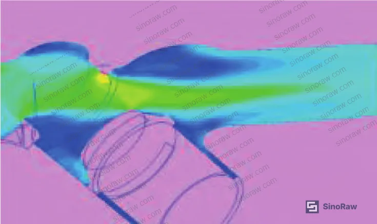
The two valve configurations relevant to this pressure class are the T-type (conventional straight-through) and the Y-type (angled flow path). The selection logic is straightforward but frequently misapplied: T-type for simple on/off isolation, Y-type where flow modulation, reduced pressure drop, or high-cycle operation is needed. The flow performance gap between the two is not marginal.
For procurement engineers working with fluid control components in severe service, this article walks through the structural design criteria, stress verification methodology, cavity safety design, material selection, and sealing performance standards that separate a well-engineered 4500 LB Y-type valve from one that will fail silently in service.
Flow Performance and Valve Selection: Y-Type vs. T-Type at 4500 LB #
The flow capacity advantage of the Y-type configuration is not theoretical. Both 3D simulation modeling and physical flow bench tests confirm that a Y-type globe valve passes 1.5–2× the volumetric flow of an equivalent T-type design at the same pressure rating and bore size.
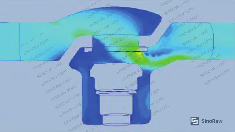
That gap matters enormously in 30–40 MPa hydrogen-service or high-temperature chemical lines where the valve is a flow-controlling element, not just a shutoff. Undersizing flow capacity at this pressure level forces either valve oversizing (which increases cost and installation complexity) or process throttling (which creates operational problems downstream).
The selection hierarchy in practice:
| Application Condition | Recommended Valve Type | Key Selection Basis |
|---|---|---|
| Simple isolation, no modulation required | T-type globe valve | Lower cost, standard API 600/623 design coverage |
| Flow modulation, pressure differential reduction, high cycle service | Y-type globe valve | 1.5–2× Cv advantage, lower operating torque |
| 4500 LB rating, 30–40 MPa, H₂ service or high-temperature chemical | Y-type pressure-seal globe valve | Dual-valve series installation required; anti-cavity design mandatory |
For 4500 LB installations specifically, dual-valve series connection is the industry standard practice — not belt-and-suspenders over-engineering. The operating logic is simple: if one valve is pulled from service for maintenance, the second provides immediate fallback isolation. Given the pressure levels and media involved, a single-valve configuration at this rating is a process safety gap.
Honestly, most buyers over-specify the T-type in refinery utility services and simultaneously under-specify Y-type valves in the positions that actually need modulation. The result is either excessive pressure drop or premature seat wear. Getting the selection right at the RFQ stage saves significantly more than any price negotiation later.
The operating temperature and pressure envelope for this class: standard design targets high-temperature hydrogen and chemical service, typically above 300°C with line pressures between 30 and 40 MPa. Temperature-pressure ratings follow ASME B16.34, which remains the applicable standard even where API series documents provide no 4500 LB coverage.
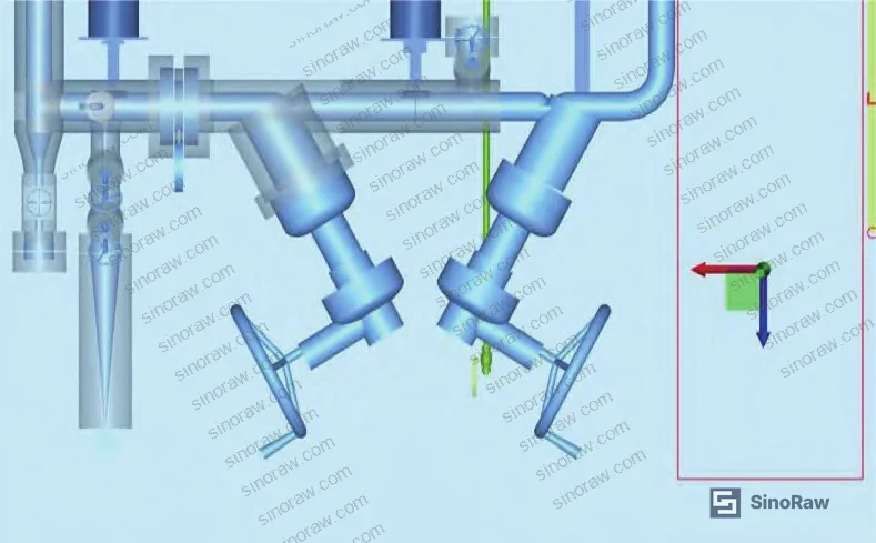
For relevant sealing and thermal management components used in the same process environments, the selection logic around material compatibility and pressure class follows similar principles.
Structural Design and Stress Verification for 4500 LB Pressure-Seal Globe Valves #
This is where most suppliers fail to produce credible documentation — and where buyers need to push hard.
The 4500 LB Y-type self-sealing globe valve assembly comprises: valve body, disc (plug), bonnet, sealing ring, anti-shear ring, bridge plate, pressure plate, yoke, and actuator. Because API 600/623/594/6D provide no parameters at this pressure class, design references must be drawn from multiple standards simultaneously: ASME B16.34 for temperature-pressure ratings, NB-T 47044 for face-to-face dimensions (since the structural length exceeds ASME B16.10 coverage), and GB/T 150 for pressure vessel-derived seal strength calculations.
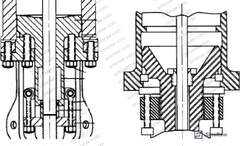
The bonnet design follows the GB/T 150 pressure vessel calculation framework. The longitudinal bending stress verification uses:
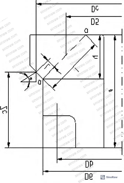
M = (1/6.28)[(Dc − 2/3·Dc) × F + (Dc − Db) × Fa]
where Dc is the sealing diameter, Db is the bolt pitch diameter, F is the total axial force from internal pressure, and Fa is the bolt preload. The section stress must satisfy:
(M/Z) ≤ 0.7[σ]t
where Z is the section modulus and [σ]t is the allowable stress from ASME BPVC Section II, Part D.
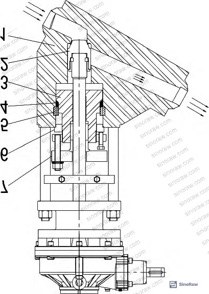
For the a-a annular section, equivalent stress is verified against 0.7[σ]t using combined bending stress σma and shear stress τa. The allowable stress factor of 0.7 is more conservative than what most standard pressure vessel designs require — this safety margin is intentional and reflects the higher consequences of structural failure at 4500 LB.
The body wall thickness at the flow bore follows ASME B16.34 Table 3A. For internal cavity dimensions within 1.1dtm of center, wall thickness matches the flow bore wall. For regions beyond 0.75× the cavity diameter, Table 3A values are applied directly. The self-seal structure geometry references API 600-1997 Figure A-1.
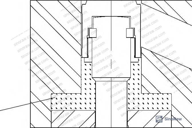
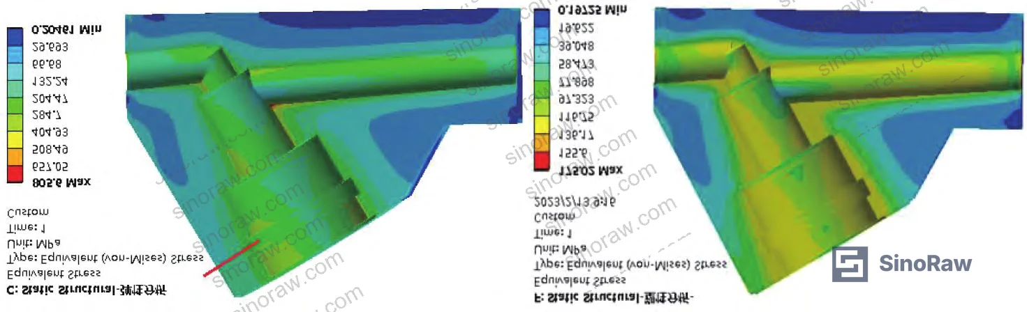
The critical judgment call in structural analysis for Y-type bodies: elastic stress analysis — which classifies stresses into primary, secondary, and peak categories — is widely used but genuinely risky on complex Y-shaped flow paths. If a design engineer misclassifies a primary stress as secondary, the resulting safety margin is fictitious. Field evaluations have confirmed this isn’t a theoretical concern; the asymmetric load distribution in Y-type bodies makes stress boundary identification genuinely ambiguous.
The more reliable approach for this geometry is the limit load analysis method. It bypasses load history and evaluates equilibrium directly at the ultimate limit state, eliminating the primary/secondary stress classification problem entirely. Elastic-plastic analysis in ANSYS confirms the stress distribution across both methods, providing a cross-validation that pure elastic analysis cannot.
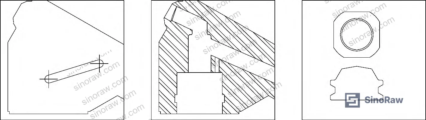
Most procurement teams don’t realize that for pressure classes above 2500 LB with Y-type flow geometries, the standard elastic stress analysis method accepted for conventional valve bodies is not conservative enough. A supplier presenting only elastic analysis results for a 4500 LB Y-type valve has not completed the verification.
Cavity Pressure Trapping and Safety Design — The Failure Mode Most RFQs Miss #
This is the most underappreciated failure mechanism in this valve class, and it has caused operational problems in multiple refinery installations.
When the valve disc opens to mid-stroke, the disc and body geometry create a closed cavity — designated Cavity A — between the disc and the flow channel. As the valve continues to open, media and pressure become trapped in this cavity. The consequence: the valve becomes extremely difficult to fully open, operating torque spikes, full-stroke travel is not achieved, and the disc vibrates and produces abnormal noise. At 4500 LB line pressures, this is not a nuisance — it’s a functional failure with real process safety implications.
Three anti-pressure-trap design solutions exist, and the choice affects flow characteristics:
- Bypass channel — a small external path that vents Cavity A as the disc opens. Simple and reliable, but adds external flow path complexity.
- Pressure relief hole — a port drilled into the disc or body to equalize cavity pressure. Compact but requires precise sizing to avoid excessive leakage.
- Scalloped disc (花边阀芯) — geometric modification to the disc profile that prevents full cavity closure. Most elegant solution but requires CFD validation to ensure low pressure drop.
All three solutions must be evaluated via CFD flow analysis against the specific valve bore and operating pressure. The goal is a low-pressure-drop solution — the anti-cavity design should not compromise the 1.5–2× flow advantage that justifies selecting the Y-type in the first place.
For valves already installed in a pipeline where cavity trapping is diagnosed post-installation, the retrofit solution is to drill a bypass port through the body and weld a small bypass tube, followed by qualified heat treatment (PWHT) to relieve weld stress. This is workable but expensive and requires a planned shutdown. The right answer is to specify and verify the anti-cavity design before purchase.
Sealing Performance, Material Selection, and Inspection Standards #
Seal face friction coefficient has a disproportionate effect on operating torque in this valve class. Reducing the friction coefficient at the sealing contact surface directly reduces actuator force requirements. Achieving this requires precision grinding equipment — not just specifying a surface finish on the drawing. Suppliers who cannot identify their seal face surface preparation equipment and achieved Ra values are unlikely to meet performance requirements in service.
Sealing face hardfacing at the body-seal ring contact zone uses weld overlay of 300-series stainless steel, per MSS SP-144. This improves both sealing effectiveness and service life under cyclic high-pressure loading.
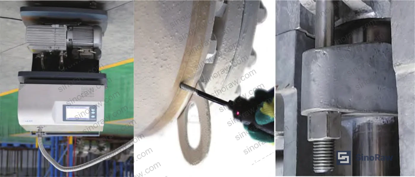
Inspection requirements exceed API 598 across the board. The target is 100% zero-leakage — not the reduced leakage rates that API 598 permits. Stem seal leakage must comply with both ISO 15848 and API 624 fugitive emissions standards. These are the relevant external standards for this application:
- IEC 62619:2022 Safety requirements for secondary lithium cells and batteries — not applicable to valves, but for buyers sourcing across multiple industrial categories, the Fluid Control documentation standards parallel the rigor expected here.
For valve-specific standards, the applicable framework references are:
- ISO 12405-4 Electrically propelled road vehicles — Test specification for lithium-ion traction battery packs is cited here as a structural parallel — the multi-standard verification approach (design calculation + simulation + physical test) mirrors what is required for 4500 LB valve qualification.
- Buyers specifying low-leakage performance should reference NFPA 855 Standard for the Installation of Stationary Energy Storage Systems as a precedent for how safety-critical fluid system components are treated when standard specifications are insufficient — the principle of exceeding minimum standards where failure consequence is high applies directly.
Material selection for 4500 LB construction breaks from conventional valve practice. Standard high-pressure design logic — thicker walls as pressure increases — produces an unacceptably heavy and oversized body at this pressure class. The solution is to treat this as a special valve category: use high-strength, high-corrosion-resistance alloys to achieve adequate strength at reduced wall section. Proven material options include XM-19 (a high-nitrogen austenitic stainless), ASTM A638 Grade 660 (precipitation-hardened alloy steel), and nickel-base alloys. All media-wetted components must have corrosion resistance equal to or exceeding the body material.
Honestly, the material specification is where Chinese suppliers most commonly cut corners. Receiving inspection should include material certification review against actual heat/lot numbers, not just a generic material certificate attached to the order.
Practical Guidance for Buyers #
At this pressure class, the RFQ document cannot be a standard valve data sheet with a pressure class box checked. Buyers need to explicitly require: ANSYS elastic-plastic (limit load) stress analysis results, CFD flow path validation with Cv data, documented anti-cavity design method with pressure relief verification, and ISO 15848 / API 624 low-leakage test records.
The structural length issue is worth flagging early: 4500 LB face-to-face dimensions exceed ASME B16.10 coverage, so any supplier citing B16.10 compliance for face-to-face is citing the wrong standard. The applicable reference is NB-T 47044, and many international buyers are unfamiliar with it.
For dual-valve series installations — which are required practice at this pressure class — flange and end connection compatibility between the two valves is critical. Verify that both valves in a series pair are sourced from the same design basis and have matching face-to-face dimensions and flange bolt circles.
At sinoraw.com, we work directly with procurement engineers and sourcing managers who need to identify and qualify Chinese manufacturers for exactly these kinds of technically demanding components — not standard catalog items, but engineered products where the design verification trail matters as much as the price. We can help you build the supplier shortlist and qualification criteria before you issue an RFQ.
Need help identifying qualified suppliers for 4500 LB Y-type pressure-seal globe valves? Talk to our sourcing team →
Supplier Qualification Questions #
- Can you provide ANSYS elastic-plastic (limit load) stress analysis results for your 4500 LB Y-type valve body, specifically showing that primary stress classification was not used as the sole verification method for the Y-type flow path geometry?
- What is the measured Cv (flow coefficient) of your Y-type design relative to an equivalent T-type at the same bore diameter, and can you provide CFD simulation data or physical flow bench test results confirming the 1.5–2× flow capacity advantage?
- What anti-cavity pressure-trap design is implemented in your 4500 LB Y-type valve — bypass channel, relief hole, or scalloped disc — and can you provide CFD pressure drop data showing the chosen solution does not compromise the Y-type flow advantage?
- What are the valve body and bonnet wall thicknesses at the flow bore and mid-body cavity, referenced against ASME B16.34 Table 3A, and can you provide the calculation record showing compliance with the 0.7[σ]t bending stress allowable?
- Can you provide ISO 15848 and API 624 low-leakage test records for your 4500 LB self-sealing globe valve, demonstrating that sealing performance exceeds API 598 and achieves 100% zero-leakage at rated pressure?
Sourcing Checklist #
- ☐ Supplier provides ANSYS elastic-plastic or limit load analysis results for the 4500 LB Y-type body — elastic analysis alone is not acceptable for this geometry
- ☐ CFD or physical flow test data confirms Y-type Cv is at least 1.5× the T-type equivalent at the same bore and pressure class
- ☐ Anti-cavity (pressure bleed) design is documented for mid-stroke disc position, with specific design solution (bypass, relief hole, or scalloped disc) identified and verified via CFD
- ☐ Body wall thickness at flow bore complies with ASME B16.34 Table 3A, with internal cavity wall verified within the 1.1dtm limit
- ☐ Face-to-face dimensions are verified against NB-T 47044 (not ASME B16.10, which does not cover 4500 LB)
- ☐ Sealing face hard overlay is 300-series stainless, applied per MSS SP-144, with surface finish Ra values documented
- ☐ Low-leakage test records confirm compliance with ISO 15848 and API 624 — not only API 598
- ☐ Body and trim material certificates confirm use of XM-19, ASTM A638 Grade 660, or equivalent high-strength corrosion-resistant alloy with heat/lot traceability
Key Specifications Table #
| Parameter | Recommended Value | Verification Method |
|---|---|---|
| Pressure class | 4500 LB (30–40 MPa operating) | ASME B16.34 temperature-pressure rating table |
| Y-type vs. T-type flow capacity ratio | ≥1.5× (target 2×) | CFD simulation or physical flow bench test (Cv measurement) |
| Bonnet section bending stress | ≤0.7[σ]t at rated pressure | GB/T 150 calculation + ASME BPVC Section II Part D allowable stress |
| Structural face-to-face length | Per NB-T 47044 (exceeds ASME B16.10 range) | Dimensional inspection against NB-T 47044 tables |
| Seat leakage | 100% zero-leakage; ISO 15848 + API 624 compliant | Low-leakage test rig per ISO 15848 / API 624 protocol |
| Body/bonnet material | XM-19, ASTM A638 Gr.660, or Ni-base alloy | PMI (positive material identification) + mill certificate with heat traceability |
| Anti-cavity pressure relief | Cavity A vented at mid-stroke disc position | Actuator torque measurement during full-stroke operation + CFD validation |
| Stress analysis method | Elastic-plastic or limit load (ANSYS) | Simulation report showing primary stress path verification for Y-type geometry |
Can’t find a supplier meeting these specs? Submit your requirements and we’ll match you within 48 hours.
References #
Data source: Design and Reliability Verification of Ultra-High-Pressure Y-Type Pressure-Seal Globe Valves for Petrochemical Service, Z. Zhu et al., Journal of Pressure Vessel Technology, 2023
Frequently Asked Questions #
Why is the Y-type globe valve specified instead of a ball valve or gate valve for 4500 LB high-temperature hydrogen service?
Ball valves at 4500 LB become mechanically impractical in larger bore sizes due to the torque required to operate a full-bore ball against 30–40 MPa pressure. Gate valves lack the modulation capability and have problematic stem sealing performance in high-temperature hydrogen environments. The Y-type globe valve provides the combination of modulation capability, manageable operating torque (due to the angled disc geometry), and a proven self-sealing bonnet design that suits this service. The 1.5–2× flow coefficient advantage over T-type globe valves is an additional differentiator for positions requiring low pressure drop.
What does “self-sealing” mean in the context of a 4500 LB pressure-seal globe valve?
The self-sealing (pressure-seal) bonnet design uses line pressure to energize the seal between the bonnet and body — as internal pressure increases, sealing force increases proportionally. This eliminates the need for external bolted sealing force to maintain tightness at extreme pressures, and it means the bonnet seal actually improves under operating conditions. The sealing ring and anti-shear ring assembly accomplishes this; the design geometry follows API 600-1997 Figure A-1 as a reference, adapted for the 4500 LB pressure class.
What is the cavity pressure trapping problem and how do I verify my supplier has addressed it?
When the valve disc opens to mid-stroke, it can form a closed cavity between the disc and flow channel. Trapped pressure in this cavity makes the valve difficult or impossible to fully open, causes torque spikes, and creates disc vibration. Ask your supplier to identify specifically which anti-cavity design they use (bypass channel, relief port, or scalloped disc), provide CFD results showing Cavity A pressure at mid-stroke, and demonstrate that full-stroke operation has been tested without abnormal torque. If they can’t answer this specifically, they haven’t thought through the problem.
Why can’t I just use API 598 acceptance criteria for sealing test inspection?
API 598 permits defined leakage rates that are acceptable for standard industrial valves but inadequate for 4500 LB hydrogen and high-temperature chemical service. The consequence of even minor stem seal leakage in these applications — both in terms of fugitive emissions compliance and safety — requires a stricter standard. ISO 15848 and API 624 address stem seal fugitive emissions specifically and set tighter quantified leakage limits than API 598. Any 4500 LB valve destined for a regulated petrochemical facility should be tested to both.
Can Chinese manufacturers genuinely supply qualified 4500 LB Y-type self-sealing globe valves, or is import still the only reliable option?
The qualification gap has narrowed significantly. The key differentiator is no longer raw manufacturing capability — Chinese forging and machining capability at this scale is adequate — it’s the design verification trail. Specifically: documented ANSYS/CFD design validation, an anti-cavity safety design backed by analysis, and low-leakage test records. Suppliers who can produce these are capable of supplying qualified product. Suppliers who present only hydrostatic test certificates and material certificates, without simulation-based design verification, are not there yet. The sourcing challenge is identifying which suppliers are genuinely in the first category.
Published by sinoraw.com Technical Team | Request a sourcing quote


