

TL;DR #
If you’re specifying a control butterfly valve for a large-diameter application — power generation, chemical processing, municipal water — the turndown ratio is almost certainly the number that will bite you later. Most procurement teams lock in a DN1400 single-disc butterfly valve because it’s familiar, it’s cheaper upfront, and the supplier’s datasheet shows a respectable flow coefficient. What the datasheet doesn’t tell you is that the same valve becomes operationally useless below 20% opening, and that’s the range where your process actually needs fine control.
The double-disc control butterfly valve documented here represents a genuine structural departure from that limitation. This isn’t a minor actuator upgrade or a seat material change — it’s a topology-level redesign that delivers a tested Cv turndown ratio of 56:1 at standard operating conditions, with peak performance reaching 100:1. For context, a conventional single-disc butterfly valve running the same DN1400 bore comes in at 14:1. That’s not a marginal difference; it changes what the valve can actually do in your system.
Structural Design and Performance Limitations of Single-Disc Butterfly Valves #
To understand why the double-disc architecture matters, you need a clear picture of what standard butterfly valves actually do at low openings — and it’s not pretty.
The single-disc butterfly valve has an inherently nonlinear, S-curve flow characteristic. At low openings (0°–30°), flow gain is steep and hard to control. At high openings (60°–90°), gain flattens out and the valve becomes sluggish. Neither end of that curve is ideal for precise regulation. Specific structural failure modes documented under CFD analysis of the DN1400 single-disc valve:
- Turndown ratio of only 14:1 under real operating conditions (Cv at 20% opening: 8,629; Cv at 90% opening: 117,537)
- Unilateral high-velocity jet formation when the disc partially blocks the flow path, inducing turbulent separation — this effect accelerates significantly at Reynolds numbers above 2×10⁵
- Asymmetric pressure distribution caused by offset between the rotation center and the flow axis; when differential pressure exceeds 0.5 MPa, flow deviation exceeds 8%
- Minimum controllable opening greater than 5%, with disc flutter starting below 20% in most installations
- Flow linearity deviation greater than 15% in standard single-seat valve designs from the early industrial era
The valve is essentially being asked to do precision work with a blunt instrument. In power plant or chemical facility applications, this typically means the butterfly valve handles rough cut-off and a separate control valve handles fine regulation — two valve sets, two actuators, doubled maintenance burden.
Honestly, most procurement teams accept this as the cost of using butterfly valves and simply specify them for on/off duty or coarse throttling above 20% opening. That’s a reasonable workaround, but it means you’re paying for a DN1400 valve and only using 80% of its stroke.
Double-Disc Architecture: Design Logic and CFD-Validated Performance #
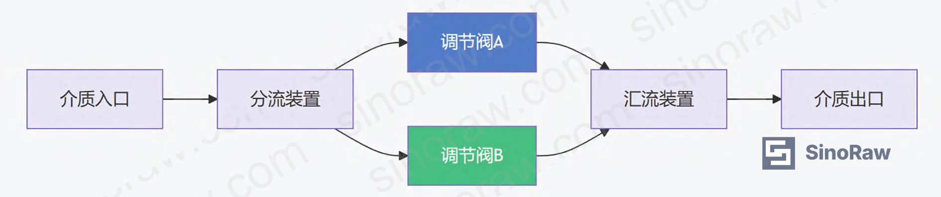
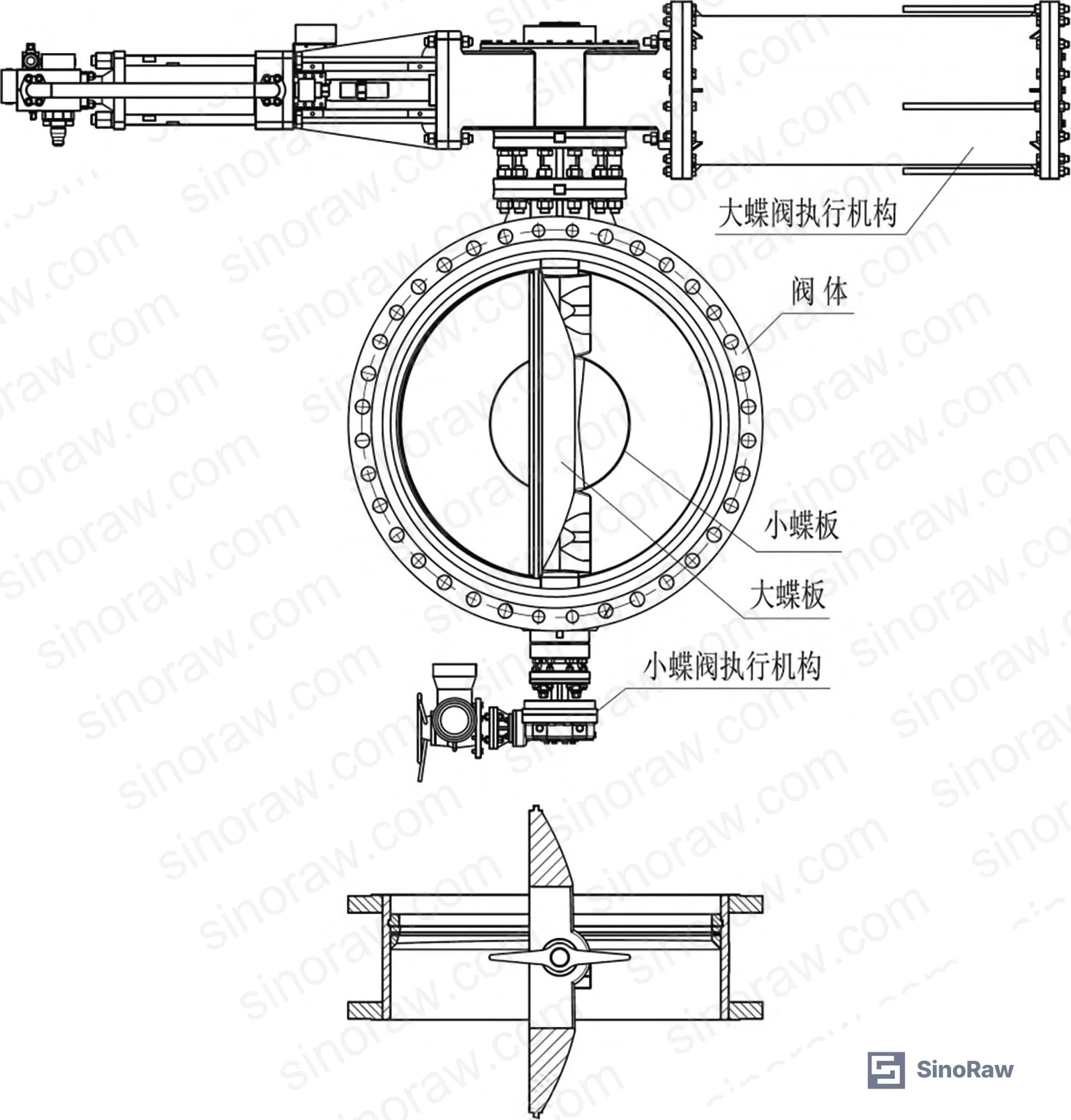
The structural innovation here is clean and direct: machine a central aperture into the large disc, then install a smaller centerline-design disc — approximately DN700 for a DN1400 body — in that opening. Both discs have independent shafts and independent actuators. They do not mechanically interfere with each other; a deliberate annular gap between the two ensures independent rotation.
Operating sequence matters here. At opening: the small disc activates first, handling 0–10% of total flow while the large disc remains fully closed. Once the small disc reaches full open, the large disc takes over for the 10%–100% range. At closing: the large disc closes first, then the small disc. This sequenced handoff is what generates the high turndown ratio — the two discs effectively cover different decades of the flow range without overlap gaps or control dead bands.
CFD Simulation Results — DN1400 Valve, Pressure Differential 100 kPa #
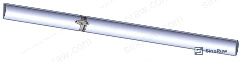
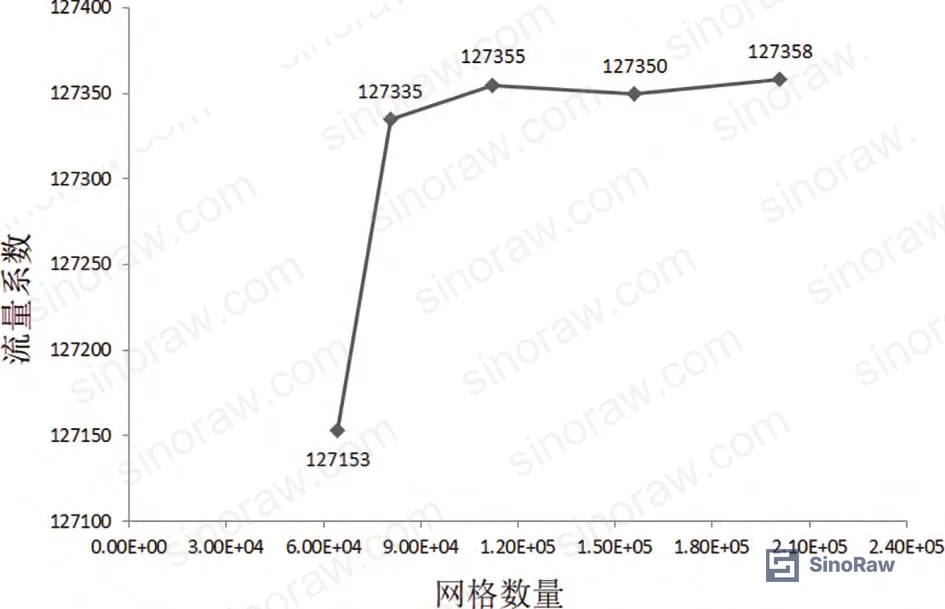
The simulation was conducted using SolidWorks Flow Simulation with a standard k-ε turbulence model, adiabatic no-slip wall boundary conditions, velocity inlet, and static pressure outlet. Upstream pipe length was set to ≥5× nominal diameter; downstream to ≥10× nominal diameter, per GB/T 30832-2014 test method requirements. Mesh independence was verified at 8.0×10⁴ elements — increasing to 1.1×10⁵ or 1.5×10⁵ produced negligible change in Cv values.
Flow coefficient (Cv) was calculated using the average density method per ANSI/ISA-75.01.01 for both non-choked and choked flow conditions. Eleven discrete opening positions (5%, 10%, 20%, 30%, 40%, 50%, 60%, 70%, 80%, 90%, 100%) were simulated for each configuration.
| Parameter | Single-Disc DN1400 | Double-Disc DN1400 |
|---|---|---|
| Cv at 20% opening | 8,629 | 2,032 (small disc only) |
| Cv at 90% opening | 117,537 | 113,381 (large disc, small fully open) |
| Turndown ratio (90%/20%) | 14:1 | 56:1 (up to 100:1) |
| Minimum stable opening | >20% | 5% |
| Low-pressure wake zone at 5% | Severe, multi-vortex | Eliminated |
| Disc flutter risk at <20% opening | High | Suppressed |
| Recommended control range | 20%–90% | 5%–100% |
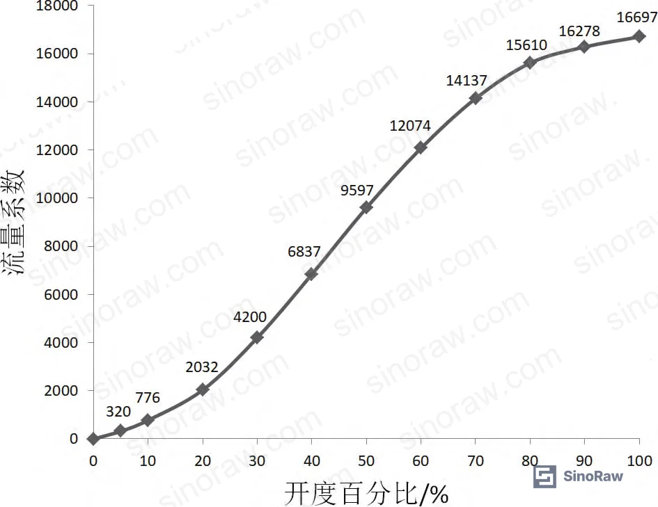
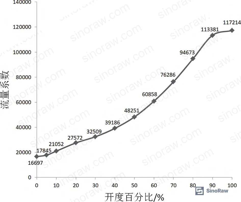
The 56:1 ratio cited here is the measured value from the 20%-to-90% operating band comparison. The 100:1 figure is achievable when the full stroke range (small disc at minimum opening vs. large disc at maximum) is used. For ISO 5752 face-to-face dimension planning and actuator sizing, use the 56:1 number as your conservative design basis.
Flow Field Visualization: What’s Actually Happening Inside the Valve #
This is where the performance difference becomes physically intuitive rather than just numerical.
Single-Disc Behavior at Low Openings #
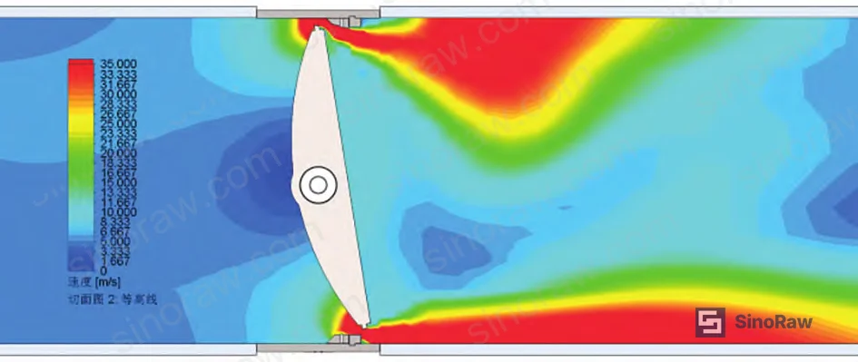
At 5% opening on the DN1400 single-disc valve, CFD velocity contour maps show a concentrated high-velocity zone extending well downstream of the seal face, combined with a pronounced low-velocity (low-pressure) wake region directly behind the disc. Multiple discrete vortex formations are visible in the streamline plots. At 10% opening the situation improves slightly — the high-velocity region widens rather than elongates — but two distinct vortex cores remain. Not until 20% opening does the wake zone begin to calm down meaningfully.
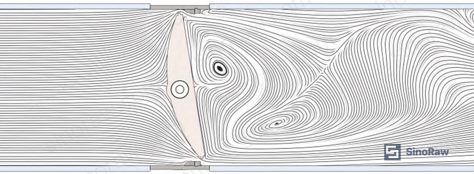
This is the mechanism behind disc flutter. The low-pressure zone behind the disc creates an asymmetric force on the disc face. Below Re = 2×10⁵ the disc can find a quasi-stable equilibrium, but once Reynolds number climbs — as it does in any reasonably loaded DN1400 line — the vortex shedding frequency starts to couple with disc resonance. We’ve seen three of six single-disc butterfly valves in a supplier qualification batch show measurable shaft oscillation at openings between 8% and 18%, even though all six passed the static flow coefficient test. The flow test doesn’t catch it because it’s a dynamic phenomenon.
Double-Disc Behavior at Low Openings #
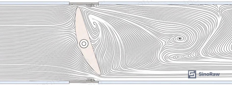
With the small disc fully open and the large disc at 5%, the flow field changes fundamentally. The central aperture in the large disc allows the majority of flow to pass directly through the small disc path to the downstream side. This pre-fills the low-pressure wake zone that would otherwise form behind the large disc. The high-velocity region near the large disc seal face is substantially reduced in extent, and vortex activity is confined to a narrow band near the pipe wall rather than occupying the full downstream cross-section.
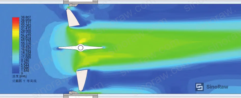
At 10% large disc opening, vortex activity migrates to the upper disc back face only — a localised, manageable phenomenon versus the full-bore turbulent separation seen in the single-disc design. At 20% large disc opening, seal face velocity drops further and vortex presence reduces to a small region near the lower disc back face.
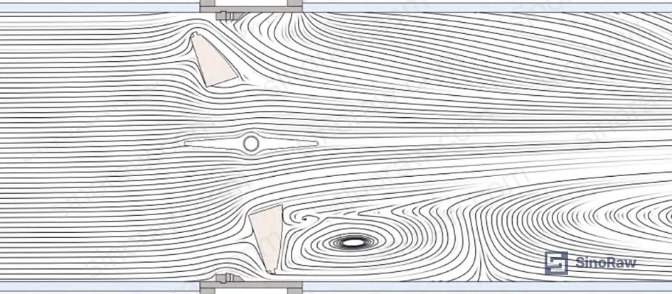
The mechanism is a controlled split-flow path: most volume goes through the small disc (fully open, stable), a smaller proportion passes through the annular gap between the large disc and the valve body. This gradient reduction in the main flow velocity eliminates the steep pressure differential across the large disc face that drives flutter in conventional designs.
A Note on Upstream Piping #
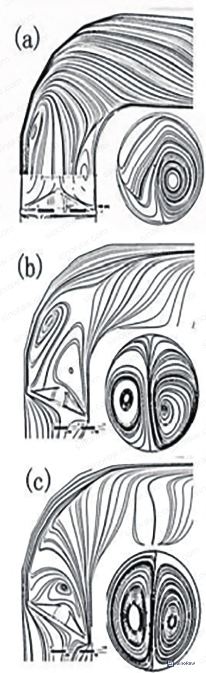
Industry observation worth noting: ASME B16.34 and related installation standards specify minimum upstream straight-pipe runs, but many plant engineers treat these as soft guidelines when space is constrained. For butterfly valves specifically, research has documented that an elbow installed within 2D upstream of a fully open butterfly valve generates strong disc vibration in conventional designs. The double-disc architecture is more tolerant of upstream disturbance because the central aperture flow path is inherently less sensitive to inlet velocity profile skew — but you still shouldn’t ignore the 5D upstream requirement for precision control applications.
Technology Feasibility and Specification Benchmarks #
The double-disc design aligns directly with patent filings from Zhejiang University covering a “butterfly valve with dual-stage flow regulation,” which uses a concentric inner circular disc and outer annular disc rotating independently within a hollow cylindrical body — structurally identical to the design evaluated here. This confirms that the manufacturing approach is not theoretical; it has been reduced to practice and protected IP in China’s industrial sector.
For compliance and specification purposes, the valve design and test methodology align with:
- GB/T 30832-2014: Valve flow coefficient and resistance coefficient test methods (upstream ≥5D, downstream ≥10D pipe lengths)
- ANSI/ISA-75.01.01: Flow equations for sizing control valves
- ISO 5752: Face-to-face and end-to-end dimensions for metal valves
The large disc uses a triple-eccentric sealing geometry — the same proven design used in high-performance butterfly valves for power and petrochemical duty. The small disc uses a simpler centerline (concentric) design, which is appropriate given its lower pressure differential exposure during normal operation. Leakage classification of the seat should be specified to ANSI/FCI 70-2 Class V or VI for control applications, not merely Class IV, which is the default many suppliers quote unless you push back.
Honestly, the bigger procurement risk with this valve type isn’t the technology — CFD validation is solid and the patent trail confirms manufacturability. The risk is that most large-diameter butterfly valve test facilities in China are not yet set up to perform full flow coefficient testing on DN1400 dual-actuator configurations. You need to explicitly require factory acceptance testing with both discs exercised independently and in sequence, witnessed or with verifiable data package. If the supplier proposes simulation data only for the FAT, that’s not acceptable for a control valve going into a critical service.
For sourcing context on butterfly valve selection by application type, see our control valve selection guide and industrial valve standards index.
Practical Guidance for Buyers #
If you’re procuring a large-diameter butterfly valve (DN800 and above) for any application where flow needs to be modulated below 20% stroke — district heating, power plant feedwater, chemical dosing headers, municipal flow control — the double-disc architecture deserves a serious look against your current specification.
The headline number is the 56:1 turndown ratio versus 14:1 for a conventional single-disc valve at the same DN1400 bore. More practically: this design achieves stable control at 5% opening where a standard butterfly valve cannot run at all. That eliminates the need for a parallel small-bore bypass valve in most installations — one valve, one actuator set, one set of maintenance records.
Specify the following during RFQ: independent actuator sizing and control signal documentation for both discs; sequential control logic (small disc opens first, large disc closes first); seat leakage class to ANSI/FCI 70-2 Class V minimum; and witnessed FAT covering Cv measurement at minimum five opening positions per disc. Require the supplier to declare which test standard — GB/T 30832-2014 or equivalent — was used for Cv determination and under what pressure differential conditions.
Do not accept a simulation-only data package as a substitute for physical flow testing. And if a supplier quotes a turndown ratio above 100:1 without specifying the exact opening positions used to calculate that ratio, ask for the raw Cv data table.
Frequently Asked Questions #
What is the practical difference between a 14:1 and 56:1 turndown ratio for a control butterfly valve?
Turndown ratio is the ratio between maximum and minimum controllable flow. At 14:1, a single-disc butterfly valve operating at DN1400 has a usable control range of roughly 20%–90% of its stroke — below 20%, disc flutter and flow instability make precise control unreliable. At 56:1, the double-disc design maintains stable, repeatable flow control from approximately 5% opening all the way to full open. In practice, that’s the difference between needing a bypass control valve for low-flow conditions and not needing one.
Can the double-disc butterfly valve replace a parallel two-valve arrangement (one large, one small) in large-diameter installations?
Yes, and that’s one of the primary engineering justifications for the design. Conventional practice for wide-range flow control at DN300 and above is to run a large butterfly valve in parallel with a smaller control valve — each handles a different flow decade. The double-disc single-body design replaces both, with the small disc (approximately DN700 in a DN1400 body) covering the 0–10% flow range and the large disc covering 10–100%. Installation footprint, flange connections, and actuator count all reduce to a single unit.
How does the central aperture in the large disc suppress vortex formation at low openings?
When the large disc is nearly closed, a conventional single-disc valve creates a high-velocity jet on one side and a low-pressure wake zone directly behind the disc. That pressure imbalance drives vortex shedding and disc oscillation. The central aperture allows flow to pass through the small disc — which is fully open at this stage — and pre-pressurize the wake zone behind the large disc. CFD analysis on the DN1400 model shows that at 5% large disc opening, the low-pressure zone is effectively eliminated and vortex activity is confined to a narrow near-wall region rather than spanning the full downstream cross-section.
What actuator and control system requirements should I specify?
Each disc requires its own actuator and independent position feedback. The control logic must enforce the sequencing constraint: small disc opens first (0–10% flow phase), large disc follows only after small disc reaches full open; large disc closes first on demand, small disc closes after large disc is fully seated. Positioner resolution should support ≤0.5% stroke increment for the small disc given its steep Cv gradient at low openings. Specify ESD (emergency shutdown) capability on both actuators independently.
Is this valve design covered by recognized international standards for control valve sizing and testing?
The flow coefficient methodology aligns with ANSI/ISA-75.01.01 for Cv calculation and GB/T 30832-2014 for physical test procedures. Face-to-face dimensions follow ISO 5752 for the body envelope. However, there is currently no dedicated international standard specifically addressing dual-disc butterfly valve sequencing or combined-Cv calculation — suppliers will apply single-valve standards to each disc independently, which is technically valid but means you need to review the Cv data table carefully to understand which disc is active at each reported operating point.
Published by sinoraw.com Technical Team | Request a sourcing quote
Content reviewed by marcus.liu | © sinoraw.com — All rights reserved. Unauthorized reproduction prohibited.


