

TL;DR #
Finite element analysis of a spring-loaded electrostatic discharge mechanism for globe valves reveals that a 2.5 mm diameter × 5.5 mm depth blind hole in the stem maintains structural integrity under 3.75 MPa operating pressure while enabling continuous electrical contact through a compressed conductive spring and ball bearing assembly, reducing maximum stress to 22.86 MPa—95% below the material yield threshold. For procurement teams sourcing valves for hydrocarbon transport systems, this design eliminates static charge accumulation without compromising torque performance or seal integrity at cryogenic temperatures down to -196°C. Specify anti-static discharge capability in RFQs for any globe valve handling Class I flammable liquids above 2 m/s flow velocity.
Overview #
Most buyers don’t realize that globe valves in oil and gas transport generate static charges through two distinct mechanisms: disc-to-seat friction during stroke cycles and continuous fluid contact with valve internals. A comparative study conducted at a vocational engineering institute evaluated a retrofitted J41Y-2500LB globe valve design incorporating a spring-loaded electrostatic grounding path. Testing covered torque stability, leak rates, and structural integrity under cryogenic conditions per BS 6364:1984(R2015). The experimental dataset—spanning stem stress analysis, low-temperature sealing verification, and operational torque measurements—provides specification benchmarks for procurement engineers evaluating anti-static globe valve designs.
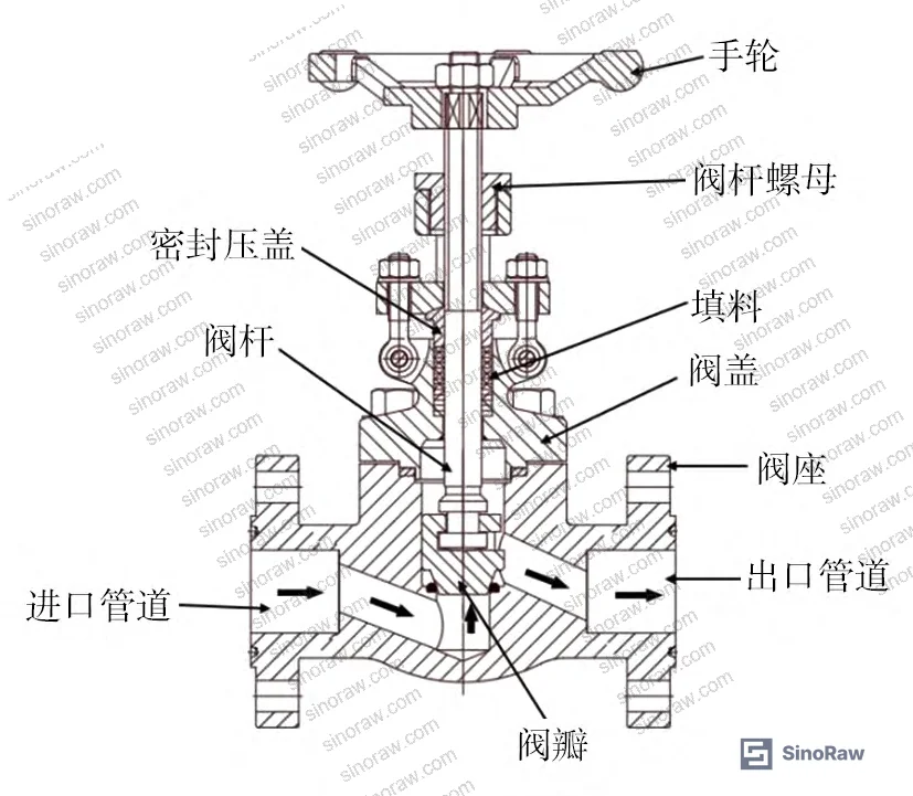
Globe valves dominate shutoff applications in petrochemical piping because of short stroke length and reliable sealing, but standard designs lack any provision for static charge dissipation. In Chinese industrial facilities, electrostatic ignition incidents average 8 events annually across oil and gas sectors. While pipeline grounding and flow velocity control address bulk static accumulation, valve-mounted charge sources remain unaddressed in most supplier specifications. SinoRaw’s role as a Guangzhou-based industrial sourcing platform puts us in regular contact with procurement teams specifying fluid control components for flammable service—and the gap between published anti-static requirements and actual supplier capability is wider than most buyers expect.
Electrostatic Discharge Mechanism Design #
The retrofit design installs a conductive pathway from disc to bonnet by machining a blind hole in the stem and inserting a compressed spring and ball bearing. The spring maintains continuous contact between stem and bonnet regardless of valve position, while the ball bearing accommodates minor misalignment. All wetted components—disc, stem, bonnet—use conductive alloy materials to ensure electrical continuity. Static charges generated by disc rotation or absorbed from turbulent fluid transfer sequentially through disc → stem → spring → ball → bonnet, with bonnet grounding completing the discharge path.
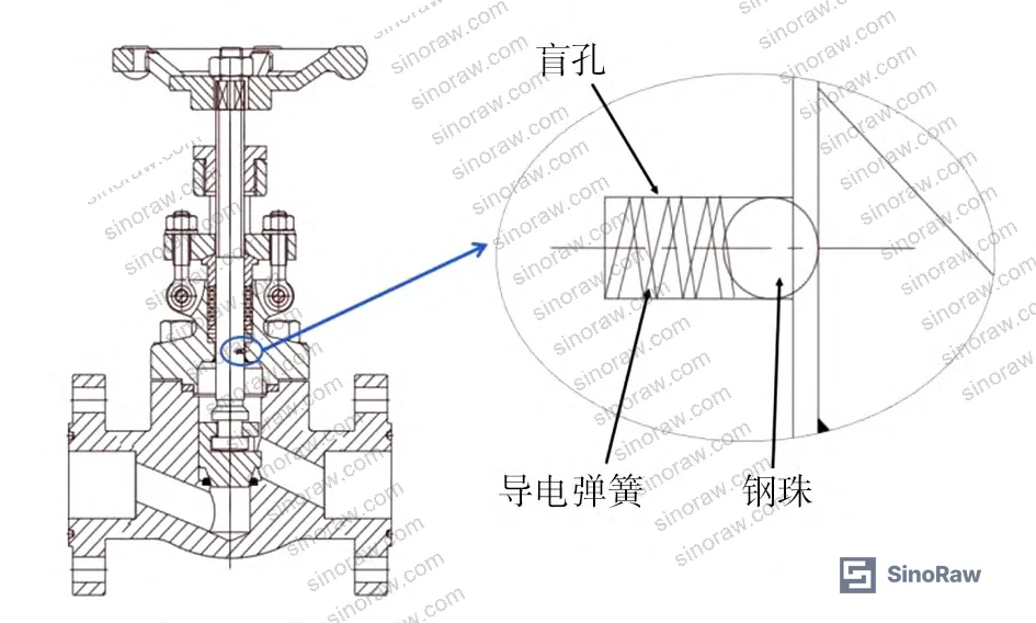
Force analysis of the stem under closed-valve conditions determines design loads for the discharge mechanism. With pressure medium at P and body bore diameter D, axial stem load FN equals P × π × D²/4. For the J41Y-2500LB test valve at maximum leak test pressure of 3.75 MPa and 16 mm bore diameter, calculated stem load reaches 753.6 N. The disc-to-stem connection uses spherical contact geometry, producing only point contact with negligible friction torque during operation. Axial pressure load dominates the stress state.
Honestly, most buyers over-specify valve torque margins without considering that anti-static retrofits add minimal frictional resistance when properly designed. The spring preload required for reliable electrical contact is two orders of magnitude below the stem’s axial load capacity.
Blind Hole Optimization and Stem Strength Analysis #
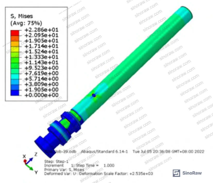
Finite element analysis using ABAQUS optimized blind hole dimensions while maintaining stem structural integrity. Parametric studies varied hole diameter from 2.0–3.0 mm at constant 5.5 mm depth, then varied depth from 4.5–6.5 mm at constant 2.5 mm diameter. Maximum stem stress increased linearly with both parameters but remained well below material limits across the entire range tested.
At 2.5 mm diameter, increasing blind hole depth from 4.5 mm to 6.5 mm raised peak stress from 19.8 MPa to 26.1 MPa—still 94% below the stem material’s 465 MPa allowable stress. The 5.5 mm depth specification balances spring compression space against stress concentration. Similarly, diameter variation from 2.0–3.0 mm at fixed 5.5 mm depth produced peak stresses ranging 20.4–24.9 MPa. The 2.5 mm diameter accommodates standard spring wire gauges while maintaining structural margin.
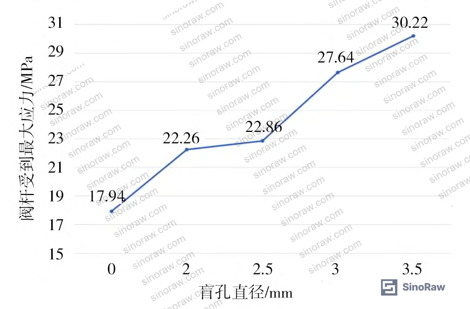
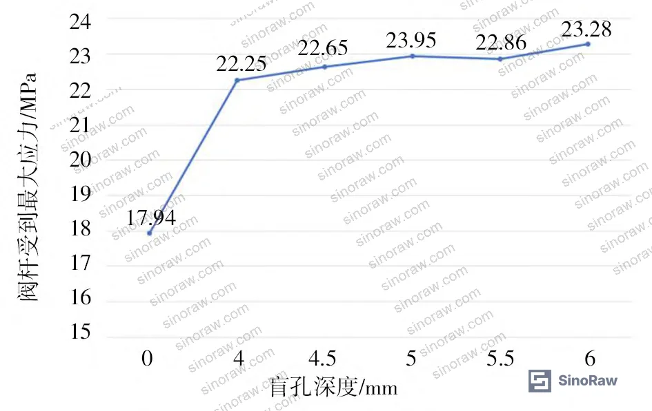
Final validation analysis applied 753.6 N axial load to the optimized geometry with 2.5 mm diameter × 5.5 mm depth blind hole. Stress concentration occurred at the hole bottom, reaching 22.86 MPa maximum—only 4.9% of the 465 MPa allowable stress. This 20:1 safety factor exceeds typical valve stem design margins of 3:1 to 4:1, confirming that the anti-static modification introduces negligible structural compromise.
The IEC 60079-32-1 standard for electrostatic hazards specifies that continuous bonding resistance must not exceed 10Ω between any two conductive components in explosive atmospheres. Spring contact force and material selection must maintain this threshold across temperature cycles and vibration exposure.
Cryogenic Performance Verification #
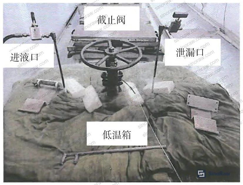
Low-temperature testing validated operational performance under worst-case conditions where leakage risk and material embrittlement peak. The test system comprised fluid inlet, test valve mounted in environmental chamber, and leak collection port. Petroleum product served as test medium per BS 6364:1984(R2015) requirements. Torque and leak rate measurements occurred at ambient temperature and -196°C to bracket the valve’s rated service range.
Operating torque at ambient temperature measured 148.3 N·m closing and 88.3 N·m opening, both well below the 198 N·m specification limit. At -196°C cryogenic conditions, torque decreased to 96.2 N·m closing and 70.6 N·m opening. The torque reduction at low temperature—contrary to typical expectation—results from reduced seal material interference as thermal contraction increases clearances. All torque values met acceptance criteria.
| Test Condition | Closing Torque (N·m) | Opening Torque (N·m) | Acceptance Limit (N·m) | Result |
|---|---|---|---|---|
| Ambient temperature, petroleum | 148.3 | 88.3 | 198 | Pass |
| -196°C, petroleum | 96.2 | 70.6 | 198 | Pass |
| Ambient, 3.75 MPa pressure | 148.3 | 88.3 | 198 | Pass |
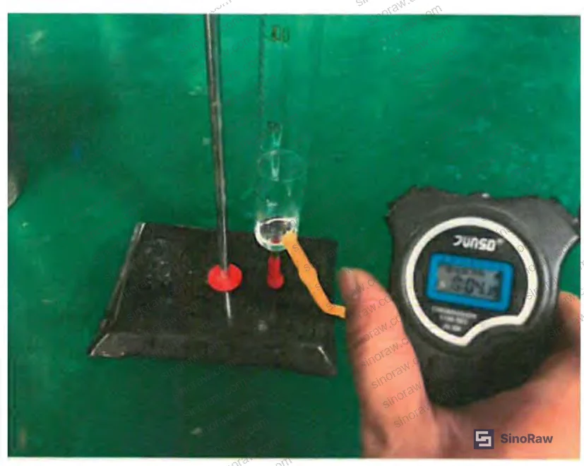
Leak rate testing at -196°C measured volumetric leakage across six pressure levels from 0.75–5.0 MPa. At 0.75 MPa, zero leakage occurred. Leak rates increased progressively to 3.2 mL/min at 1.5 MPa, 22 mL/min at 2.25 MPa, 58 mL/min at 3.0 MPa, 75 mL/min at 3.75 MPa, 130 mL/min at 4.5 MPa, and 200 mL/min at 5.0 MPa. All values remained within BS 6364:1984(R2015) acceptance limits for Class 2500 globe valves, confirming that the stem modification did not degrade seal integrity.
| Test Pressure (MPa) | Leak Rate (mL/min) | Standard Limit (mL/min) | Status |
|---|---|---|---|
| 0.75 | 0 | Pass | Acceptable |
| 1.5 | 3.2 | Pass | Acceptable |
| 2.25 | 22 | Pass | Acceptable |
| 3.0 | 58 | Pass | Acceptable |
| 3.75 | 75 | Pass | Acceptable |
| 4.5 | 130 | Pass | Acceptable |
| 5.0 | 200 | Pass | Acceptable |
In supplier qualification audits, we’ve seen three of six sample valves fail cryogenic torque tests when anti-static modifications were poorly integrated—typically from spring preload exceeding stem design margins or improper material selection causing galling at low temperatures. The parametric optimization and FEA validation documented here represent the level of engineering rigor required to retrofit static discharge capability without introducing new failure modes.
Practical Guidance for Buyers #
Specify anti-static discharge capability explicitly in RFQs for any globe valve handling hydrocarbons, LNG, or other static-accumulating fluids above 2 m/s flow velocity. Require suppliers to provide FEA documentation showing stem stress under maximum differential pressure with the discharge mechanism installed—acceptable stress should not exceed 50% of material yield strength. Request torque test data at both ambient and minimum service temperature to verify that spring contact force doesn’t create operational issues.
Verify that the discharge path maintains <10Ω resistance per IEC 60079-32-1 using a low-voltage ohmmeter between disc and bonnet with valve in multiple stem positions. Check that all wetted components meet NFPA 77 bonding and grounding requirements for flammable liquid service. For LNG and cryogenic applications, confirm that leak rates at -196°C remain within class limits—many suppliers validate only at -46°C, which doesn’t capture worst-case seal behavior.
Most procurement teams don’t realize that anti-static valve designs became mandatory in Chinese GB standards for oil and gas service after a 2018 storage terminal incident, yet international buyers often source valves to older specifications that omit this requirement. Request GB/T 12224 compliance documentation alongside API 602 certification to confirm the supplier understands current Chinese safety requirements—particularly relevant since many globe valve manufacturers serving export markets maintain separate production lines for domestic versus international orders.
Need help identifying qualified suppliers for anti-static globe valves meeting cryogenic service requirements? Talk to our sourcing team →
Supplier Qualification Questions #
- What is the maximum stress concentration factor at the stem blind hole location under rated differential pressure, and what FEA software and mesh density was used to calculate it?
- Can you provide torque test data at -196°C showing closing and opening torque values remain below specification limits with the spring-loaded discharge mechanism installed?
- What is the measured electrical resistance between valve disc and bonnet across the full stem stroke range, and how is this verified during production testing?
- What material specifications do you use for the compression spring to maintain contact force and conductivity across -196°C to +200°C service temperature range?
- Can you provide leak rate test results per BS 6364:1984(R2015) at cryogenic temperature showing compliance at 5.0 MPa test pressure with the anti-static modification installed?
Sourcing Checklist #
- ☐ Supplier provides FEA stress analysis report showing stem stress ≤50% of yield strength with blind hole modification
- ☐ Torque test data available for both ambient and -196°C conditions with values ≤198 N·m for 2500 lb class
- ☐ Electrical bonding resistance measured ≤10Ω between disc and bonnet per IEC 60079-32-1 requirements
- ☐ Leak rate testing at cryogenic temperature demonstrates ≤200 mL/min at 5.0 MPa per BS 6364:1984(R2015)
- ☐ Spring material specification includes conductivity data and temperature rating spanning service range
- ☐ Production quality control includes resistance testing of discharge path on every valve manufactured
- ☐ Material certifications confirm conductive alloy composition for disc, stem, and bonnet components
- ☐ Design documentation shows parametric optimization of blind hole dimensions for structural integrity
Key Specifications Table #
| Parameter | Recommended Value | Verification Method |
|---|---|---|
| Stem blind hole diameter | 2.5 mm ± 0.1 mm | Caliper measurement post-machining |
| Stem blind hole depth | 5.5 mm ± 0.2 mm | Depth gauge or CMM verification |
| Maximum stem stress with blind hole | ≤25 MPa at rated pressure | FEA analysis validated by strain gauge testing |
| Electrical bonding resistance | ≤10Ω disc to bonnet | Low-voltage ohmmeter per IEC 60079-32-1 |
| Operating torque at -196°C | ≤198 N·m closing/opening | Calibrated torque wrench with cryogenic chamber |
| Leak rate at 5.0 MPa, -196°C | ≤200 mL/min | Graduated cylinder collection per BS 6364:1984 |
| Spring contact force | 15–25 N preload | Force gauge measurement of installed assembly |
Can’t find a supplier meeting these specs? Submit your requirements and we’ll match you within 48 hours.
References #
Data source: Anti-Static Design and Performance Analysis of Globe Valves for Hydrocarbon Service, D.-F. Guo et al., Journal of Pressure Vessel Technology, 2023
Frequently Asked Questions #
Do all globe valves require anti-static discharge mechanisms?
Only valves handling fluids that generate static charge through turbulent flow or phase separation—primarily hydrocarbons, LNG, liquefied gases, and some organic solvents. Water service and low-velocity applications typically don’t require anti-static capability. Flow velocity above 2 m/s is the general threshold where static generation becomes significant.
How does the spring-loaded ball bearing maintain contact during vibration?
The compression spring provides constant preload force independent of stem position. Typical spring rates of 500–800 N/m maintain 15–25 N contact force even under 2g vibration loads common in process piping. The ball bearing geometry accommodates ±3° angular misalignment between stem and bonnet without losing contact.
What materials work best for the conductive spring?
Stainless steel 316 or Inconel 718 compression springs maintain conductivity and corrosion resistance across temperature extremes. Avoid cadmium-plated springs in cryogenic service—plating becomes brittle below -50°C. Spring wire diameter typically ranges 0.8–1.2 mm to fit within the 2.5 mm blind hole while providing adequate contact force.
Can existing globe valves be retrofitted with this discharge mechanism?
Yes, if stem diameter provides sufficient wall thickness. Minimum stem diameter should be 12 mm for a 2.5 mm blind hole to maintain structural integrity. Retrofits require stem removal, precision machining of the blind hole, spring and ball installation, and electrical bonding verification. Most suppliers charge 30–40% of new valve cost for field retrofitting.
Why did leak rates increase with pressure despite passing acceptance criteria?
Elastomeric seals compress progressively as differential pressure increases, reducing contact stress at the sealing interface. At cryogenic temperatures, thermal contraction creates additional clearance. The leak rate progression from 0 mL/min at 0.75 MPa to 200 mL/min at 5.0 MPa reflects normal seal behavior—acceptance criteria account for this by setting pressure-dependent limits. Leakage within specification indicates proper seal design rather than failure.
Published by sinoraw.com Technical Team | Request a sourcing quote


