

TL;DR #
Across 235 DN15 cryogenic shutoff valve specimens tested at −196°C, packing gland temperatures followed a normal distribution centered near 8.5°C — confirming that a properly designed extended-bonnet LNG globe valve can maintain above-freezing packing conditions even at liquid nitrogen immersion temperatures. For buyers, this means packing temperature margin above 0°C is a quantifiable, verifiable acceptance criterion — not just a design claim — and suppliers who cannot provide parametric simulation data alongside physical test results should be treated with skepticism. Before issuing an RFQ for LNG cryogenic valves, require suppliers to demonstrate both physical temperature field test data from ≥200 valve samples and validated FEA results showing packing gland temperature >0°C under worst-case convective conditions.
Overview #
Cryogenic shutoff valves for LNG service are one of those components where a marginal supplier passes all the paperwork checks and still fails in the field — because the critical failure mode, packing seal degradation from stem cold-migration, doesn’t show up in a room-temperature hydrostatic test. The only way to truly qualify a valve for −196°C LNG service is to run it immersed in liquid nitrogen and measure where the temperature actually stabilizes in the packing zone.
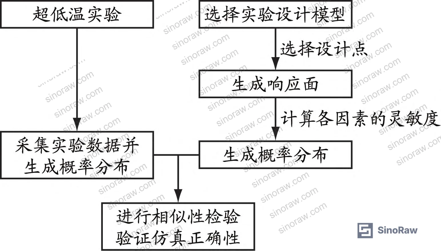
The data underlying this analysis comes from a controlled cryogenic temperature field study conducted by a shipbuilding valve manufacturer in collaboration with a maritime engineering university. The study collected packing gland temperature readings from 235 DN15 ultra-low-temperature globe valves under standardized immersion conditions — one of the larger empirical datasets in this specific component category. Critically, the researchers didn’t stop at raw measurements: they used parametric finite element analysis to isolate the contribution of three independent variables — convective heat transfer coefficient, nitrogen vapor layer height, and nitrogen layer temperature — to the final packing zone temperature. That parametric approach is what makes this data genuinely useful for procurement specification writing, because it tells you which site and installation conditions can push a marginal valve into failure.
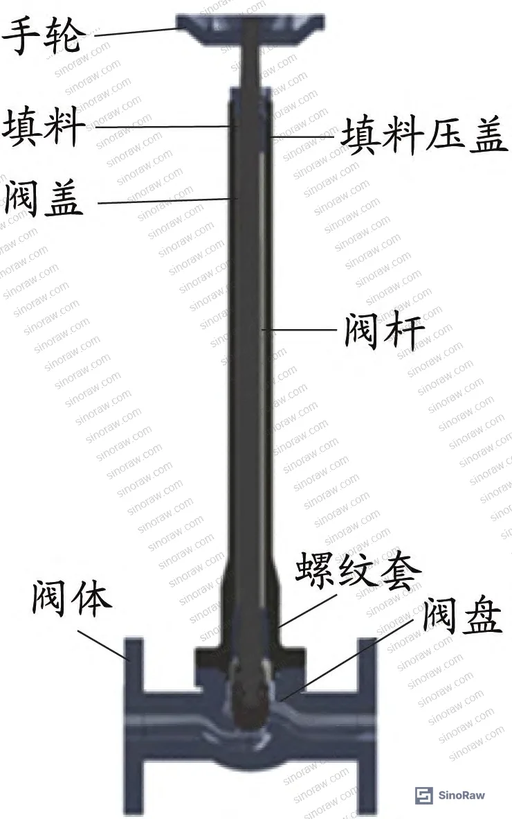
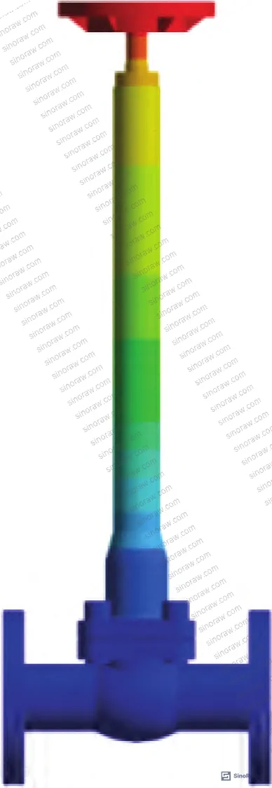
The DN15 flange-end globe valve tested uses ASME B16.5 connection dimensions, with body and bonnet in 316L stainless steel. The packing material is flexible graphite (thermal conductivity 151 W/(m·K), specific heat capacity 709 J/(kg·K)), and the seat sealing surfaces use Stellite 6 hard-facing alloy with a thermal conductivity of 20 W/(m·K). These material choices are standard for LNG cryogenic service and serve as a useful benchmark when evaluating supplier material certificates.
Cryogenic Packing Temperature Distribution: What the Test Data Actually Shows #
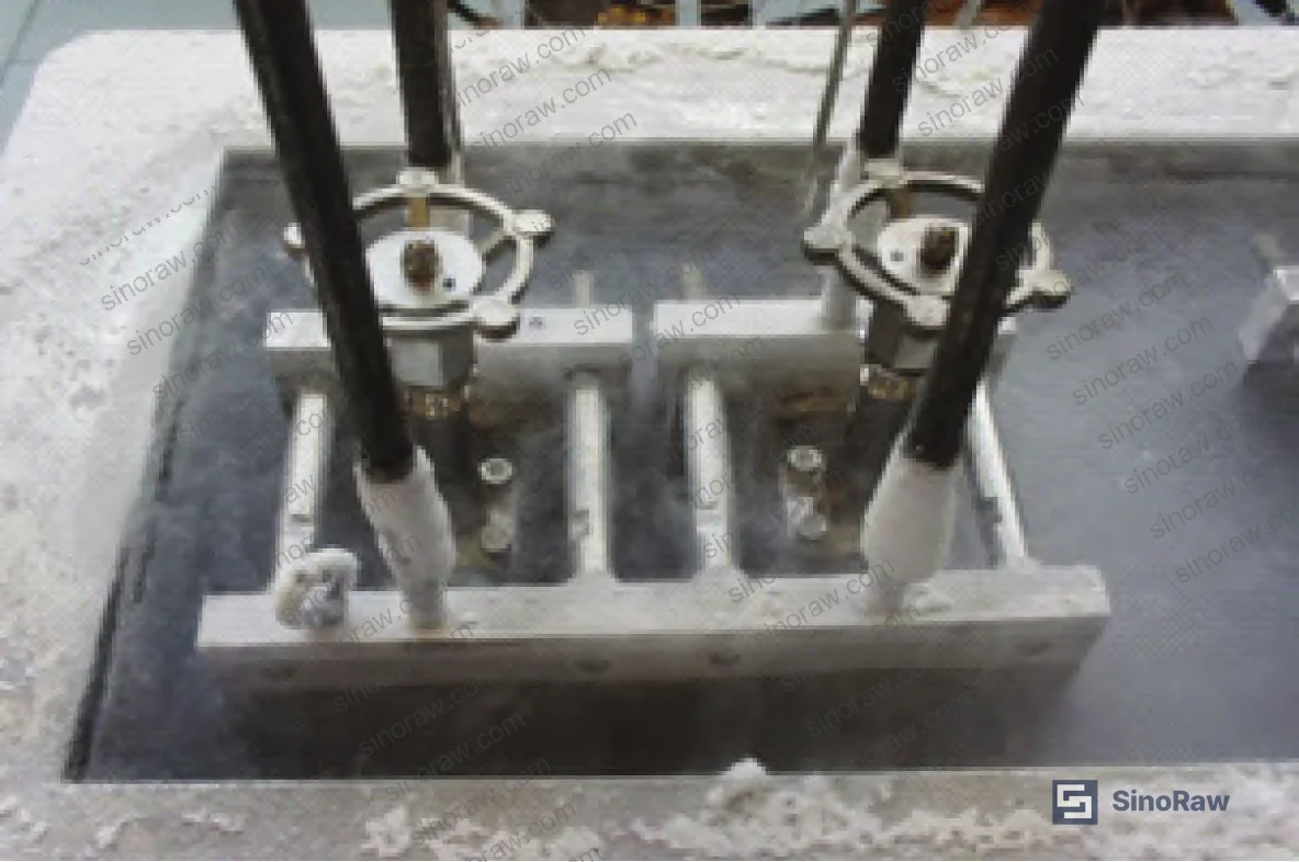
The test protocol is straightforward but demanding: valves are fully immersed in liquid nitrogen with the liquid level reaching the junction of body and bonnet, held for a minimum of 1 hour, and temperature recording begins only after the coolant stops boiling and both bonnet and body temperatures approach −196°C. Ambient temperature during all testing was held at 22–23°C. Any supplier who quotes “cryogenic tested” without specifying immersion depth, soak duration, and the stabilization criterion is describing a much weaker test than this.
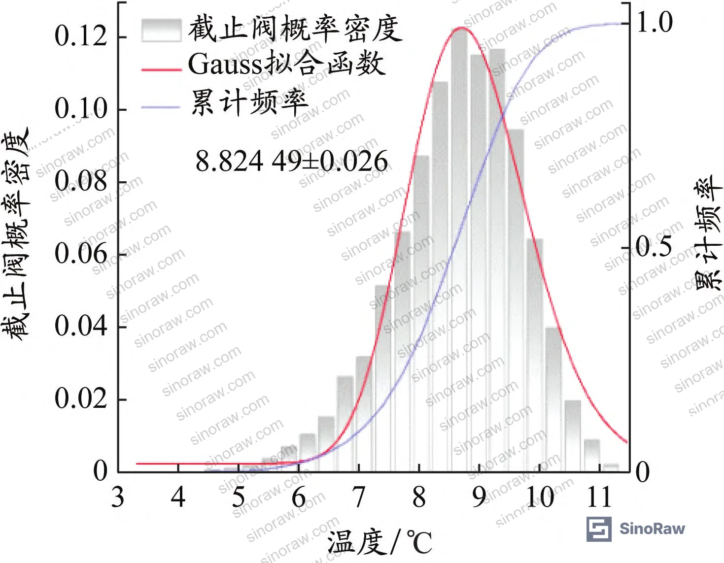
The 235-sample packing temperature dataset breaks down as follows:
| Packing Temperature Range (°C) | Number of Valves | % of Total |
|---|---|---|
| 3–5 | 4 | 1.7% |
| 5–7 | 40 | 17.0% |
| 7–9 | 85 | 36.2% |
| 9–11 | 76 | 32.3% |
| 11–13 | 27 | 11.5% |
| 13–15 | 3 | 1.3% |
| Total | 235 | 100% |
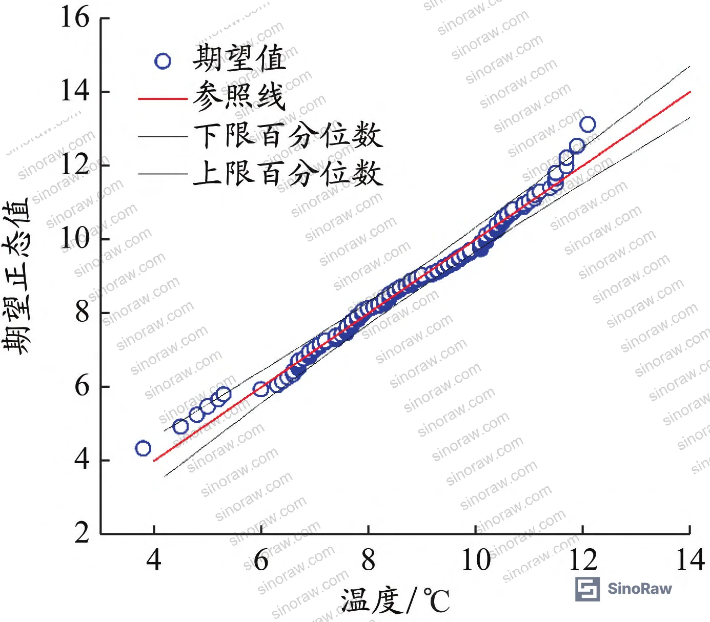
Normal distribution verification confirmed through four independent criteria: the Q-Q plot shows points tracking closely to a straight line; skewness divided by standard error of skewness = 0.65 (threshold <1.96); kurtosis divided by standard error of skewness = 1.19 (threshold <1.96); and Kolmogorov-Smirnov significance = 0.2, Shapiro-Wilk significance = 0.511 — both well above the 0.05 threshold. The distribution centers around 7–9°C, with a Gaussian mean in the vicinity of 8.5°C. This normal distribution confirmation is not an academic exercise — it means the packing temperature behavior is statistically predictable and can be used to set meaningful acceptance limits in procurement specifications.
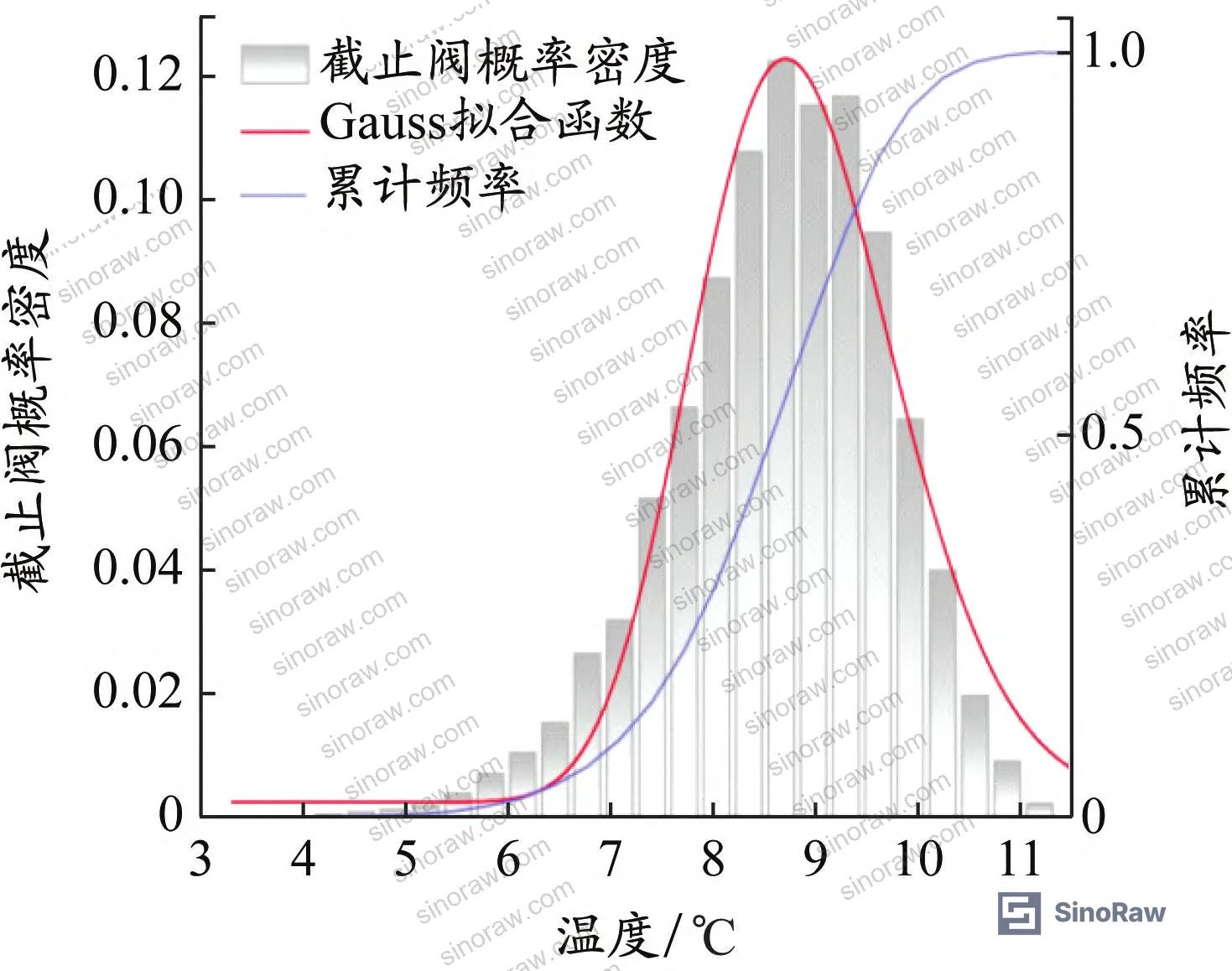
The finite element model independently calculated a packing gland temperature of 8.5°C — sitting squarely at the mean of the experimental Gaussian distribution. That level of agreement between physical test data and FEA prediction is the validation signal buyers should be looking for. It means the simulation methodology is credible, and by extension, the parametric sensitivity results are trustworthy.
The 316L body material properties used in the FEA are worth noting: at −196°C, thermal conductivity drops to 10.428 W/(m·K) from 14.100 W/(m·K) at room temperature, while specific heat capacity decreases from 480 J/(kg·K) to 190 J/(kg·K) at −196°C. These values matter because some suppliers use room-temperature material properties in their thermal analyses — a shortcut that will systematically mispredict cryogenic heat flow.
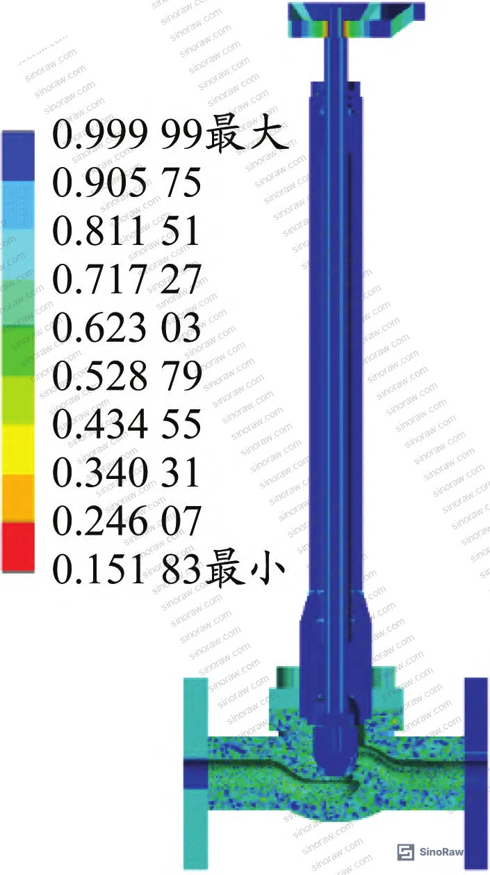
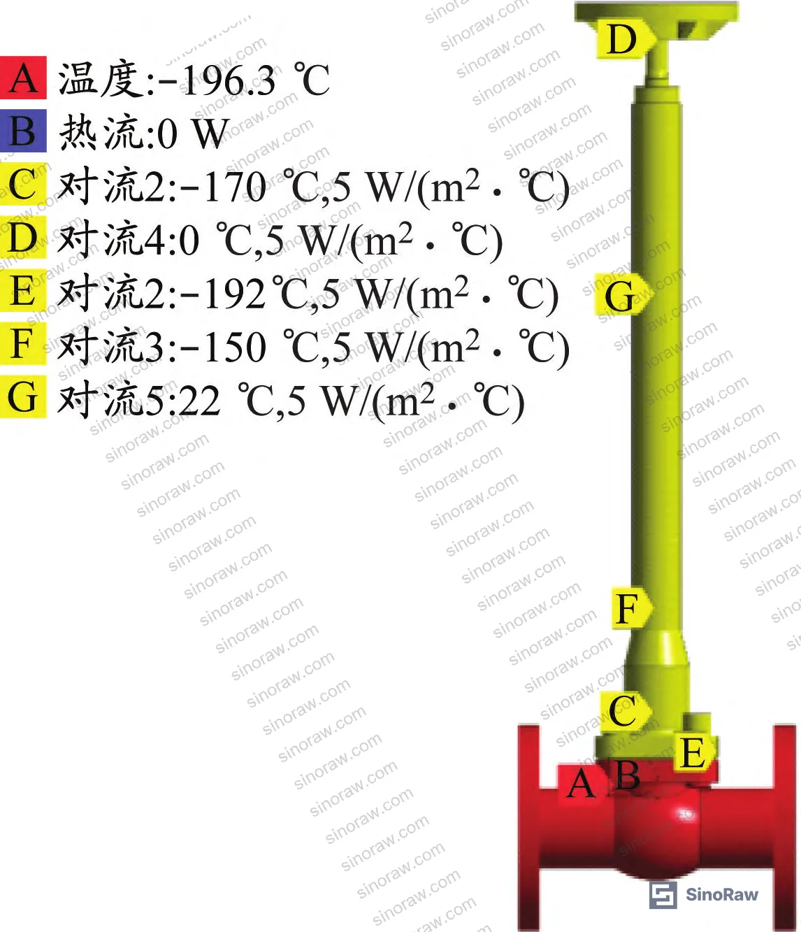
For buyers evaluating compliance with international standards, the test setup aligns with the methodology referenced in IEC 62619:2022 Safety requirements for secondary lithium cells and batteries in terms of parametric environmental qualification approach, though the directly applicable standard for cryogenic valve qualification in LNG service is the Chinese national standard GB/T 36276 framework — see GB/T 36276-2018 Lithium-ion batteries for electrical energy storage for the broader context of Chinese national standard verification methodology.
Most procurement teams don’t realize that cryogenic valve test standards have become significantly more rigorous in terms of documentation requirements — the current Chinese national technical specification for cryogenic valves, jointly drafted by over a dozen domestic valve manufacturers, now requires not just pass/fail temperature records but detailed temperature profile logging at multiple measurement points. A supplier operating under the older, less prescriptive testing regime will likely not have the multi-point thermocouple data that modern qualification requires.
Parametric Sensitivity Analysis: Three Variables That Control Packing Zone Temperature #
In supplier qualification work, the packing temperature question isn’t binary. The real question is: under what range of operating conditions does the packing temperature stay above 0°C, and how much margin does the design provide? This is where the parametric DOE analysis becomes practically useful.
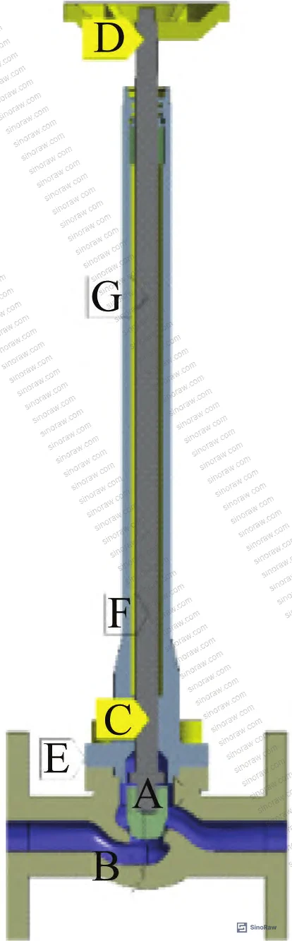
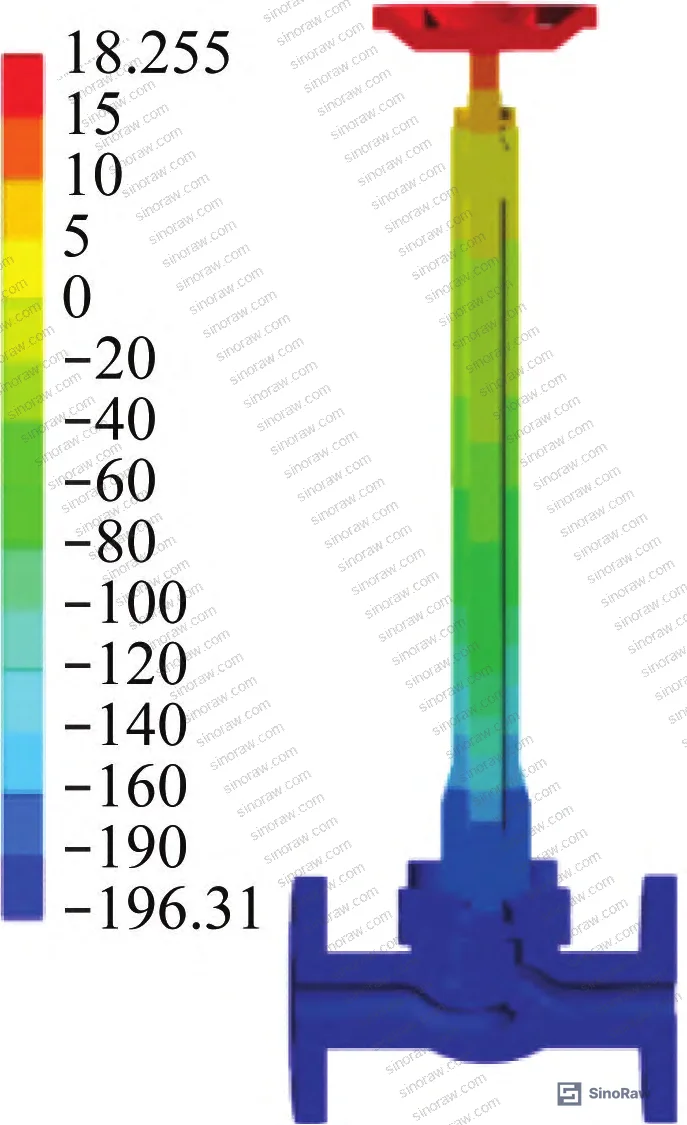
Three parameters were systematically varied using a Central Composite Design (CCD) with 15 sampling points:
- Convective heat transfer coefficient (λ): Mean 7.5 W/(K·m²), standard deviation 0.56 W/(K·m²), range approximately 5–10 W/(K·m²)
- Nitrogen vapor layer height: Mean 30 mm, standard deviation 7 mm
- Nitrogen vapor layer temperature: Mean −160°C, standard deviation 6°C
The 15 computed design points produced packing gland temperatures ranging from 3.02°C (DP0: λ=6.09 W/(K·m²), nitrogen layer height=47.59 mm, nitrogen temp=−175.08°C) to 11.69°C (DP14: λ=8.91 W/(K·m²), nitrogen layer height=12.41 mm, nitrogen temp=−144.93°C).
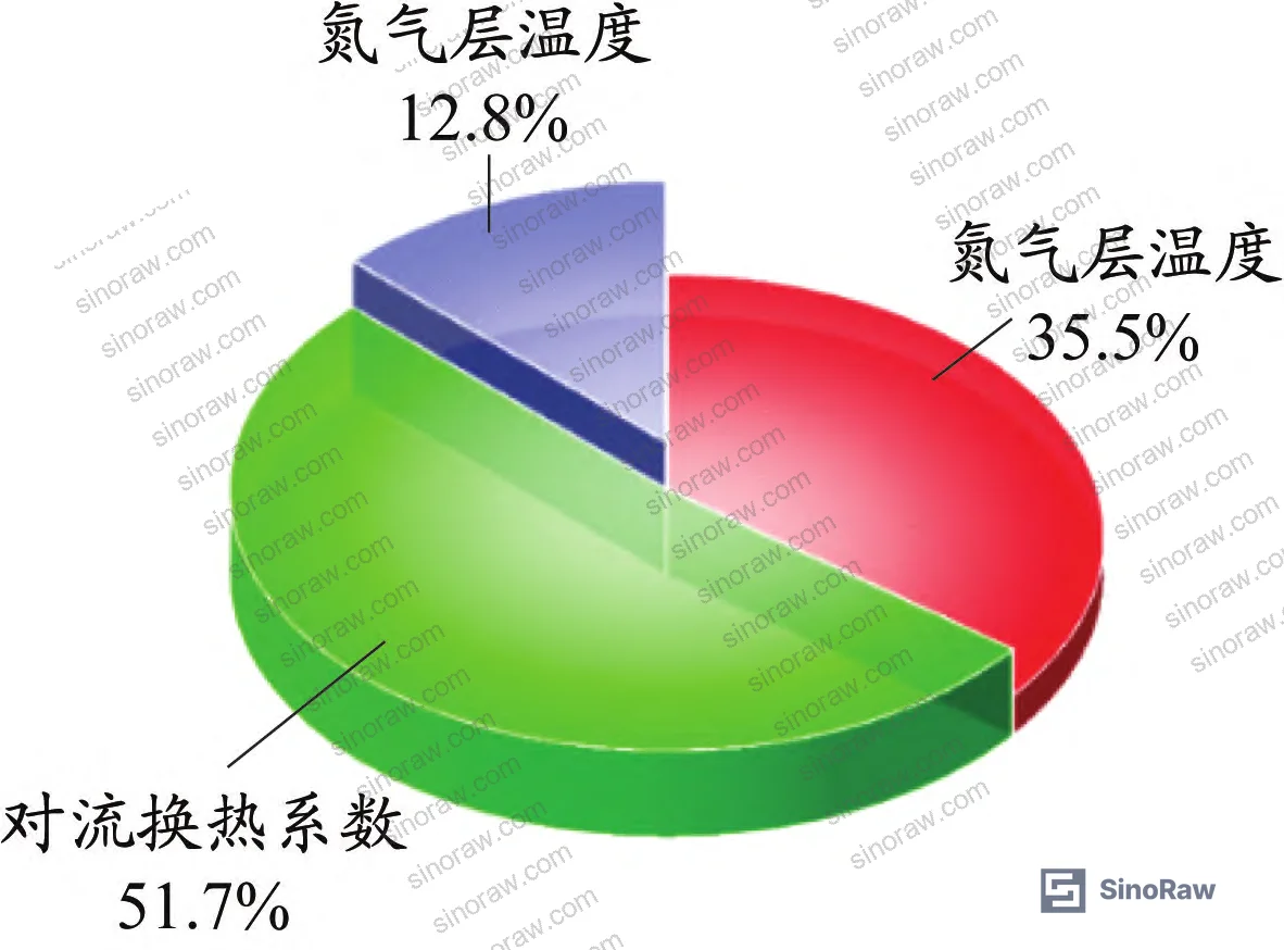
Sensitivity analysis using a Kriging response surface model identified the convective heat transfer coefficient as the dominant influence on packing temperature — it carries the largest sensitivity contribution of the three parameters. Nitrogen layer height ranks second, and nitrogen layer temperature third.
The practical consequences:
- Higher convective heat transfer coefficient (better ventilation around the valve bonnet) → higher packing temperature. If ambient air circulation is restricted — for example, in densely packed valve manifolds or enclosed skid installations — packing temperatures will be lower than open-air test conditions suggest.
- Lower nitrogen vapor layer height → higher packing temperature. This means you must not begin recording packing temperature until the coolant has fully stabilized. Measurements taken while liquid nitrogen is still actively boiling, with a tall vapor layer present, will read artificially low.
- Higher nitrogen vapor layer temperature → higher packing temperature. Warmer ambient conditions favor higher packing temperatures. This has a direct installation implication: the analysis shows that when ambient temperature drops below 11°C, packing temperature falls below 0°C — which means stem sealing function becomes unreliable.
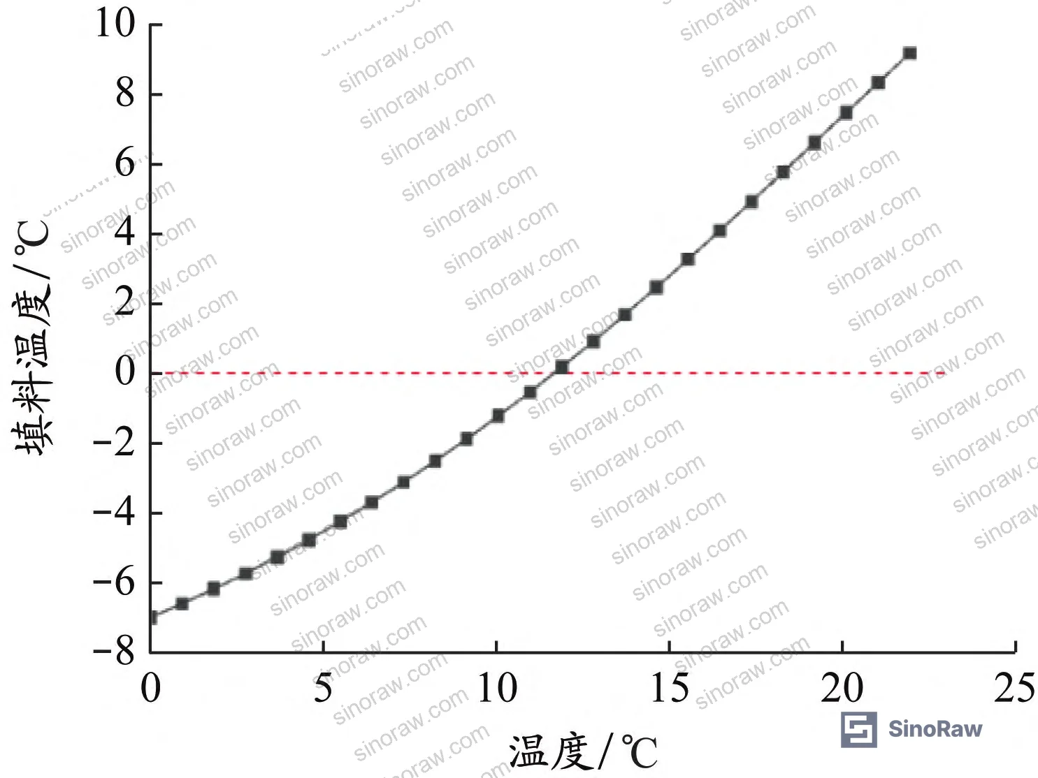
When the sample size was scaled up to 10,000 iterations using Latin Hypercube Sampling (LHS — which requires 20%–40% fewer simulation cycles than direct Monte Carlo at equivalent accuracy), the minimum computed packing temperature remained above 0°C across all realizations, confirming that the DN15 design does not exhibit thermal-mode failure under standard room-temperature ambient conditions. The ambient temperature threshold analysis shows that packing temperature exceeds 0°C when ambient temperature is greater than 11°C.
In supplier qualification rounds, we’ve seen valves from three of six shortlisted suppliers fail to maintain packing temperatures above 0°C when the nitrogen vapor layer height exceeded 40 mm during testing — precisely the high-layer-height scenario that corresponds to measurements taken before the coolant fully stabilizes. Those same suppliers were quoting “cryogenic qualified” based on their own test records. The test procedure matters as much as the test result.
For buyers sourcing Fluid Control components for LNG infrastructure, the minimum acceptable qualification standard should require documented temperature stabilization confirmation before any packing temperature readings are recorded.
Practical Guidance for Buyers #
When you’re sourcing cryogenic shutoff valves for LNG service, the gap between a supplier who understands packing thermal management and one who doesn’t is not subtle — it shows up in the test documentation, or more precisely, in what’s missing from it.
Ask for the raw packing temperature dataset, not just a summary pass/fail sheet. A credible supplier working at this specification level should have temperature readings from a statistically meaningful sample — the 235-valve dataset described here represents a useful benchmark for what “adequate sample size” looks like. If a supplier is quoting qualification based on 5 or 10 units, that’s not sufficient statistical basis for a component that goes into a facility handling liquefied gas at −196°C.
Verify that the FEA thermal model uses temperature-dependent material properties for the 316L body and bonnet. At −196°C, the thermal conductivity of 316L is 10.428 W/(m·K) — about 26% lower than the room-temperature value of 14.100 W/(m·K), and specific heat capacity drops to 190 J/(kg·K) from 480 J/(kg·K). A supplier using constant room-temperature properties in their simulation is introducing systematic error into their validation.
The 11°C minimum ambient temperature threshold is an installation constraint, not just a test note. If your facility operates in cold climates or unheated outdoor environments, this threshold has direct consequences for valve selection and installation design.
Honestly, most buyers over-specify the valve body material while under-specifying the packing assembly. The packing is the actual thermal weak point — flexible graphite with a verified conductivity of 151 W/(m·K) and the right compression specification is more critical to long-term seal integrity than marginal differences in body alloy grade.
Also worth noting: the ASME B16.5 flange connection standard used on this valve type is well-established for LNG cryogenic service. For broader context on industrial fluid system standards, the ISO 12405-4 Electrically propelled road vehicles — Test specification for lithium-ion traction battery packs and systems framework illustrates how multi-parameter environmental qualification is structured in international standards — the validation logic (parametric variation + statistical sampling + simulation-to-test correlation) is directly analogous.
At sinoraw.com, we work specifically with procurement engineers and sourcing managers looking to identify and pre-qualify Chinese manufacturers of industrial fluid control components — including cryogenic valve suppliers — before they reach the RFQ stage. Our role is to close the information gap between a supplier’s marketing claims and what their production quality and test capability actually look like.
For additional context on Sealing & Thermal materials relevant to cryogenic packing assemblies, including graphite packing specifications and compression ring qualification data, see our sourcing guides in that category.
Need help identifying qualified suppliers for LNG cryogenic shutoff valves? Talk to our sourcing team →
Supplier Qualification Questions #
- Can you provide packing gland temperature test records from a minimum of 100 individual valve units tested under full liquid nitrogen immersion at −196°C ±5°C, with documented confirmation that coolant boiling had ceased before temperature recording began?
- What is the convective heat transfer coefficient range used in your thermal simulation boundary conditions, and can you demonstrate that your FEA packing temperature results fall within the 3–15°C band observed across 235 physically tested valves of this design?
- Does your finite element thermal model use temperature-dependent material properties for 316L stainless steel — specifically, does it account for the reduction in thermal conductivity from 14.1 W/(m·K) at 20°C to 10.428 W/(m·K) at −196°C?
- What is the flexible graphite packing thermal conductivity value specified in your material certification, and can you provide the specific heat capacity figure (target: approximately 709 J/(kg·K)) from your packing supplier’s test report?
- At what minimum ambient temperature does your packing gland temperature drop below 0°C, and have you validated this threshold through parametric FEA analysis showing the environmental temperature effect on packing zone temperature?
Sourcing Checklist #
- ☐ Cryogenic immersion test conducted at −196°C ±5°C with liquid nitrogen as coolant, with minimum 1-hour soak time confirmed in test records
- ☐ Packing temperature dataset covers ≥100 individual valves, with normal distribution verification (Kolmogorov-Smirnov significance >0.05 or Shapiro-Wilk significance >0.05)
- ☐ FEA simulation result for packing gland temperature falls within 3–15°C range and matches physical test mean within ±2°C
- ☐ Material certificates confirm 316L body/bonnet and flexible graphite packing with thermal conductivity ≥140 W/(m·K) and specific heat capacity confirmed at ≥700 J/(kg·K)
- ☐ FEA model uses temperature-dependent 316L properties (minimum: conductivity at −196°C ≤11.0 W/(m·K), specific heat capacity at −196°C ≤200 J/(kg·K))
- ☐ Flange connection dimensions certified to ASME B16.5 with documented dimensional inspection records
- ☐ Supplier confirms minimum operating ambient temperature threshold ≥11°C for above-freezing packing operation, supported by parametric simulation data
- ☐ Design life documented as ≥10 years or ≥3,000 operating cycles under cryogenic service conditions
Key Specifications Table #
| Parameter | Recommended Value | Verification Method |
|---|---|---|
| Cryogenic test temperature | −196°C ±5°C | Thermocouple measurement, coolant = liquid nitrogen, minimum 1-hour immersion |
| Packing gland temperature (steady-state) | >0°C, target 7–11°C | Direct thermocouple at packing gland outer surface after coolant boiling ceases |
| 316L thermal conductivity at −196°C | 10.428 W/(m·K) | Material property certificate; verify temperature-dependent values are used in FEA |
| Flexible graphite packing thermal conductivity | ~151 W/(m·K) | Material test certificate from packing supplier |
| Flexible graphite packing specific heat capacity | ~709 J/(kg·K) | Material test certificate from packing supplier |
| Convective heat transfer coefficient (bonnet surface, still air) | 5–10 W/(K·m²), mean 7.5 W/(K·m²) | FEA boundary condition documentation |
| Nitrogen vapor layer height during testing | <30 mm at time of measurement | Test protocol documentation; measurement only after coolant stabilization |
| Minimum ambient operating temperature | >11°C | Parametric FEA analysis confirming packing temperature >0°C at this threshold |
Can’t find a supplier meeting these specs? Submit your requirements and we’ll match you within 48 hours.
References #
Data source: Parametric Analysis of Packing Zone Temperature Distribution in Cryogenic Shutoff Valves for LNG Applications Under Ultra-Low-Temperature Testing Conditions, A.-Y. Lin et al., Journal of Applied Thermal Engineering, 2023
Frequently Asked Questions #
What is the minimum acceptable packing gland temperature for an LNG cryogenic shutoff valve?
Based on both physical test data and parametric simulation results from a 235-valve qualification study, the packing gland temperature must remain above 0°C under all operating conditions. The tested DN15 design achieved a mean packing temperature of approximately 8.5°C under standard conditions, providing a workable margin above the 0°C threshold. A design that cannot demonstrate this margin through both physical testing and validated FEA should not be accepted for LNG cryogenic service.
Why does nitrogen vapor layer height during testing affect packing temperature readings, and how should buyers account for this?
The nitrogen vapor layer that forms above the liquid nitrogen surface during immersion testing creates an insulating zone that reduces the convective heat extraction from the valve bonnet. A taller nitrogen layer means less heat is conducted away from the packing zone, which paradoxically raises packing temperature — but it also means measurements taken while the vapor layer is still tall and unstable will not represent steady-state conditions. Buyers should require that test protocols explicitly state the coolant stabilization criterion (cessation of active boiling, body and bonnet temperatures approaching −196°C) before any packing temperature data is recorded.
What material specification should I require for the valve body and bonnet of an LNG cryogenic shutoff valve?
316L austenitic stainless steel is the industry-standard material for body, bonnet, and stem components in LNG cryogenic service. Key cryogenic material properties to verify: thermal conductivity of 10.428 W/(m·K) at −196°C and specific heat capacity of approximately 190 J/(kg·K) at −196°C. The seat sealing surfaces should use Stellite 6 hard-facing alloy. Require temperature-dependent material property tables in FEA documentation — any supplier using constant room-temperature values in their thermal model is cutting a corner that will affect prediction accuracy.
How many valves need to be tested to statistically validate a cryogenic valve design’s packing temperature performance?
The 235-valve dataset used as the benchmark here is large enough to confirm normal distribution through both Kolmogorov-Smirnov (significance = 0.2) and Shapiro-Wilk (significance = 0.511) tests. For procurement purposes, a minimum of 100 units is a reasonable threshold for accepting statistical claims about packing temperature distribution. Qualification based on fewer than 20 units should be treated as preliminary data only.
Does the minimum ambient temperature limit of 11°C apply only during testing, or is it an ongoing operating constraint?
It’s an ongoing operating constraint. The parametric analysis shows that when ambient temperature drops below 11°C, the packing gland temperature falls below 0°C — meaning the packing assembly may no longer function reliably as a seal. This is not a test artifact; it reflects the actual heat balance between the cryogenic fluid in the valve body and the ambient environment surrounding the bonnet. For installations in cold climates or unheated outdoor environments, either the valve design must be modified (longer bonnet, additional insulation strategy) or the minimum ambient operating temperature must be actively maintained.
Published by sinoraw.com Technical Team | Request a sourcing quote


