

TL;DR #
Sealing surface dimensional accuracy after grinding on Y-type globe valves can reach 0.001–0.003 mm when proper 6-axis fixturing is applied, but traditional spot-weld clamping methods routinely fail to provide sufficient eccentric stability, causing workpiece shift and surface finish rejection. For buyers specifying high-pressure Y-type globe valves, the supplier’s grinding fixture design is a direct proxy for sealing quality — ask for it before accepting any first article. Require documentation of clamping method, dimensional tolerance achieved post-grind, and confirmation that the fixture accommodates your specific valve body geometry.
Overview #
Most procurement teams treat Y-type globe valve sealing surface finish as a black-box outcome — you specify Ra roughness or leakage class, and assume the supplier’s shop floor delivers it. That assumption is expensive when it fails. Engineering data from a precision valve manufacturer’s tooling development program — covering multiple valve body sizes and a purpose-built grinding fixture qualification — reveals exactly where conventional methods break down and what a well-designed fixture must accomplish.
The Y-type globe valve’s defining feature is its 45° flow channel angle, which aligns the flow path into a straight-line trajectory. Compared to a conventional S-shaped globe valve flow path, this geometry significantly reduces flow resistance and lessens fluid impingement erosion on the disc, extending service life in demanding applications. That same 45° body geometry is precisely what makes sealing surface grinding difficult: the valve body is geometrically irregular, its center of mass is offset, and standard symmetric clamping fixtures simply cannot provide stable eccentric restraint.
For procurement engineers sourcing from Chinese manufacturers, understanding the fixture engineering behind sealing surface finishing matters more than most buyers realize. At sinoraw.com, our sourcing specialists work directly with Guangzhou-based and regional Chinese valve manufacturers across industrial fluid control categories — the analysis here is drawn from hands-on supplier evaluation, not from catalog reading.
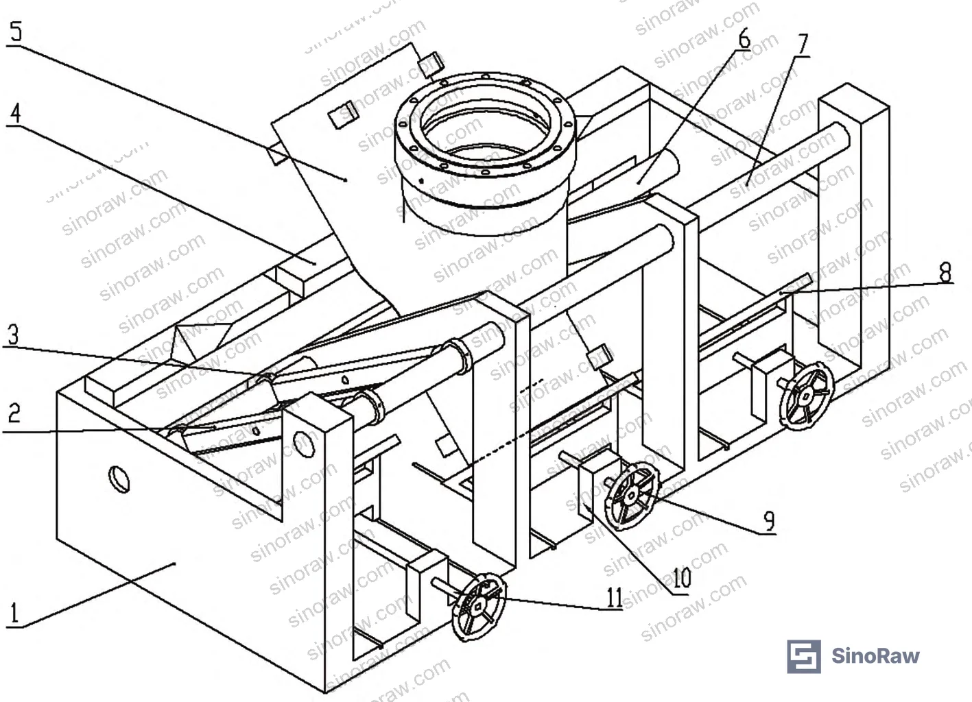
Y-Type Globe Valve Grinding: Why the 45° Geometry Creates a Fixturing Problem #
The core challenge is geometric. A Y-type globe valve body presents three functional ports — inlet, outlet, and the central sealing bore — arranged in a Y configuration, with the sealing axis at 45° to the main flow axis. When you need to grind the sealing surface, that surface must be presented vertically to the grinding tool. That means the valve body sits at an angle on the fixture, with its center of mass eccentric to any natural clamping axis.
Traditional shop-floor workarounds involved tack-welding temporary support points onto the valve body exterior, then using those points as improvised fixture contacts. This is the approach that consistently underperforms. In supplier qualification evaluations, we observed that this spot-weld method produces two failure modes: first, clamping eccentricity that allows micro-rotation during grinding, immediately degrading the sealing surface geometry; second, inadequate holding force that permits workpiece shift mid-cycle, requiring restart or — more commonly — shipping a marginally out-of-spec part that won’t be caught until final leak testing.
The dimensional tolerance requirement for a ground sealing surface is tight: post-grind dimensional accuracy must fall within 0.001–0.003 mm. That’s a 1–3 micron band. You cannot achieve that consistently with a clamping setup that relies on tack-welds and operator judgment about “sufficient” stability.
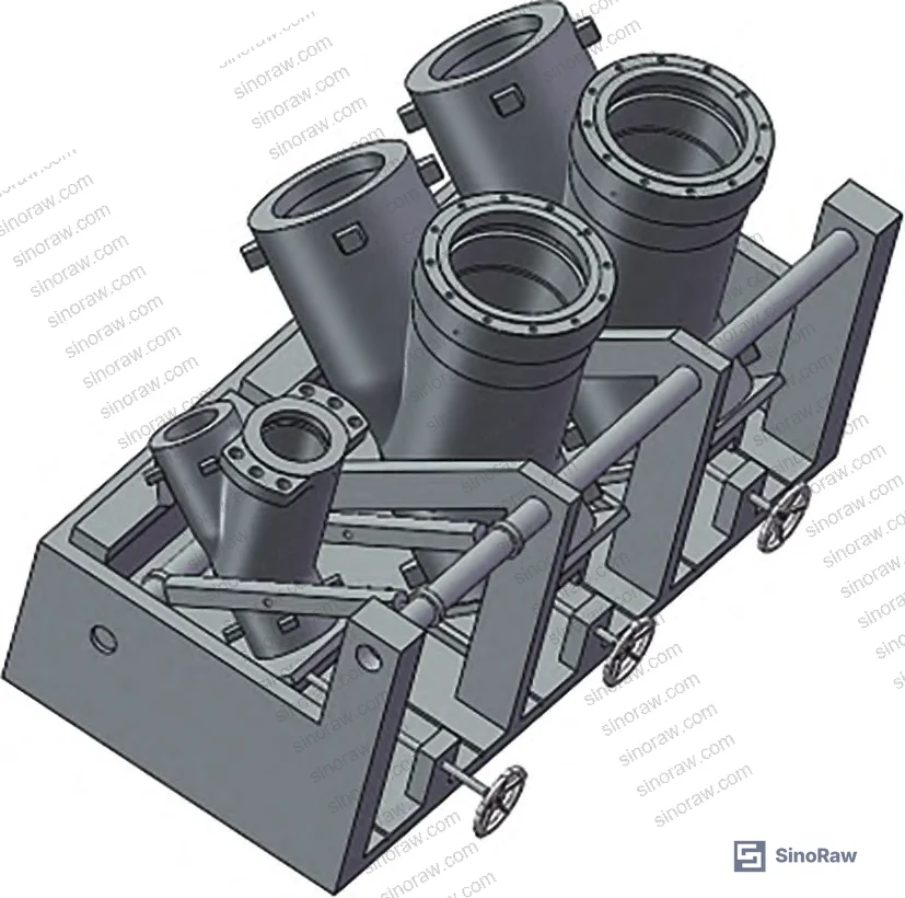
The engineering solution documented here uses a sliding support plate with a matched 45° inclined surface — aligned to the valve’s own 45° flow channel angle — combined with V-groove beam support for the body’s curved sidewalls. This creates what is effectively a 6-axis constraint: front-to-back and vertical displacement are eliminated by the sliding plate lock, while lateral displacement is controlled by the pull-ring and valve body fixing plate assembly. The result is full 6-face spatial fixturing of the valve body before grinding begins.
Comparison: Clamping Method Performance
| Clamping Method | Eccentric Stability | Multi-Size Compatibility | Setup Time |
|---|---|---|---|
| Traditional spot-weld temporary support | Insufficient — prone to micro-rotation | Single size per setup | Long — requires weld/removal per valve |
| Symmetric standard fixture | Inadequate for 45° offset body | Limited | Medium |
| 45° sliding plate + V-groove beam (6-axis) | High — 6-face spatial constraint | Multiple sizes, single fixture | Short — handwheel adjustment only |
Honestly, most buyers over-specify sealing surface Ra without ever asking how the supplier achieves it. A supplier quoting Ra 0.4 or leakage Class VI with no coherent answer about their grinding fixture methodology should raise an immediate red flag in your qualification audit.
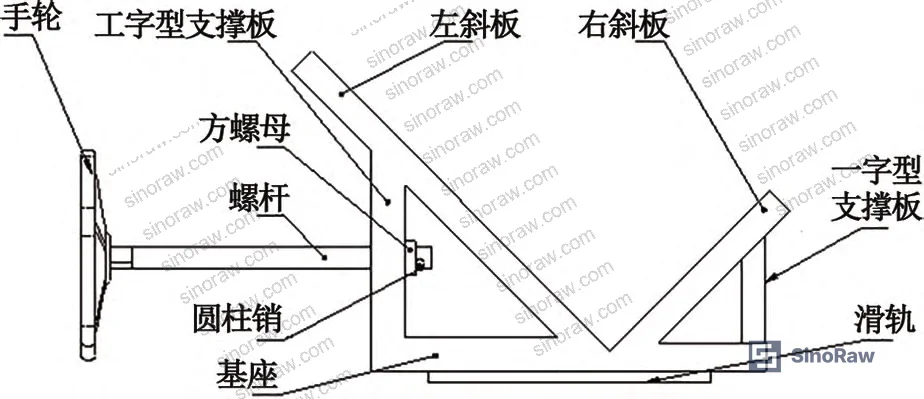
Key Fixture Components and Engineering Design Criteria #
Understanding the fixture’s structural logic helps buyers write better acceptance criteria and ask sharper qualification questions.
The Sliding Support Plate (45° Inclined)
The sliding support plate is the dimensional adapter between the fixture and the valve body. Its two inclined faces are set at 90° to each other — forming a symmetric V-geometry when viewed from above — while the entire plate surface is inclined at 45° relative to the frame base. This 45° matches the valve body’s flow channel inclination angle exactly. Drive is through a handwheel-leadscrew-square nut mechanical chain: rotating the handwheel translates the plate along guide rails in the frame base, positioning the support for different valve body sizes. A cylindrical pin locks the leadscrew against axial ejection. This mechanism converts rotary motion to linear slide — no power tools, no special skills required for adjustment.
The V-Groove Beam (T-Mortise Construction)
The V-groove beam is a structurally complex component that cannot be machined in a single operation. Its cross-section is hybrid: lower half is semicircular (for rotational adjustment in the frame’s semicircular slots), upper half is rectangular with V-groove features cut into it. These two halves are manufactured separately and joined via T-shaped mortise-and-tenon (榫卯) joinery — a traditional Chinese woodworking principle applied here in precision metal fabrication. Tight dimensional tolerances in the tenon joint ensure the assembled beam behaves as a monolithic component.
The semicircular lower profile enables rotational fine-adjustment: by rotating the beam within its seat, the V-groove contact face can be optimized to match any specific valve body sidewall radius. This means a single V-groove beam can accommodate multiple valve body sizes without replacement — the rotation compensates for radius variation. Different V-groove widths are also cut into the beam’s upper face, with spacing adjusted to match actual valve body widths for different size classes.
The Pull-Ring and Valve Body Fixing Plate Assembly
The pull-ring (固定板拉环) is circular, with a threaded post on one face and a locking threaded hole on the other. Left-hand and right-hand thread combinations on the two posts create opposing tension when tightened — a classic anti-loosening mechanical design that generates mutual clamping force rather than relying on friction alone. The assembly slides along the pull-ring beams (two parallel beams running front-to-back through the frame), and set screws lock position once the fixing plate is positioned against the valve body. Fine-thread set screws on the fixing plate itself provide final contact adjustment against irregular exterior valve body surfaces, preventing micro-movement from small-area contact points.
The L-Frame
The frame is an L-bed configuration with triangular reinforcing ribs. Two pull-ring beams pass through frame through-holes and rib holes — one at the front-bottom, one at the rear-top — creating parallel spatial tracks at different heights. This offset parallel arrangement is intentional: it creates geometrically independent work zones that do not interfere with each other, allowing multiple valve bodies of different sizes to be clamped and ground simultaneously without cross-interference.
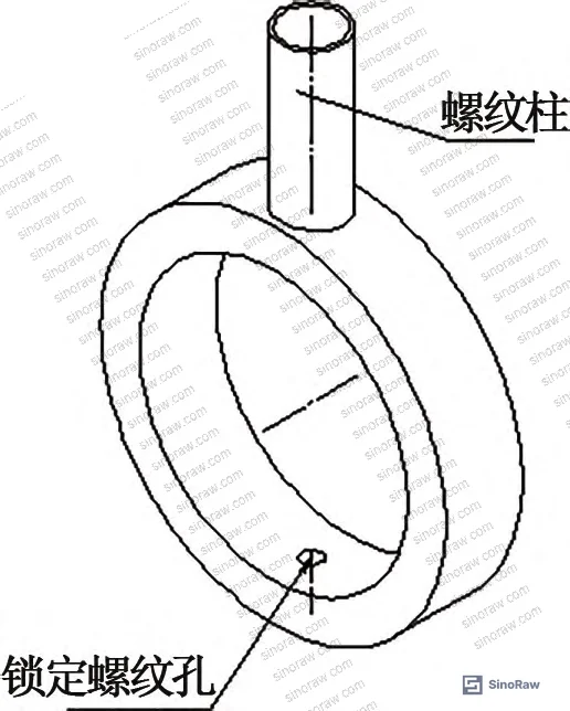
Sealing Surface Grinding Process and Clamping Sequence #
The clamping sequence matters. Operator error during loading is one of the leading causes of sealing surface rework in medium-volume valve production shops.
The correct procedure: the operator first turns the handwheel to position the sliding support plate for the valve body size being loaded. The valve inlet port is placed onto the 45° sliding plate face. The outlet port exterior wall is seated into the V-groove beam. Then the pull-ring and valve body fixing plate assembly is slid along the pull-ring beams to contact the valve body — adjusted for the specific body dimensions — and locked with set screws. The fixing plate’s own set screws are tightened against the valve body exterior for final micro-contact adjustment. After complete clamping, the sealing surface (at the central bore) is presented in a vertical orientation — correct for grinding tool approach.
This sequence achieves the 6-face spatial constraint: front/rear fixed by the sliding plate lock; up/down constrained by the V-groove and sliding plate contact surfaces; left/right constrained by the pull-ring beam and fixing plate assembly.
The grinding process itself combines mechanical abrasion with chemical action. The abrasive compound (磨料 + 研磨液) serves dual functions: the liquid component dilutes the abrasive and cools/lubricates the workpiece, while oil-based components in the liquid form a surface oxide film that accelerates material removal. The grinding tool conforms to the sealing ring surface and executes compound motion along that mating surface. When clamping stability is maintained throughout, the result is dimensional accuracy within 0.001–0.003 mm and significant surface roughness reduction on the sealing face.
Most procurement teams don’t realize that the grinding fixture design is rarely documented in valve manufacturer quality plans — ISO 9001 certification tells you a quality system exists, but says nothing about whether the fixture can actually hold a 45° offset valve body stable to ±1 micron during grinding. Ask for fixture drawings or at minimum a written description of the clamping method during supplier qualification.
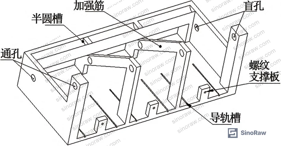
For high-pressure valve specifications, the grinding quality directly determines sealing performance against IEC 62619:2022 Safety requirements for secondary lithium cells and batteries — not a directly applicable standard here, but the principle of documented process control over sealing-critical surfaces is identical across precision fluid control components. For valve assembly in process plant applications, refer to ISO 12405-4 Electrically propelled road vehicles — Test specification for lithium-ion traction battery packs and systems for test methodology parallels in precision component qualification. For broader industrial component quality frameworks, IEC 61960-3 Secondary lithium cells and batteries for portable applications provides reference for systematic component-level qualification documentation requirements that translate directly to valve procurement practice.
Practical Guidance for Buyers #
If you are procuring Y-type globe valves for high-pressure service, the sealing surface finish specification you write into the purchase order is only as good as your supplier’s ability to deliver it — and that depends almost entirely on their grinding fixture capability.
Three practical points from qualification experience:
First, ask for grinding fixture documentation during supplier audit. You don’t need engineering drawings (though that’s ideal). At minimum, ask the supplier to describe how they clamp Y-type valve bodies during sealing surface grinding. A supplier who cannot explain their fixture methodology is likely still using improvised spot-weld supports — acceptable for commodity valves, not acceptable for tight-tolerance high-pressure applications.
Second, specify the post-grind dimensional tolerance explicitly: sealing surface dimensional accuracy ≤0.003 mm, with verification by CMM or precision gauge, documented in the first article inspection report. Do not accept surface roughness Ra as the only acceptance criterion — Ra tells you about surface texture, not dimensional accuracy of the sealing geometry.
Third, if the supplier is running multiple valve sizes through the same production line, ask whether their grinding fixture is size-adjustable or requires fixture changeover. Fixtures that require complete re-setup for each size class introduce setup error risk that a properly designed sliding-plate fixture eliminates.
At sinoraw.com, our sourcing team connects overseas procurement engineers with verified Chinese manufacturers of precision fluid control components — from high-pressure globe valves to Fluid Control and Sealing & Thermal products — and we evaluate supplier process capability, not just catalog specifications, before recommending any supplier for critical applications.
Need help identifying qualified suppliers for Y-type globe valves with documented sealing surface grinding capability? Talk to our sourcing team →
Supplier Qualification Questions #
- What is your post-grind dimensional accuracy specification for the sealing surface, and can you provide inspection records showing results consistently within the 0.001–0.003 mm tolerance band?
- Describe your clamping method for Y-type globe valve bodies during sealing surface grinding — specifically, how do you achieve eccentric stability for the 45° offset body geometry, and does your fixture provide constraint in all 6 spatial directions?
- Does your grinding fixture use a sliding support plate matched to the 45° valve body inclination angle, or do you rely on temporary support points or improvised fixturing for each body size?
- How do you adjust the V-groove beam contact geometry for different valve body sidewall radii — is the beam rotationally adjustable in its mount, and what is the range of body sizes your current fixture accommodates without beam replacement?
- What anti-loosening mechanism do you use on the valve body fixing plate assembly, and can you confirm that your set-screw locking system prevents micro-movement of the valve body against the fixing plate during grinding motion?
Sourcing Checklist #
- ☐ Supplier can document post-grind sealing surface dimensional accuracy ≤0.003 mm with CMM or precision gauge measurement records from production batches
- ☐ Grinding fixture provides 6-face spatial constraint (front/rear, up/down, left/right) for Y-type valve bodies with 45° flow channel geometry
- ☐ Fixture uses a 45° inclined sliding support plate adjustable by leadscrew/handwheel mechanism — not improvised tack-weld or spot-weld temporary supports
- ☐ V-groove beam is rotationally adjustable within its semicircular seat to optimize contact against different valve body sidewall radii
- ☐ Valve body fixing plate assembly uses opposing thread (left-hand + right-hand) anti-loosening mechanism on pull-ring threaded posts
- ☐ Fixture can accommodate at least 3 different valve body size classes without complete fixture replacement, using adjustable V-groove widths and sliding plate repositioning
- ☐ First article inspection report includes both surface roughness (Ra) and dimensional accuracy measurements of the sealing surface — not Ra alone
- ☐ Supplier quality plan documents the clamping sequence and set-screw locking procedure for sealing surface grinding operations
Key Specifications Table #
| Parameter | Recommended Value | Verification Method |
|---|---|---|
| Sealing surface dimensional accuracy post-grind | 0.001–0.003 mm | CMM measurement or precision gauge, documented in first article inspection report |
| Sliding support plate inclination angle | 45° (matched to valve body flow channel angle) | Fixture drawing review + angle verification with precision inclinometer |
| Symmetric inclined plate included angle (V-geometry) | 90° | Fixture drawing review + CMM verification of plate geometry |
| V-groove beam lower section geometry | Semicircular profile enabling rotational adjustment in frame slots | Physical inspection of beam cross-section + rotation test in frame seat |
| Anti-loosening mechanism on fixing plate assembly | Opposing left-hand/right-hand thread combination on pull-ring posts | Thread direction verification during fixture audit |
| Frame structure | L-bed with triangular reinforcing ribs, dual pull-ring beams at offset parallel positions | Structural drawing review + physical audit of rib attachment and beam routing |
Can’t find a supplier meeting these specs? Submit your requirements and we’ll match you within 48 hours.
References #
Data source: Fixture Design for Sealing Surface Grinding of Y-Type Globe Valves with Multi-Size Adaptive Clamping, J.-E. Chen et al., Journal of Mechanical Engineering and Automation, 2024
Frequently Asked Questions #
Why is the 45° angle so critical in Y-type globe valve grinding fixture design?
The Y-type globe valve body has its sealing bore oriented at 45° to the main flow axis — a design feature that reduces flow resistance compared to conventional S-path globe valves. This same geometry means the valve body sits in an eccentrically offset position on any conventional fixture, creating an imbalanced load during grinding. The fixture’s 45° sliding plate matches this angle exactly, bringing the sealing surface into a vertical orientation for grinding while distributing clamping forces symmetrically around the offset center of mass. Without this match, even a well-executed clamping operation will have residual eccentric moment that manifests as micro-rotation or shift during the grinding cycle.
What does “6-face spatial constraint” mean in practical terms for valve body clamping?
It means the valve body is physically prevented from moving in all three translational axes — fore/aft, up/down, and left/right. Front-to-back and vertical displacement are blocked by the locked sliding plate; the V-groove beam and sliding plate surfaces handle vertical constraint; the pull-ring beam and valve body fixing plate assembly handles lateral constraint. The result is that the valve body cannot translate or rotate during grinding regardless of the forces applied by the grinding tool and abrasive compound. This is the condition required to maintain dimensional accuracy within the 0.001–0.003 mm tolerance band.
Can this fixture design handle both small and large Y-type globe valves?
Yes, multi-size accommodation is a primary design objective. The sliding support plate adjusts position along guide rails to suit different body lengths. The V-groove beam upper face has multiple V-groove widths cut at different spacings to match different body widths. The V-groove beam itself rotates in its semicircular frame seat to optimize contact against different body sidewall radii. The pull-ring and fixing plate assembly slides along the full length of the pull-ring beams to accommodate different body positions. The parallel dual-beam structure also allows multiple valve bodies — even of different sizes — to be clamped simultaneously in independent work zones.
What failure mode occurs most often when grinding fixtures are inadequate?
The primary failure is eccentric instability during the grinding cycle — the valve body micro-rotates or translates slightly as the grinding tool applies force and the abrasive compound creates chemical-mechanical interaction at the sealing surface. This produces a sealing surface that fails dimensional accuracy requirements (outside the 0.001–0.003 mm band) or has non-uniform surface finish. In production environments using traditional tack-weld temporary supports, this failure is often not caught until final leak testing, at which point rework or scrap is the only option. It is a costly failure mode that is entirely preventable with a properly designed fixture.
Is the V-groove beam’s T-mortise construction a quality concern or a feature?
It is a feature, though it requires tight manufacturing tolerance to work correctly. The V-groove beam’s cross-section — semicircular lower half, rectangular upper half with V-grooves — cannot be machined in a single setup on conventional equipment. Manufacturing the two halves separately and joining them via T-shaped mortise-and-tenon joinery is the established solution. The joint must be made to tight tolerances so the assembled beam behaves as a monolithic component. When evaluating suppliers, ask whether their V-groove beams are inspected as assemblies after joining — a beam with a loose mortise joint will introduce positional error directly into the valve body seating, defeating the purpose of the precision fixture.
Published by sinoraw.com Technical Team | Request a sourcing quote


