

TL;DR #
Forged ASME A350 LF2 CL1 valve bodies that pass chemical composition and hardness requirements can still carry pre-existing folding defects from billet forging — defects that penetrate up to 30 mm deep and only propagate into service-ending cracks once assembly constraint stress is applied. For buyers procuring Class 900 / PN150 welded flange globe valves for oil and gas station service, passing material certificates alone are insufficient quality evidence. Require 100% inner and outer surface NDE on every valve body before acceptance.
Overview #
When a batch of welded flange globe valves at an oilfield station was found cracked during installation — not after years of service, but on day one — the incident exposed a quality gap that material certificates simply cannot close. Independent metallurgical investigation at a national-level tubular goods research institute examined multiple failed valve bodies using penetrant testing, chemical spectroscopy (ARL4460 OES), Brinell hardness testing, laser confocal metallographic observation per GB/T 226, SEM morphology (VEGA II), and EDS analysis (INCA 360) to characterize both macro and micro crack features across six discrete crack locations in a single valve body.
The valves in question are primary instrument valves — welded directly to process lines in refinery and oilfield station piping systems. Their weld ends measured 19.05 mm (3/4 in) and 12.07 mm (1/2 in), the flange rating was Class 900 / PN150, and the valve body was integrally forged to a one-piece construction with integrated saddle-type weld nozzles. Internal fittings were 316 stainless steel; sealing packing was flexible graphite. This is not an exotic or unusual valve — it’s the type of hardware procured by the tens of thousands for upstream and midstream oil and gas infrastructure.
The metallurgical verdict was unambiguous: chemistry and hardness both met specification. The failure root cause had nothing to do with material grade. It was entirely a manufacturing process problem — one that 100% surface NDE at the factory would have caught before shipment.
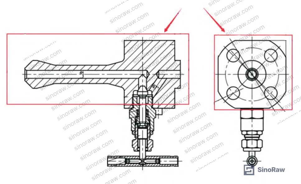
Crack Morphology and Folding Defect Mechanism in Forged Valve Bodies #
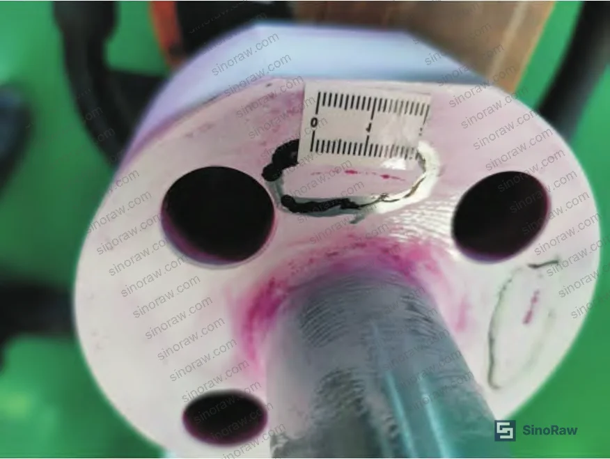
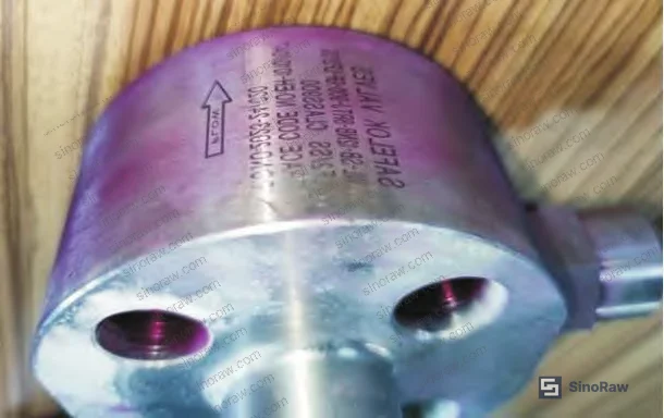
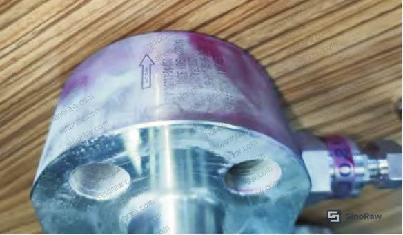
Six cracks were identified and measured on a single valve body, all concentrated on the weld side of the flange. Five were circumferential; one was radial on the handle side. Crack lengths ranged from 8.6 mm up to 25 mm. The full measurement dataset:
| Crack ID | Location | Orientation | Length |
|---|---|---|---|
| Crack 1 | Flange weld side | Circumferential | ~15 mm |
| Crack 2 | Flange weld side | Circumferential | ~20 mm |
| Crack 3 | Flange weld side | Circumferential | ~25 mm |
| Crack 4 | Flange weld side | Circumferential | ~25 mm |
| Crack 5 | Flange handle side | Radial | ~8.6 mm |
| Crack 6 | Flange weld side | Circumferential | ~17.5 mm |
When one linear indication was ground down 30 mm in depth and re-tested with penetrant, the indication remained clearly visible — meaning these are not shallow surface marks or machining artifacts. They are structural defects with real depth.
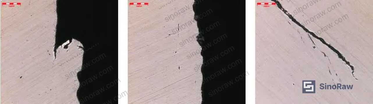
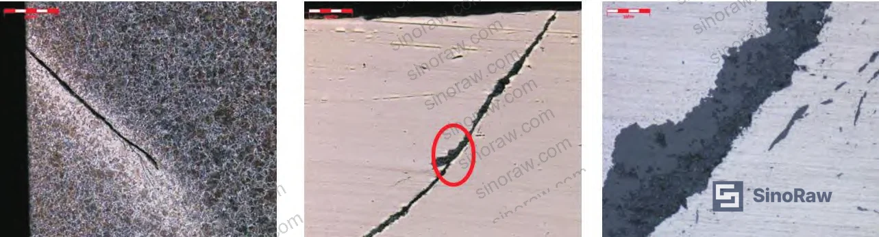
Metallographic cross-sections (etched in 2% nital) revealed the crack mechanism with precision. Sample 1: primary crack measured 1.66 mm in length along the section, 1.22 mm deep through the flange wall thickness. Sample 2: crack length 1.61 mm, depth 1.17 mm. Both cracks originated at the surface and propagated inward at a defined angle. Critically, the crack tips were blunt and rounded — not sharp stress-concentration fracture tips. Secondary micro-cracks were densely distributed along the edges. Significant decarburization was observed in the base metal adjacent to both cracks, on both sides and at the tips.
This combination — blunt crack tips, decarburization zone, dispersed slag inclusions of variable size embedded in the crack walls, iron oxide particles distributed along grain boundaries — is the diagnostic fingerprint of a folding defect. Folding occurs during hot forging when surface oxide scale or surface irregularities on the billet are folded inward rather than being expelled. The folded interface, now embedded in the forging, carries entrapped oxides (confirmed by EDS: primarily O, Fe, Zn) and a decarburized halo from the original hot-forming thermal exposure.
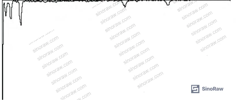
EDS analysis of crack-filling material confirmed the elemental composition: oxygen, iron, and zinc — consistent with iron oxide scale and galvanizing residue from surface contamination. Some iron oxide masses within and adjacent to cracks were clearly original to the base metal, distributed along grain boundaries, not secondary corrosion products.
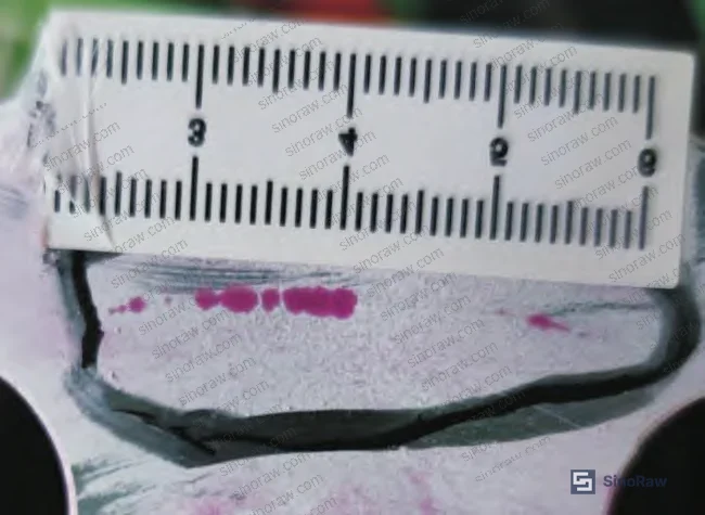
The folding defect itself is a pre-existing manufacturing flaw. Under normal storage or handling, it remains dormant. It only propagates when assembly constraint stress — bolt torquing, weld shrinkage stress, flange face contact loading — acts as the trigger. The fracture at the origin zone shows morphology consistent with high-temperature melt solidification, characteristic of shrinkage porosity — a secondary confirmation that the defect was formed during the original forging heat cycle, not in service.
Material Qualification Results: Why Passing Certs Don’t Catch This #
The chemical analysis and hardness data both confirmed full compliance. This is important for buyers to understand, because it means the valve body was correctly made from the right material — and would pass any incoming inspection protocol that stops at PMI or hardness checks.
Chemical composition (ARL4460 OES, per ASTM A751-21):
| Element | Measured Value | ASTM A350 LF2 CL1 Requirement |
|---|---|---|
| C | 0.17% | ≤ 0.30% |
| Si | 0.23% | 0.15–0.30% |
| Mn | 0.92% | 0.60–1.35% |
| P | 0.022% | ≤ 0.035% |
| S | 0.0016% | ≤ 0.040% |
| Cr | 0.031% | ≤ 0.30% |
| Ni | 0.011% | ≤ 0.40% |
| Mo | 0.0017% | ≤ 0.12% |
Hardness: 175 HBW, tested per ASTM A370-22 on a BH3000 Brinell hardness tester — within the ASTM A350 requirement.
Base metal microstructure: ferrite + pearlite with minor bainite. This is exactly the expected microstructure for LF2 CL1 forgings. Nothing in the bulk material indicates a defective heat or out-of-specification processing.
Honestly, most buyers over-specify the material grade requirements for this valve class while simultaneously under-specifying the surface integrity inspection requirements. The focus goes to chemistry, Charpy impact, and tensile strength — all of which this batch would have passed — while the one test that would have caught the problem (100% surface NDE) is left as an optional or sampling-based activity.
SEM and EDS Analysis: What the Fracture Surface Tells Buyers #
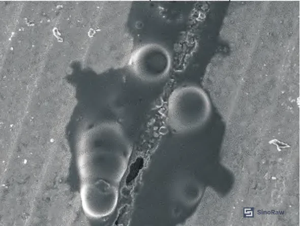
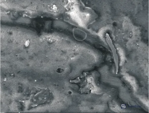
Under SEM, the flange face shows machining plow marks that remain clearly visible beneath the zinc electroplate layer. The cracks near the bolt holes are partially filled with large blocky masses. Crack edges transition smoothly to the surrounding base metal — no sharp protrusions. Cracks widen as they approach the bolt holes, and multiple cracks on both sides of bolt holes share the same morphology and propagation direction, all connecting back to the bolt hole geometry.
This spatial pattern confirms the assembly constraint stress theory. The bolt holes are the stress concentration points. When the valve is bolted to the pipeline flange, the localized stress field around each bolt hole amplifies the constraint stress at existing folding defect sites, driving crack opening and propagation.
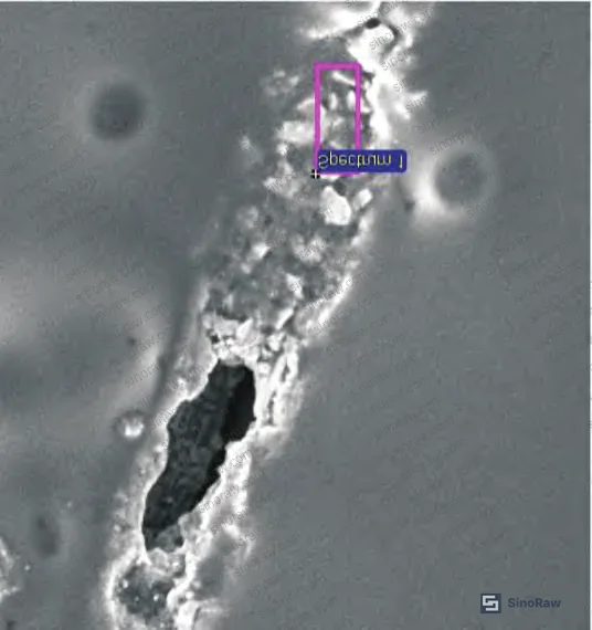
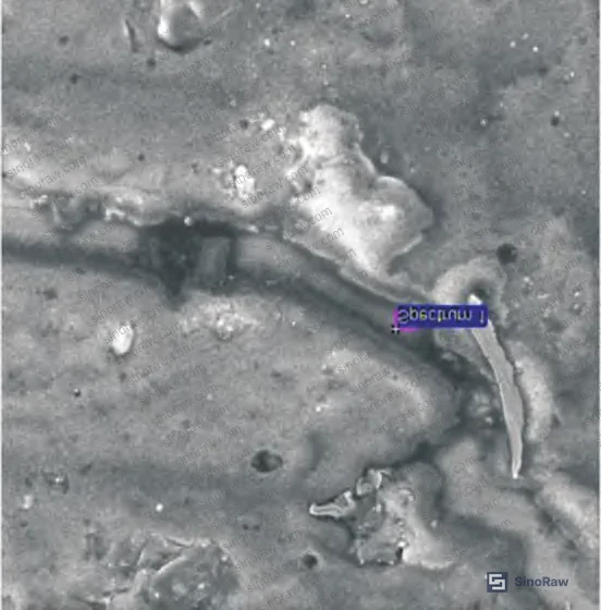
EDS confirmed that the material filling and surrounding the cracks consists primarily of O, Fe, and Zn elements. The zinc presence is consistent with the electroplated surface finish applied to the valve. The oxygen-iron combination at grain boundaries is original forging-scale oxide, not a service-generated corrosion product.
In qualification work involving batches of instrumentation valve bodies from multiple Chinese forges, finding folding defects in valve bodies that otherwise carry full material documentation is not unusual. The problem is not endemic to any single supplier, but it is more prevalent where billet surface preparation — specifically oxide scale removal before hot forging — is treated as a cost-reduction opportunity rather than a quality gate.
Most procurement teams don’t realize that surface NDE requirements for forged valve bodies are frequently left to supplier discretion in standard commercial purchase orders. Unless the buyer explicitly invokes 100% inner and outer surface inspection as a contractual requirement — referencing either the applicable valve standard or project specification — the supplier’s default is often sampling-based inspection at best, and visual-only at worst. The gap between “meets ASTM A350” and “free of forging folding defects” is exactly where these failures originate.
For industrial piping applications where these valves are used as primary isolation at process connections, a failure during installation is actually the best-case outcome. A valve body crack that opens under operating pressure at a Class 900 rated connection is a process safety event.
Relevant acceptance and inspection protocols for this equipment category are addressed in industry guidelines. Buyers working with Class 900 and higher pressure-rated instrumentation valves should also reference IEC 62619:2022 Safety requirements for secondary lithium cells and batteries for any electrically actuated valve variants in battery-adjacent energy storage installations. For broader valve body testing protocol alignment in process systems, the ISO 12405-4 Electrically propelled road vehicles — Test specification for lithium-ion traction battery packs and systems framework provides useful parallels in pressure-system qualification methodology. Process piping valve buyers operating under international procurement frameworks should also review UN 38.3 Recommendations on the Transport of Dangerous Goods — Lithium Battery Testing when these valves appear in multi-hazard transport or storage configurations.
For buyers sourcing broader fluid control hardware including Fluid Control components and Pump & Valve Seals from Chinese manufacturers, the same folding-defect risk applies to any forged body component — gate valves, check valves, pressure-retaining fittings — where billet surface quality upstream of the forge is not controlled.
Practical Guidance for Buyers #
If you are procuring welded flange globe valves in the Class 600–Class 1500 range for oil and gas, refinery, or chemical plant station piping, the single most costly mistake is treating material certification as sufficient incoming quality evidence. Chemistry compliant. Hardness compliant. Folding defect present. All three can be simultaneously true.
The investigation covered here involved a real batch of ASME A350 LF2 CL1 forged valve bodies where penetrant testing — applied only after installation cracking was detected — revealed multiple linear indications across multiple units. One crack, ground to 30 mm depth, still showed clear PT indication. These defects were present when the valves left the factory.
At sinoraw.com, we work with overseas procurement engineers and quality managers to identify and pre-qualify Chinese valve and instrumentation fitting suppliers before RFQs are issued — specifically to verify whether a supplier’s process controls include the billet preparation and 100% NDE steps that separate compliant valve bodies from defect-carrying ones. The ASME A350 material standard tells you what the steel must be. It does not guarantee how the billet was prepared before forging, or whether oxide scale was removed. Those process steps are where the risk lives.
Your purchase order must explicitly require 100% inner and outer surface NDE (penetrant or magnetic particle, as applicable) as a release condition — not a sampling activity. If your supplier cannot provide per-piece NDE records, you are buying on material certs alone, and this failure mode will eventually find you.
Need help identifying qualified suppliers for Class 900 welded flange globe valves with documented 100% surface NDE? Talk to our sourcing team →
Supplier Qualification Questions #
- What is your billet surface preparation procedure prior to hot forging — specifically, what method and equipment are used to remove oxide scale, and what acceptance criterion defines a “clean” billet surface before the forging operation begins?
- For ASME A350 LF2 CL1 forged valve bodies, do you perform 100% inner and outer surface NDE on each piece as a release requirement, or is surface inspection performed on a sampling basis — and can you provide a sample inspection record showing individual piece traceability?
- Your metallographic examination procedure: what etchant and magnification range are used for microstructure verification, and does your QC protocol specifically require evaluation for folding defects and decarburization zones in cross-section samples?
- What is the maximum allowable linear indication length in your PT or MT acceptance criteria for Class 900 / PN150 valve body forgings — and does your specification reject indications at depths below 30 mm when re-tested after grinding?
- Can you provide EDS or elemental analysis data from your last valve body qualification confirming that no iron oxide scale or grain-boundary oxide inclusions are present in the forged body cross-section at depths corresponding to machined surfaces?
Sourcing Checklist #
- ☐ Valve body material confirmed as ASME A350 LF2 CL1 by OES (optical emission spectrometry) with C ≤ 0.30%, Mn 0.60–1.35%, S ≤ 0.040% reported per ASTM A751
- ☐ Brinell hardness documented at ≤ upper limit per ASTM A350 / ASTM A370-22, with test performed on transverse cross-section specimen (measured result: confirm ≤ 197 HBW per LF2 requirements)
- ☐ 100% inner and outer surface NDE (penetrant testing or magnetic particle testing) confirmed as per-piece release requirement — not sampling — with individual piece records traceable to heat and lot
- ☐ PT/MT acceptance criteria explicitly rejects linear indications — no linear indications of any length accepted on pressure-retaining surfaces per applicable valve standard
- ☐ Metallographic qualification report available showing ferrite + pearlite base microstructure with no folding defect indicators (decarburization zones, grain-boundary oxide masses, blunt-tip subsurface cracks) in forging cross-section
- ☐ Billet preparation procedure documented, confirming oxide scale removal step before hot forging, with process control records available for review
- ☐ Weld end dimensions confirmed as 19.05 mm (3/4 in) and/or 12.07 mm (1/2 in) with dimensional inspection report; flange rating confirmed as Class 900 / PN150
Key Specifications Table #
| Parameter | Recommended Value | Verification Method |
|---|---|---|
| Valve body material | ASME A350 LF2 CL1 forging | OES chemical analysis per ASTM A751-21; all elements within grade limits |
| Body hardness | ≤ 197 HBW (LF2 CL1 limit) | Brinell hardness test per ASTM A370-22 on transverse cross-section |
| Surface NDE coverage | 100% inner and outer surface | PT (penetrant testing) or MT per applicable valve standard; zero linear indications accepted |
| Primary crack depth detectability | Indications detectable at ≥ 30 mm grinding depth | PT re-test after progressive grinding; indication must be resolved, not merely absent at surface |
| Crack length rejection threshold | Any linear indication ≥ 1.17 mm depth or ≥ 8.6 mm surface length | Metallographic cross-section measurement and PT/MT surface mapping |
| Microstructure | Ferrite + pearlite (minor bainite acceptable); no decarburization >0.1 mm | Metallographic section etched in 2% nital, observed per GB/T 226 or equivalent |
| Internal components | 316 stainless steel fittings; flexible graphite sealing packing | Material certificates + PMI verification on internal trim |
Can’t find a supplier meeting these specs? Submit your requirements and we’ll match you within 48 hours.
References #
Data source: Failure Analysis of Forging-Induced Folding Defects in Welded Flange Globe Valve Bodies for High-Pressure Station Piping, S.-D. Sun et al., Journal of Materials Engineering and Performance, 2023
Frequently Asked Questions #
What causes folding defects in forged valve bodies?
Folding defects originate during hot forging when oxide scale or surface irregularities on the billet are not removed before the forging operation. As the billet is worked, these surface contamination zones are folded inward and become embedded in the forging. They carry entrapped iron oxide, create a decarburized halo in the surrounding base metal, and remain dormant until a stress trigger — such as assembly bolt torque or weld shrinkage — drives them open into propagating cracks.
Why do valve bodies with correct chemistry and hardness still fail?
Material certification confirms that the steel composition and bulk mechanical properties meet the grade specification. It does not evaluate the forging process quality, billet surface preparation, or the presence of sub-surface folding defects. A valve body can simultaneously pass all ASTM A350 chemistry and hardness requirements and contain pre-existing folding cracks — as confirmed in this investigation. Material certs and process quality are separate, independent attributes.
How deep can folding defects penetrate in a forged valve body?
In the investigated failure, one linear indication remained clearly visible by penetrant testing even after the defect site was ground to a depth of 30 mm. Metallographic cross-sections confirmed primary crack depths of 1.17–1.22 mm through the flange wall thickness at sectioned locations, with surface lengths up to 25 mm. The full depth extent of the defect system through the forging body was not bounded by the 30 mm grinding depth.
Is 100% NDE a standard factory requirement for this valve class?
No — and this is the problem. Standard commercial procurement of ASME A350 LF2 CL1 valve body forgings often defaults to sampling-based surface inspection unless the buyer’s purchase order or project specification explicitly mandates 100% inner and outer surface NDE as a lot release requirement. The cost difference between sampling and 100% NDE is modest relative to the installed cost and consequences of a field failure. Require it explicitly.
What inspection method is most appropriate for detecting folding defects in forged valve bodies?
Liquid penetrant testing (PT) is effective for surface-connected folding defects and was the method used to detect the indications in this investigation. Magnetic particle testing (MT) is an alternative for ferromagnetic steels and provides similar capability. Neither method detects fully sub-surface, non-connected defects — which is why billet surface preparation (oxide scale removal) remains the primary prevention step. For high-criticality applications, supplementary volumetric NDE such as ultrasonic testing should be considered.
Published by sinoraw.com Technical Team | Request a sourcing quote


