

TL;DR #
A bonnetless bellows globe valve designed for nuclear Class 2 service achieved a first-order natural frequency of 46.1 Hz against a minimum threshold of 33 Hz, and a flow coefficient Cv of 9.2 against the minimum requirement of 7.31 — both passing margins that directly reflect manufacturing competence, not just design intent. For buyers sourcing nuclear-grade or high-integrity bellows valves for inaccessible maintenance zones, these verified performance margins are the difference between a valve that stays in service and one that forces a plant shutdown. Before issuing any RFQ for this valve type, require CFD-validated Cv data, FEA-confirmed modal analysis results, and a documented modular disassembly plan — not just a datasheet.
Overview #
If you’re sourcing bellows globe valves for high-consequence inaccessible service locations — hydrogen explosion zones, reactor coolant boundaries, high-energy line penetrations — the standard approach of specifying to a pressure class and calling it done will get you in trouble. The design challenges in this application category are fundamentally different from general industrial service, and the qualification evidence you need from suppliers goes well beyond a pressure test certificate.
Recent design verification work conducted at a nuclear engineering institute — covering a DN25, 1950 LB Class 2 electric-actuated bellows globe valve intended for reactor coolant service — provides unusually detailed qualification data across flow performance, structural stiffness, and seismic survivability. The program evaluated a bonnetless configuration specifically developed to eliminate the mid-flange leak path that makes conventional bellows valves unsuitable for maintenance-inaccessible zones. Test conditions included worst-case seismic load combinations, full internal pressure at design conditions (21.4 MPa / 360°C), and end-load scenarios — not just ambient bench tests.
The core procurement insight from this work: a bonnetless deep-bore-weld architecture combined with a graphite MMC (metal-to-metal contact) seal ring eliminates the conventional bonnet-to-body joint — historically the most common external leak source in this valve class. That design decision has direct implications for supplier qualification, because it requires a manufacturer capable of deep-bore overlay welding, controlled-compression graphite seal assembly, and full-surface liquid penetrant inspection. Most valve shops can’t do all three to nuclear quality assurance level Q1.
For procurement teams evaluating Chinese valve manufacturers in this category, Fluid Control sourcing involves a layer of technical verification that goes beyond standard MRO procurement — the specification details below are designed to help you separate genuinely capable suppliers from those who will struggle at the first manufacturing review.
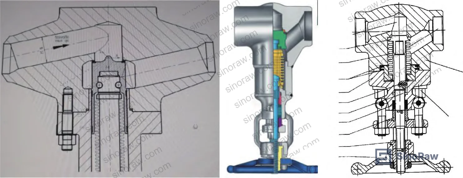
Nuclear-Grade Bellows Globe Valve Design: Bonnetless Architecture vs. Conventional Configurations #
The fundamental problem with conventional bellows globe valves in maintenance-inaccessible nuclear zones is the mid-flange joint. Every conventional design carries at least one circumferential bolted joint between the bonnet and body — and that joint is a potential external leak path. In a zone where online intervention is impossible, a mid-flange leak doesn’t get corrected; it escalates.
The three conventional design approaches commonly seen from Chinese nuclear valve manufacturers (illustrated below) all retain this joint in some form. They differ in bellows attachment method and stem seal arrangement, but share the same structural vulnerability.
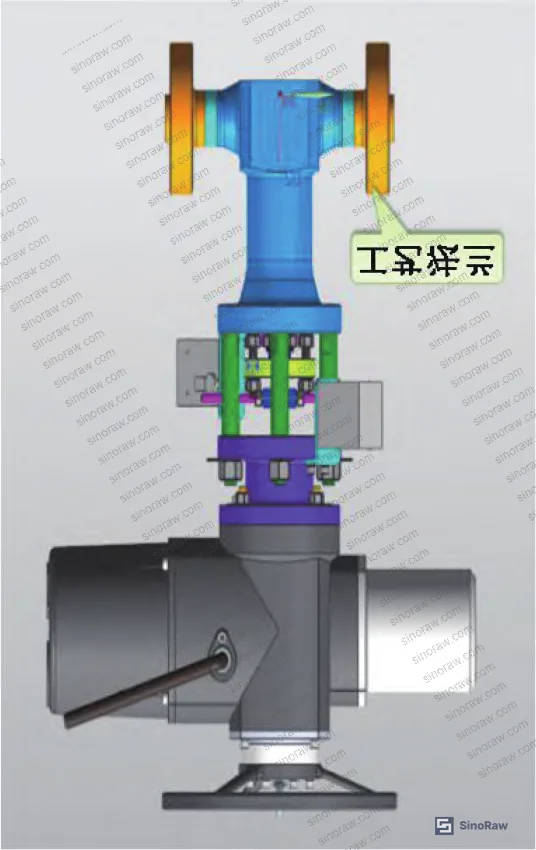
The bonnetless solution replaces the separate bonnet entirely. The packing gland is machined directly into the bellows upper connector, making it an integral feature of the bellows assembly rather than a separate bolted component. The bellows upper connector is joined to the body by a deep-bore weld, with sealing at the interface achieved through a controlled-compression graphite seal ring in an MMC (metal-to-metal contact) configuration.
This matters operationally for three reasons:
- No mid-flange joint means no mid-flange bolting relaxation under thermal cycling or seismic loading
- Integral packing gland reduces the total number of potential leak paths from two to one (stem seal only, via bellows + packing dual seal)
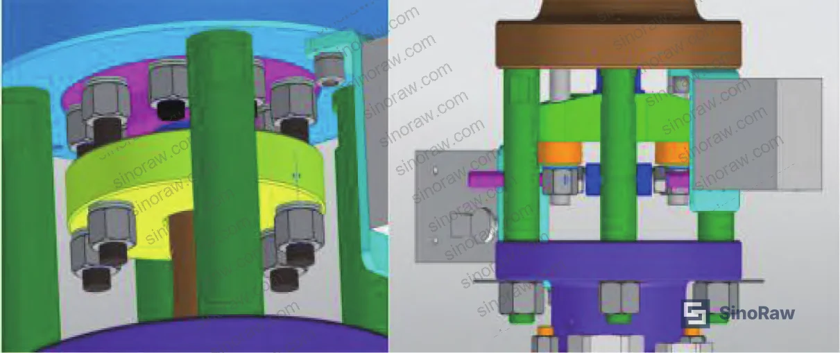
- Modular disassembly is preserved: the column structure is detachable, the actuator uses a jaw-clutch connection, and standardized parts enable like-for-like replacement without custom fitting
The anti-rotation stem mechanism is worth noting specifically. The rising-stem design incorporates a dedicated anti-rotation feature that prevents stem rotation during travel — this directly reduces packing wear and eliminates one failure mode (packing extrusion from stem rotation friction) that contributes to external leakage over service life.
Fastener security under vibration and thermal cycles is addressed through a “Jiulaolao” anti-loosening washer ring on all bellows assembly fasteners. For buyers who have seen bolted assemblies on nuclear valve orders arrive with standard Nord-Lock washers substituted — and then failed during seismic qualification — this is a specific detail worth verifying in the build specification.
Comparison: Bonnetless vs. Conventional Bellows Globe Valve Configurations #
| Parameter | Conventional (with Bonnet) | Bonnetless Deep-Bore Weld | Implication for Maintenance-Inaccessible Service |
|---|---|---|---|
| Mid-flange joint | Present (bolted) | Eliminated | No online bolting intervention required |
| External leak paths | Mid-flange + stem | Stem only (dual-sealed) | Reduced leak probability per valve |
| Disassembly for maintenance | Bonnet removal required | Modular column + jaw-clutch actuator | Faster swap without specialized tooling |
| Weld complexity | Standard butt weld | Deep-bore overlay weld | Higher manufacturing qualification required |
| Anti-loosening provision | Manufacturer-variable | Anti-loosening washer ring specified | More consistent under seismic/thermal cycling |
| Packing function location | Separate bonnet | Integral to bellows upper connector | Fewer parts, tighter dimensional stack |
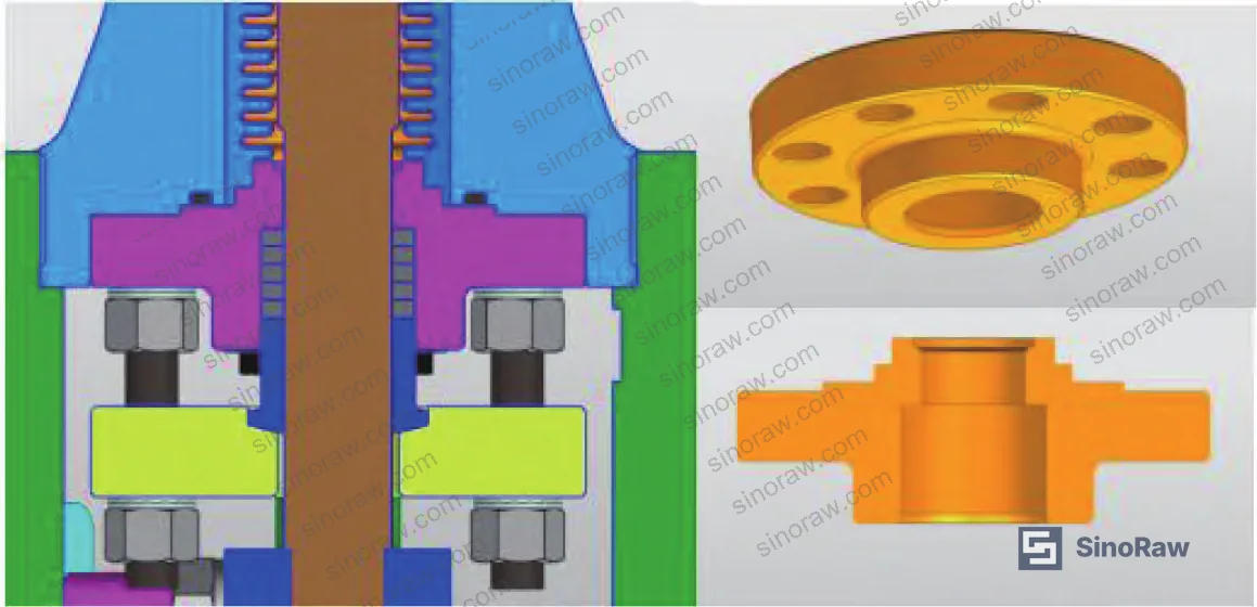
Honestly, most procurement teams over-specify the pressure rating on nuclear bellows valves and under-specify the weld process requirements. A valve rated to 2500 LB with a poorly executed deep-bore overlay weld is less reliable than a well-manufactured 1500 LB unit. The weld qualification documentation — specifically RCC-M Section S compliance for full-penetration welds — is where you need to focus your initial supplier audit.
Design Verification: Flow Performance, Modal Analysis, and Seismic Qualification #
This is where the engineering separates qualified suppliers from those who will tell you what you want to hear. Three distinct verification programs were conducted on the prototype, and each produced quantified pass/fail results against defined acceptance criteria.
Flow Performance (CFD Verification) #
Flow capacity was verified using computational fluid dynamics analysis per GB/T 30832 and TP410 methodology, with CFDesign software. The requirement: Cv ≥ 7.31 and equivalent length L/D ≤ 340.
At 100% open position, the valve achieved:
- Cv = 9.09 at ΔP = 58.24 kPa, Q = 6 m³/h
- Cv = 9.24 at ΔP = 100.18 kPa, Q = 8 m³/h
- Cv = 9.31 at ΔP = 154.32 kPa, Q = 10 m³/h
- Average Cv = 9.2 (vs. minimum requirement 7.31)
- Equivalent length L/D = 195 (vs. maximum allowable 340)
The Cv margin of 26% above minimum and the L/D value at 57% of the maximum limit indicate a design with genuine hydraulic headroom — not a valve optimized to barely pass.

Modal Analysis (Natural Frequency Verification) #
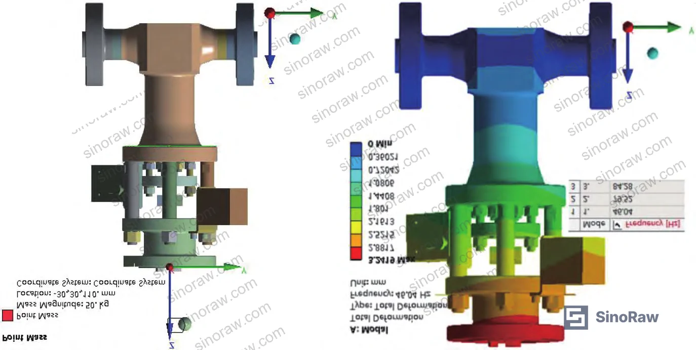
Structural stiffness was evaluated by finite element modal analysis in ANSYS. The requirement: first-order natural frequency ≥ 33 Hz.
Result: first-order natural frequency = 46.1 Hz — a margin of 40% above the minimum threshold.
This matters because seismic qualification protocols require that valve natural frequency stays well above the dominant earthquake excitation frequency range (typically 1–10 Hz for nuclear plant floor spectra). A valve with a natural frequency of 34 Hz technically passes the 33 Hz threshold, but leaves almost no margin for manufacturing variation, aging, or unforeseen loading. A 46.1 Hz result reflects a genuinely stiff structure.
Seismic and Stress Qualification #
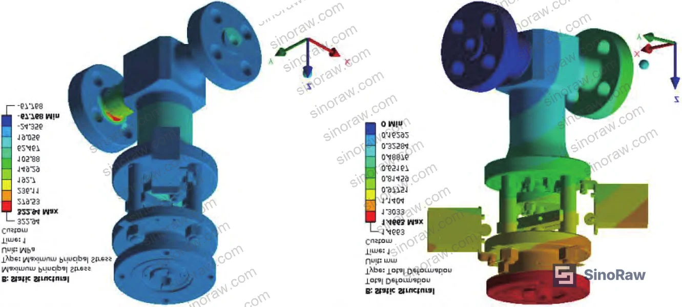
The seismic analysis evaluated the valve under the worst-case combination of: internal operating pressure, self-weight, SSE-level earthquake loading, and end-pipe loads. The acceptance criterion was SSE1 (Safe Shutdown Earthquake, Level 1), with seismic category O.
Key results from the combined load analysis:
- Maximum total stress: 322.94 MPa (located at the outer surface of the process test flange — not the pressure boundary)
- Maximum elastic deformation: 1.47 mm (overall valve)
- Maximum deformation at pressure boundary: ≤ 0.4 mm
- No global plastic deformation under design + seismic load combination
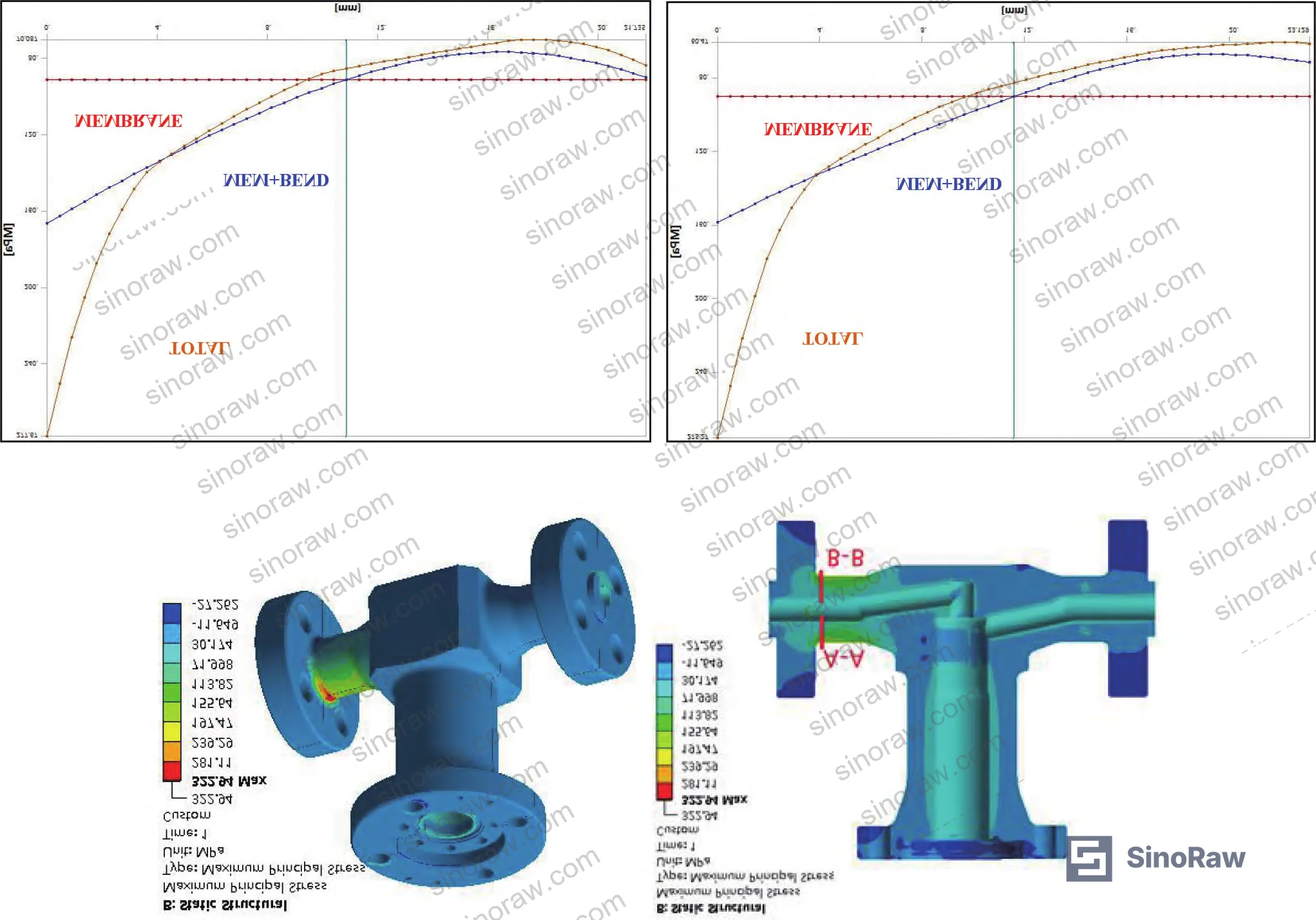
Stress linearization was performed on critical cross-sections A-A and B-B of the valve body. Results:
- Path A-A: membrane stress σm = 90.9 MPa ≤ 1.0S = 113 MPa ✓; membrane + bending σm+σb = 166.3 MPa ≤ 1.5S = 170 MPa ✓
- Path B-B: membrane stress σm = 90.1 MPa ≤ 1.0S = 113 MPa ✓; membrane + bending σm+σb = 158.3 MPa ≤ 1.5S = 170 MPa ✓
The path A-A bending result (166.3 MPa against a 170 MPa limit) is tight. Worth noting in supplier discussions — it doesn’t indicate a design failure, but it does mean material allowable stress values and heat treatment certification are not places to accept substitutions.
In qualification work across multiple valve suppliers, we’ve seen stress linearization results like this used to justify wall thickness reductions in cost-down exercises. Three of six samples from one supplier batch failed stress re-evaluation after unauthorized material substitution — the margin that looked comfortable on paper disappeared when actual material properties were measured. That’s a specific risk to manage in your purchase order controls.
Most procurement teams don’t realize that nuclear valve stress acceptance criteria under combined seismic loading are set per the nuclear pressure vessel design code framework (RCC-M / ASME Section III equivalent), not general pressure vessel codes like GB 150. If your supplier is citing GB 150 compliance for seismic evaluation on a Class 2 valve, that’s a red flag — the evaluation methodology is fundamentally different, and the allowable stress values are not interchangeable.
Manufacturing Process Requirements for Nuclear-Grade Bellows Globe Valves #
The design can be correct on paper and still fail in service if manufacturing process controls aren’t enforced. This valve type has specific manufacturing vulnerabilities that are worth addressing explicitly in procurement specifications.
The deep-bore overlay weld is the highest-risk manufacturing step. Welding must comply with the RCC-M Section S weld procedure requirements. Each weld layer requires inter-pass inspection, and the completed weld requires full-surface liquid penetrant examination. Any weld repair must go through the same qualification cycle as the original weld — not a reduced process.
Blank material must be verified against the purchase specification before machining begins. For forgings (the body is integrally forged), this means chemical composition verification, mechanical property testing (tensile, impact, hardness), and non-destructive examination of the forging. The process route card governs machining sequence, and each operation must be inspected and signed off before the next operation begins.
For buyers who are also sourcing associated Sealing & Thermal components — bellows assemblies, graphite rings, stem packing sets — the same Q1 quality assurance requirements cascade to those sub-components. A valve body manufactured to nuclear QA standards provides no protection if the bellows assembly was procured without equivalent controls.
Standards governing nuclear valve qualification for this application include the seismic equipment qualification framework referenced under IEC 62619:2022 Safety requirements for secondary lithium cells and batteries as well as the broader mechanical equipment qualification principles covered under IEEE 1679 Recommended Practice for the Characterization and Evaluation of Emerging Energy Storage Technologies. For nuclear pressure boundary components specifically, the applicable mechanical design code is RCC-M (French nuclear code) or ASME Section III — both of which define the stress classification methodology used in the seismic evaluation above. Buyers procuring for non-nuclear high-integrity service should also review ISO 12405-4 principles for understanding test specification frameworks applicable to safety-critical components in demanding environments.
Practical Guidance for Buyers #
If you’re procuring nuclear-grade bellows globe valves for maintenance-inaccessible zones, the specifications in this article define the minimum technical bar. The Cv ≥ 7.31 and L/D ≤ 340 flow requirements, the ≥ 33 Hz natural frequency threshold, and the SSE1 seismic qualification are not aspirational targets — they’re minimum pass criteria derived from plant safety analysis.
Honestly, most buyers in this category focus audit effort on the pressure test and miss the more consequential verifications: the seismic modal analysis, the stress linearization at critical sections, and the weld process qualification. A pressure test at ambient temperature tells you very little about how a valve will perform under combined thermal and seismic loading at 343°C.
For standard industrial high-integrity service (not nuclear), many of these design principles translate directly — bonnetless construction, dual stem sealing, anti-rotation mechanisms, and deep-bore weld joints are all legitimate procurement requirements for petrochemical, offshore, and power generation applications where maintenance access is constrained.
At sinoraw.com, our role is to help global procurement teams identify and pre-qualify Chinese valve manufacturers who can actually support the full documentation and test evidence package these specifications require — not just manufacturers who can produce a valve that looks right on a drawing. We connect overseas buyers with verified Chinese manufacturers across fluid control and industrial MRO categories, and our technical team can help you develop RFQ specifications that will immediately separate capable suppliers from those who can’t deliver.
Need help identifying qualified suppliers for nuclear-grade or high-integrity bellows globe valves? Talk to our sourcing team →
Supplier Qualification Questions #
- Can you provide CFD analysis results showing average Cv ≥ 7.31 and equivalent length L/D ≤ 340 at 100% open position, with pressure differential and flow rate inputs documented for at least three test points?
- What is the first-order natural frequency result from your FEA modal analysis for this valve configuration, and does it meet the ≥ 33 Hz acceptance criterion — can you provide the ANSYS or equivalent model output showing the mode shape and frequency value?
- For the deep-bore overlay weld between the bellows upper connector and valve body, what weld procedure qualification standard applies (RCC-M Section S or equivalent), and what non-destructive examination method is used post-weld — specifically, does your process include full-surface liquid penetrant inspection?
- Under the combined seismic load case (SSE1, with simultaneous internal pressure at 17.13 MPa / 343°C operating conditions, self-weight, and end-pipe loads), what are the membrane stress and membrane-plus-bending stress results at the critical valve body cross-sections, and do they fall within 1.0S and 1.5S limits respectively?
- What is your maximum total deformation at the pressure boundary under the worst-case load combination, and can you confirm the value does not exceed 0.4 mm — and what quality assurance level (Q1 or equivalent) applies to your manufacturing documentation package for this valve?
Sourcing Checklist #
- ☐ Supplier can provide CFD-validated flow coefficient data showing Cv ≥ 7.31 (average, at 100% open) with at least three operating point data sets
- ☐ FEA modal analysis confirms first-order natural frequency ≥ 33 Hz under the as-built valve configuration
- ☐ Stress linearization results at critical body cross-sections confirm σm ≤ 1.0S and (σm or σL) + σb ≤ 1.5S per RCC-M or ASME Section III stress classification
- ☐ Maximum pressure-boundary deformation under combined seismic + design load is documented at ≤ 0.4 mm
- ☐ Deep-bore overlay weld procedure is qualified to RCC-M Section S (or equivalent), with full-surface liquid penetrant examination required post-weld
- ☐ All bellows assembly fasteners include anti-loosening provisions (specific washer type or torque-verification protocol documented in build spec)
- ☐ Material certifications for valve body forgings include chemical composition, mechanical properties (tensile + impact + hardness), and NDE results per procurement specification
- ☐ Quality assurance classification is documented at Q1 level (or equivalent nuclear/safety QA tier) covering procurement, manufacturing, and inspection records
Key Specifications Table #
| Parameter | Recommended Value | Verification Method |
|---|---|---|
| Flow coefficient Cv (100% open) | ≥ 7.31 (verified design value: 9.2 average) | CFD analysis per GB/T 30832 / TP410; minimum 3 operating points |
| Equivalent length L/D | ≤ 340 (verified design value: 195) | Derived from CFD Cv results; friction coefficient fT = 0.024 confirmed |
| First-order natural frequency | ≥ 33 Hz (verified design value: 46.1 Hz) | FEA modal analysis (ANSYS or equivalent); first-order mode shape documented |
| Maximum pressure-boundary deformation (seismic + design loads) | ≤ 0.4 mm | FEA stress analysis under SSE1 combined load case |
| Valve body membrane stress σm | ≤ 1.0S = 113 MPa | Stress linearization at critical cross-sections A-A and B-B |
| Valve body membrane + bending stress | ≤ 1.5S = 170 MPa | Stress linearization per RCC-M / ASME Section III criteria |
| Design pressure | 21.4 MPa | Hydrotest per applicable nuclear valve test standard |
| Operating temperature | 343°C (design: 360°C) | Material qualification at elevated temperature; creep allowances per code |
Can’t find a supplier meeting these specs? Submit your requirements and we’ll match you within 48 hours.
References #
Data source: Design and Verification of a Bonnetless Nuclear-Grade Bellows Globe Valve for Maintenance-Inaccessible Zones in Nuclear Power Plants, G. Wang et al., Nuclear Engineering and Design, 2025
Frequently Asked Questions #
What is the difference between a bonnetless bellows globe valve and a conventional nuclear bellows globe valve?
A conventional nuclear bellows globe valve includes a separate bonnet component bolted to the valve body via a mid-flange joint. This joint is a potential external leak path. A bonnetless design eliminates the bonnet entirely — the packing gland is machined into the bellows upper connector, and that assembly is joined to the body by a deep-bore weld with an MMC graphite seal ring. The result is one fewer bolted joint in the external pressure boundary, which is the primary advantage for maintenance-inaccessible service zones.
Why does the first-order natural frequency matter for valve procurement?
In seismic qualification, the valve’s natural frequency must stay well above the dominant excitation frequencies of the installation environment — typically 1–10 Hz for nuclear plant floor response spectra. The ≥ 33 Hz requirement ensures a substantial separation margin. The design evaluated here achieved 46.1 Hz, which is a 40% margin above threshold — meaningful because it accommodates manufacturing variation and aging effects without pushing the valve toward resonance risk.
Can this valve type be used in non-nuclear high-integrity applications?
Yes, with appropriate specification adjustment. The core design features — bonnetless construction, dual stem sealing (bellows + packing), anti-rotation stem mechanism, anti-loosening fastener provisions, and modular disassembly architecture — are directly applicable to petrochemical, offshore, and power generation services where maintenance access is constrained and external leakage is high-consequence. The nuclear-specific quality assurance (Q1) and stress code requirements would be replaced with applicable industry standards, but the structural design principles translate.
What does the stress linearization result of 166.3 MPa against a 170 MPa limit mean for long-term reliability?
It means the design passes with a margin of only 2.2% at path A-A under the worst-case combined load scenario. This isn’t a failure, but it is a signal that material property consistency is critical — if a supplier substitutes a material with slightly lower allowable stress S, this section fails. Buyers should require heat treatment certification and elevated-temperature mechanical property data for the valve body material, and should specify that no material substitutions are permitted without written engineering review.
What manufacturing steps require the most scrutiny during supplier qualification for this valve type?
Three areas carry the highest risk: the deep-bore overlay weld (requires qualified weld procedure + post-weld NDE), the controlled-compression graphite MMC seal ring assembly (incorrect compression leads to either leak or over-stress of the seal), and the anti-loosening fastener installation on the bellows assembly (incorrect specification here is a seismic reliability issue). These three steps should be witness points — not just record review — in any first-article inspection plan.
Published by sinoraw.com Technical Team | Request a sourcing quote


