

TL;DR #
Sealing surface scratches and micro-pits account for over 90% of isolation valve failures in high-temperature gas-cooled reactor helium circuits — cracks and porosity combined represent fewer than 10% of all damage cases. For procurement teams specifying maintenance-compatible valve designs, this means coaxiality tolerance at the grinding tool interface is the single most critical dimension to specify and verify. Before issuing RFQs for helium isolation valves or their associated in-situ repair tooling, confirm that the supplier can hold sealing surface coaxiality error below ±0.08 mm through the full grinding stroke.
Overview #
If you’re sourcing isolation valves for helium-circuit service in Generation IV reactor applications, the maintenance strategy needs to be part of the original procurement scope — not an afterthought. Most buyers specify the valve itself and ignore the serviceability constraint entirely, then discover mid-outage that the valve is weld-connected to the primary circuit and physically cannot be removed for bench refurbishment. That’s an expensive realization.
The technical data referenced throughout this article originates from a structured R&D program conducted at a Chinese nuclear reactor system design laboratory, working jointly with an operational nuclear power site. The research team designed dedicated grinding maintenance equipment, fabricated full-scale valve simulants in austenitic stainless steel with hardmetal sealing faces, and validated the entire repair cycle on a purpose-built helium leak detection test rig. This is applied engineering work with documented test results — not theoretical analysis.
Helium isolation valves in high-temperature gas-cooled reactors (HTGRs) serve as the primary flow control element in the reactor helium coolant circuit. They cycle repeatedly under high temperature, high pressure, and high-velocity helium flow. Even when sealing faces are manufactured from wear-resistant, corrosion-resistant, high-temperature creep-resistant hardmetal alloys, surface degradation is essentially unavoidable over extended service life. The key question for procurement engineers isn’t whether the valve will need maintenance — it will — but whether the valve and its supporting tooling ecosystem are designed to enable that maintenance without circuit isolation or component removal.
For buyers sourcing fluid control components destined for critical-service applications, this evaluation framework applies broadly beyond nuclear service: any isolation valve in a welded circuit that cannot be hot-swapped benefits from the same in-situ grinding logic.
Helium Isolation Valve Failure Modes: What the Data Actually Shows #
Understanding the failure mode distribution changes how you write specifications. The data is unambiguous.
There are three primary failure categories for helium isolation valve sealing faces:
Crack defects — The sealing face operates under combined high-temperature, high-pressure loading with thermal cycling stress. Micro-cracks can initiate at the sealing face surface. These are real but relatively rare in practice.
Porosity defects — During hardfacing deposition (overlay welding of the hardmetal sealing surface), gas entrapment can leave subsurface voids. Over service life, repeated fluid erosion gradually thins the sealing face layer until those voids emerge as surface pores.
Scratches and micro-pits — Helium in the circuit carries trace particulate contamination. Each open/close cycle drags those particles across the sealing face. Over thousands of cycles, the cumulative effect is a sealing face covered in micro-scratches and shallow pits that break the required surface contact geometry.
The failure mode distribution is where this gets operationally important: cracks and porosity together account for fewer than 10% of total valve damage cases. Scratches and micro-pits drive more than 90% of sealing performance degradation and outright failures.
This matters enormously for specifying repair capability. Crack and porosity damage generally cannot be remediated by surface grinding — those valves are typically scrapped or require weld repair. But the dominant failure mode — surface scratches and micro-pits — is fully addressable by precision rotary grinding, which means a large majority of damaged valves are candidates for in-situ restoration rather than replacement.
| Failure Mode | Prevalence | Grindable? | Typical Cause |
|---|---|---|---|
| Cracks | < 5% of cases | No — requires weld repair or replacement | Thermal cycling stress, high-pressure loading |
| Porosity (pinholes) | < 5% of cases | No — subsurface origin | Gas entrapment during hardfacing deposition |
| Scratches & micro-pits | > 90% of cases | Yes — primary target for in-situ grinding | Particulate erosion during valve cycling |
Honestly, most procurement specifications for nuclear-grade isolation valves focus extensively on material grades and pressure ratings but say nothing about sealing face repairability criteria. That’s a gap. If your valve spec doesn’t address maintenance strategy at the sealing face level, you’re leaving significant lifecycle cost risk on the table.
In-Situ Grinding Maintenance: Equipment Design and Critical Parameters #
Because HTGR helium circuit isolation valves are weld-connected and cannot be removed for off-site repair, the maintenance approach must be fully in-situ. The research program evaluated three grinding method categories — manual, semi-automatic, and fully automatic — before selecting fully automatic as the only viable option for this application.
Manual grinding depends on operator skill and experience. Inexperienced operators risk causing irreversible sealing face damage. Semi-automatic methods still require human intervention at key process steps; incorrect intervention can cause localized sealing face damage. Only fully automatic grinding eliminates operator-induced variability and can be deployed in a radiologically controlled environment with minimal personnel exposure time.
The fully automatic equipment set was designed to meet five operational requirements: compact and portable enough for single-person transport, installation completable within 5 minutes, zero human intervention during the grinding operation, adaptable across different valve sizes, and all operating parameters pre-validated through repeated test cycles.
Valve Seat (Body-Side) Grinding Equipment #
The valve seat remains in the circuit and cannot be removed. The grinding tool must therefore locate itself precisely against the valve body internal bore geometry.
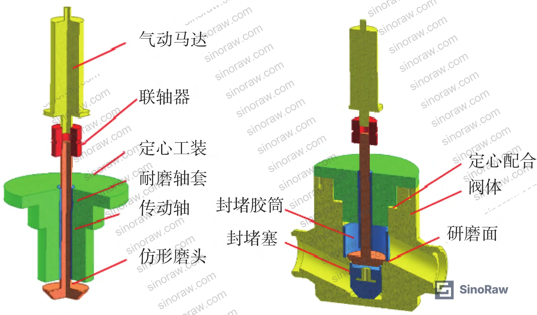
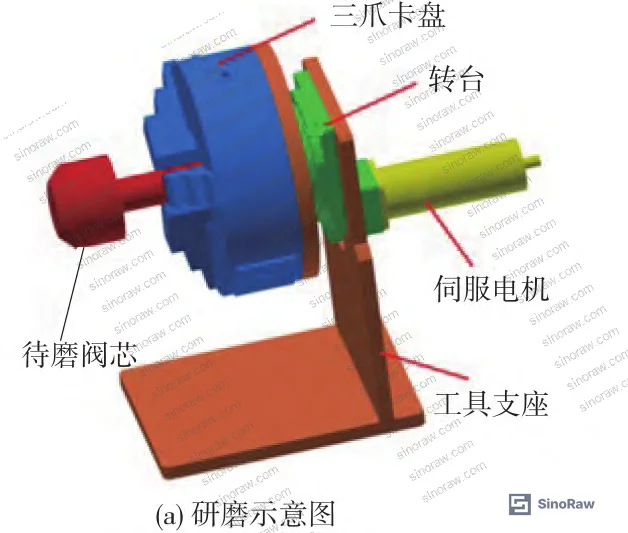
The seat grinding tool comprises a pneumatic motor, coupling, centering fixture, wear-resistant bushing, drive shaft, and profiled grinding head. Each component serves a specific coaxiality or force-control function:
- The pneumatic motor speed is controlled via an inlet throttle valve regulating compressed air flow rate
- The centering fixture is manufactured from precision-machined PEEK engineering plastic, located against the valve body internal bore wall with a coaxiality error of approximately ±0.02 mm
- The centering fixture inner bore mates with the wear-resistant bushing with a coaxiality error below ±0.02 mm
- The drive shaft passes through the wear-resistant bushing with a clearance fit, coaxiality error below ±0.04 mm
- The profiled grinding head maintains a coaxiality error relative to the valve seat sealing face below ±0.08 mm
That ±0.08 mm coaxiality figure at the grinding face is the critical output. Everything in the tooling design is engineered to stay within that envelope. A ball-and-socket joint between the profiled grinding head and the drive shaft provides self-adaptive compliance, allowing the head to seat naturally against the sealing face geometry rather than impose a rigid angle.
Grinding pressure is controlled through the tool’s own weight — calculated component masses are used to set the applied normal force within a defined working range.
Valve Plug (Removable) Grinding Equipment #
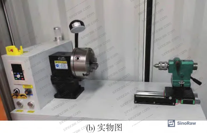
The valve plug (disc/cone) can be physically removed from the circuit. It is mounted in a small horizontal-lathe-type fixture comprising a three-jaw chuck, rotary table with integrated reduction gear set, servo motor with adjustable speed output, and tool support bracket.
The three-jaw chuck secures the plug and maintains its rotation on the grinding centerline. The reduction gear set in the rotary table steps down the servo motor speed while maintaining adequate torque. The servo motor allows precise rotational speed control. The profiled grinding head is applied against the rotating plug sealing face via a tail-center pressure spindle.
For plug grinding, coaxiality control measures include: adjusting three-jaw chuck and tail center concentricity within tolerance, maximizing the plug clamping engagement length to reduce runout, and managing plug rotational speed to minimize dynamic deflection effects. Applied grinding force is measured directly via a pressure sensor mounted behind the tail center — the only force-measurement approach used in this equipment set.
Key Operating Parameters #
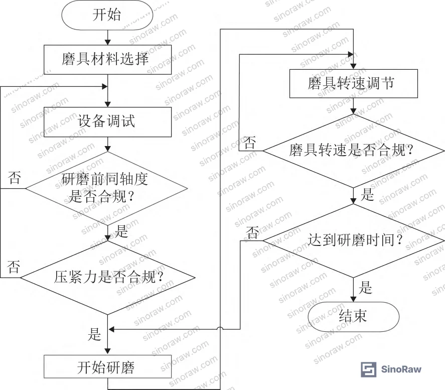
Five parameters govern grinding outcome quality: abrasive material, coaxiality of the grinding tool relative to the sealing face, applied contact force, rotational speed, and grinding time. These parameters are interdependent. Higher abrasive hardness and grit size increase material removal rate but reduce surface finish control. Higher contact force and higher rotational speed both increase removal rate but reduce precision and degrade coaxiality stability. Grinding time is determined by the combined effect of all other parameters and requires empirical validation — there is no reliable analytical shortcut.
The process follows a defined sequence: select abrasive material → set coaxiality → set contact force → set rotational speed → grind to time → inspect sealing face geometry and roughness → reassemble if criteria met, or continue grinding cycle if not.
Test Rig Design and Sealing Performance Verification #
The validation program used purpose-built valve simulants and a test rig designed specifically to replicate helium circuit sealing performance conditions.
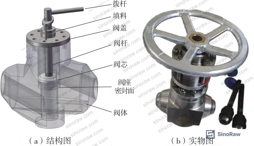
Valve Simulants #
The simulants replicate the key mechanical elements of actual HTGR helium isolation valves: valve body (seat), plug, stem, bonnet, packing, and handwheel/lever operator. Non-essential components (electric actuator head) were omitted to focus validation on sealing face behavior. Body material is austenitic stainless steel; sealing faces are hardmetal alloy overlay — the same material combination used in service.
Artificial defects (scratches, micro-pits matching the dominant failure mode) were introduced into the simulant sealing faces, the in-situ grinding process was applied, and the ground simulants were then installed on the test rig for leak testing.
Test Rig #
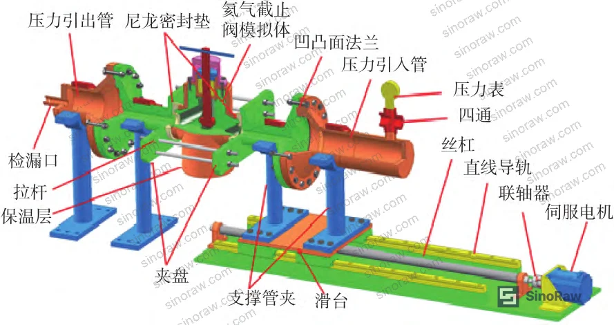
The test rig incorporates a servo motor-driven sliding table assembly with a 900 mm stroke linear guide. The stroke design accommodates valve length variation of approximately 730 mm across the range of sizes tested, with margin. The single linear rail rated load is 3,280 kg; the paired rail system that supports the sliding table carries a load capacity exceeding 6,000 kg — well above the 1,935 kg mass of the largest valve simulant tested. The rig includes pressure gauges, inlet and outlet manifolding, a helium leak detector instrument at the outlet, and a dedicated bypass compressed-air purge circuit.
Test Protocol #
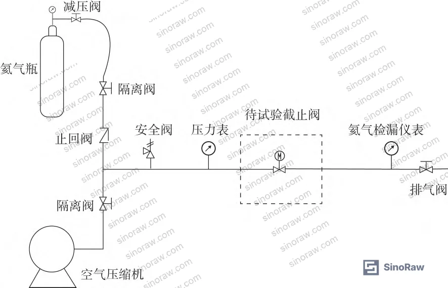
The sealing test sequence runs in two stages. First, with the valve closed, compressed air is introduced to the inlet and pressurized to the test target. Packing seal integrity is checked first to eliminate any packing leakage that could contaminate the subsequent sealing face measurement. Once packing integrity is confirmed, the circuit is purged with compressed air to remove residual test gas.
Second, helium is introduced to the inlet at test pressure. The helium leak detector instrument on the outlet pipe monitors leakage past the valve seat-to-plug sealing interface. The test verifies that post-grinding sealing performance meets the internal leakage standard.
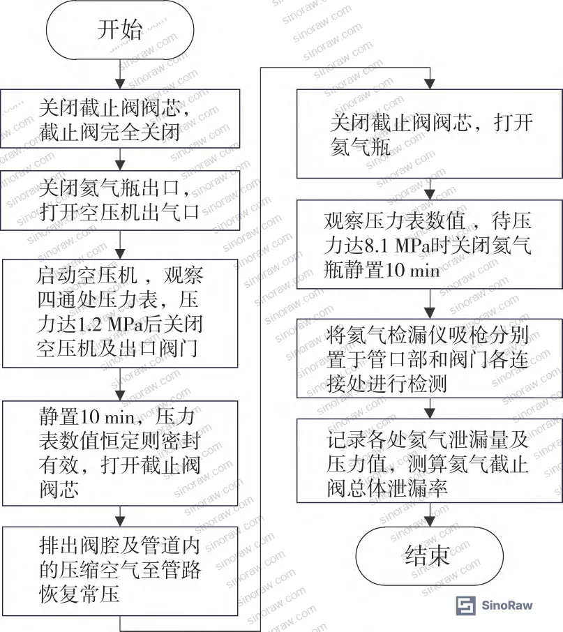
In supplier qualification testing conducted during this research program, all simulant valves that underwent the full grinding process per the validated parameter set passed the helium leak test to the internal leakage standard. The result directly validates the feasibility and effectiveness of in-situ grinding as a maintenance method.
Practical Guidance for Buyers #
If you’re procuring helium isolation valves for Generation IV reactor circuits — or more broadly, any critical isolation valve in a welded-in circuit — there are a few procurement decisions that will determine whether your maintenance strategy succeeds or becomes a crisis.
First: establish sealing face repairability requirements in the original valve specification. This means specifying the hardmetal overlay material (hardness grade, thickness), the sealing face geometry (cone angle, surface roughness target), and the design clearances that allow in-situ grinding tooling to access the seat. If the valve body internal geometry doesn’t accommodate a centering fixture, in-situ grinding becomes mechanically impossible regardless of what the supplier claims.
Second: require that the valve supplier either provides matched grinding tooling or demonstrates compatibility with a validated third-party grinding system. The coaxiality chain from centering fixture to grinding head must be documented — the ±0.08 mm final tolerance at the grinding face is not achievable without validated tooling design.
Third: don’t accept supplier claims about sealing face maintenance capability without seeing actual test data. Ask for leak test results on ground simulants, using helium as the test medium, at rated pressure. Compressed air tests alone are insufficient for helium service qualification.
At sinoraw.com, our team works directly with procurement engineers and technical buyers to identify and pre-qualify Chinese suppliers of critical-service fluid control components — including isolation valves for demanding gas-circuit applications. If you need to locate manufacturers who can supply maintenance-ready valve designs with documented sealing performance data, we can help narrow the field before you issue RFQs.
Need help identifying qualified suppliers for helium isolation valves or in-situ grinding maintenance equipment? Talk to our sourcing team →
Supplier Qualification Questions #
- What is the final coaxiality error specification between your profiled grinding head and the valve seat sealing face centerline, and can you provide dimensional validation data showing this is maintained below ±0.08 mm throughout the grinding stroke?
- What is the coaxiality error specification of your centering fixture relative to the valve body internal bore, and does your design achieve ±0.02 mm or better through precision-machined PEEK or equivalent engineering plastic interface?
- For grinding pressure control on the valve plug (removable element), do you use a pressure sensor at the tail center spindle for real-time force measurement, and what is the specified applied force range in your validated parameter set?
- Can you provide helium leak test results on valve simulants after in-situ grinding, with the valve closed, using helium at rated circuit pressure — specifically confirming the result meets the internal leakage standard, not merely a compressed-air test?
- What is the installation time specification for your in-situ grinding equipment, and can you demonstrate compliance with a 5-minute installation target, given that radiological exposure time minimization is an operational constraint in the service environment?
Sourcing Checklist #
- ☐ Valve sealing face coaxiality tolerance at grinding tool interface is documented at ≤±0.08 mm in supplier technical specification
- ☐ Centering fixture coaxiality error relative to valve body internal bore is ≤±0.02 mm, verified by dimensional inspection report
- ☐ Drive shaft coaxiality error through wear-resistant bushing is ≤±0.04 mm, confirmed by design calculation or measurement data
- ☐ Grinding equipment installation cycle time is ≤5 minutes, confirmed by timed installation demonstration or factory acceptance test record
- ☐ Sealing performance validation uses helium leak detection (not compressed air only), with test results showing conformance to internal leakage standard after grinding
- ☐ Test rig sliding table stroke is ≥900 mm, accommodating valve length variation of at least 730 mm across the specified valve size range
- ☐ Valve simulant body material is austenitic stainless steel with hardmetal alloy sealing face overlay — confirmed by material certification and hardness test report
- ☐ Packing seal integrity is verified independently before sealing face leak test, per the two-stage test protocol, to avoid measurement interference
Key Specifications Table #
| Parameter | Recommended Value | Verification Method |
|---|---|---|
| Grinding head coaxiality to sealing face | ≤±0.08 mm | Dimensional inspection of assembled grinding tool; runout measurement at grinding head face |
| Centering fixture coaxiality to valve bore | ≤±0.02 mm | Precision bore gauge measurement; fixture-to-bore fit verification |
| Drive shaft coaxiality through bushing | ≤±0.04 mm | Shaft runout measurement; clearance fit dimensional check |
| Sliding table stroke (test rig) | ≥900 mm | Linear encoder or mechanical measurement of travel range |
| Maximum valve simulant mass accommodated | ≥1,935 kg | Rail load capacity specification; paired linear rail rating ≥6,000 kg total |
| Linear rail rated load (single rail) | ≥3,280 kg | Manufacturer load rating documentation; application load calculation |
| Equipment installation time | ≤5 min | Timed installation trial; factory acceptance test record |
| Helium leak test pressure | At rated circuit pressure | Pressure gauge calibration record; test protocol documentation |
Can’t find a supplier meeting these specs? Submit your requirements and we’ll match you within 48 hours.
References #
Data source: In-Situ Rotary Grinding Maintenance of Helium Gas Isolation Valve Sealing Faces in High-Temperature Gas-Cooled Reactor Circuits, K.-P. Qian et al., Nuclear Engineering and Design, 2025
Frequently Asked Questions #
Why can’t helium isolation valves in HTGR circuits simply be replaced when sealing performance degrades?
Most HTGR helium circuit isolation valves are connected to the system piping by welded joints rather than flanged or threaded connections. Removing a welded-in valve requires cutting the circuit, which is a major maintenance event with significant radiation exposure implications, extended outage duration, and high cost. In-situ grinding addresses sealing face degradation — which causes more than 90% of valve failures — without any circuit disconnection.
What surface defects can in-situ grinding actually repair?
In-situ rotary grinding is effective for scratches and micro-pits on the sealing face — the dominant failure mode, representing over 90% of cases. It cannot repair crack defects or porosity defects that originate below the sealing face surface. Those failure modes together account for fewer than 10% of cases, so grinding addresses the large majority of field failures.
What is PEEK and why is it used for the centering fixture?
PEEK (polyether ether ketone) is a high-performance engineering thermoplastic with excellent dimensional stability, machinability to tight tolerances, and low friction against metal surfaces. In this application, precision-machined PEEK is used to form the centering fixture that locates against the valve body internal bore wall. The material allows the fixture to achieve ±0.02 mm coaxiality — critical for maintaining the entire coaxiality chain that ends at the ±0.08 mm grinding head tolerance.
How does the two-stage sealing test protocol work and why is it necessary?
The test runs in two phases. First, compressed air is used to pressure-test the valve packing seal. This step isolates packing leakage from the subsequent measurement. If packing leakage were present during the helium test, it would appear as seating-face leakage and give a false result. After packing confirmation, the circuit is purged with compressed air to remove all residual gas, then helium is introduced at test pressure and the outlet helium leak detector monitors sealing face performance.
Does this in-situ grinding approach apply to valve types outside nuclear service?
The underlying engineering logic applies to any isolation valve in a welded circuit where removal is impractical: high-pressure gas systems, certain chemical process circuits, and other critical-service installations where circuit isolation for valve removal carries unacceptable cost or schedule risk. The specific tooling design is valve-geometry specific, but the methodology — centering fixture, profiled grinding head, coaxiality control chain, post-grind helium leak validation — is transferable. For procurement engineers working in non-nuclear critical fluid systems, the fluid control category covers related valve types and associated sealing and thermal management components. Relevant international standards such as IEC 62619:2022 address safety requirements for systems using similar pressurized circuit designs, while maintenance and qualification practices for pressurized gas-circuit components are increasingly informed by standards like ISO 12405-4 and test methods such as UN 38.3 for pressurized system validation protocols.
Published by sinoraw.com Technical Team | Request a sourcing quote


