

TL;DR #
Structural optimization of K-shaped metal sealing rings using a Box-Behnken response surface approach delivered a simultaneous 8.09% increase in contact pressure, 14.73% increase in effective contact length, and 13.44% reduction in maximum equivalent stress — all from tuning just three geometric parameters. For buyers sourcing flow control valve sealing components for downhole or high-pressure industrial applications, these margins are the difference between a seal that holds and one that fails under cyclic pressure. Before issuing any RFQ, require suppliers to provide FEA-validated contact pressure data at rated working pressure, not just material certificates.
Overview #
If you’re sourcing metal sealing rings for flow control valves used in high-pressure, high-temperature, or corrosive service, geometry matters more than material grade alone — and most procurement specs don’t reflect that. The K-shaped metal seal is a self-energizing design: as medium pressure acts on the cantilevered section, it drives the lip contact pressure higher, reinforcing the seal under load. It’s a fundamentally sound mechanism, but only if the lip length, cantilever internal angle, and cantilever thickness sit within an optimized window. Outside that window, you get uneven contact pressure distribution and stress concentrations at the lip inner chamfer — which is exactly where fatigue cracks initiate.
The data referenced throughout this article comes from finite element simulation and response surface optimization studies conducted at a petroleum engineering university’s mechanical-electrical faculty, using a 7-factor, 3-level orthogonal experimental design across 18 trial configurations followed by a 17-run Box-Behnken center-composite study. The sealing ring material modeled was GH4169 nickel alloy (elastic modulus 203 GPa, Poisson’s ratio 0.3, yield strength 1151 MPa, ultimate strength 1355 MPa), operating at a rated working pressure of 40 MPa with an initial radial interference fit of 0.2 mm.
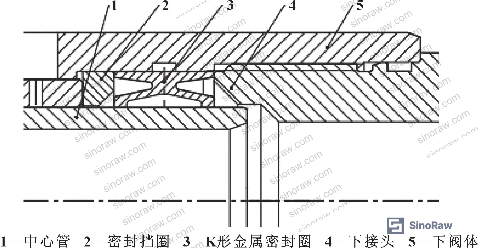
For buyers procuring fluid control components destined for intelligent well completion systems, subsea applications, or any downhole service environment, this analysis gives you a direct line to the structural parameters worth specifying — and the ones that aren’t worth fighting over.
Sealing performance in flow control valves is also closely related to upstream material and sealing & thermal component choices, both of which feed into total system reliability under rated pressure cycling.
K-Shaped Metal Seal Geometry: Which Parameters Actually Drive Performance #
This is where most buyers waste time. There are seven structural parameters that could plausibly affect K-ring sealing performance: interference fit (δ), cantilever thickness (t), cantilever length (l), lip length (a), cantilever outer arc radius (R3), cantilever internal angle (α), and cantilever inner arc radius (R2). Honestly, most procurement teams try to specify all seven — and that creates supplier confusion without adding measurable quality control value.
The orthogonal range analysis tells a cleaner story. For sealing surface contact pressure, the influence ranking from most to least significant is: lip length (D) > cantilever internal angle (F) > cantilever thickness (B) > cantilever length (C) > cantilever inner arc (G) > interference fit (A) > cantilever outer arc (E). The same top three — lip length, cantilever internal angle, cantilever thickness — dominate effective contact length as well, with range values of 0.733, 0.513, and 0.137 respectively, versus 0.083 for cantilever outer arc (the least influential parameter).
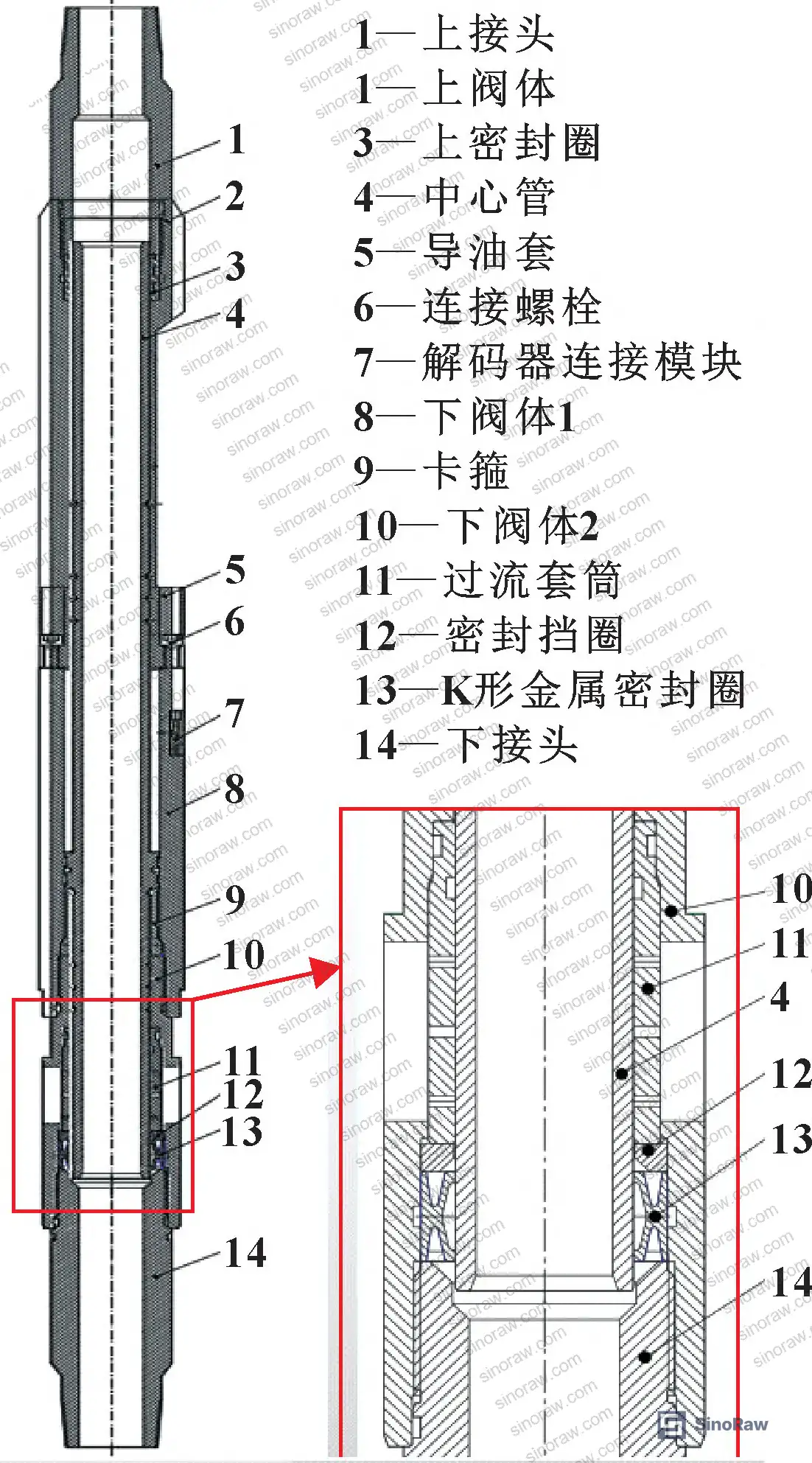
Interference fit and the two arc parameters contribute relatively little to either performance metric. Stop over-specifying them. Your quality hold point should be on the three dominant factors.
Comparison of structural parameter influence on K-ring sealing performance (orthogonal range analysis):
| Structural Parameter | Range R (Contact Pressure) | Range R (Effective Contact Length) | Influence Rank |
|---|---|---|---|
| Lip length (a) | 68.090 | 0.733 | 1st — dominant |
| Cantilever internal angle (α) | 52.175 | 0.513 | 2nd — significant |
| Cantilever thickness (t) | 44.824 | 0.137 | 3rd — moderate |
| Cantilever length (l) | 36.963 | 0.139 | 4th |
| Cantilever inner arc (R2) | 34.858 | 0.083 | 5th |
| Interference fit (δ) | 21.143 | 0.118 | 6th |
| Cantilever outer arc (R3) | 15.888 | 0.136 | 7th — minimal |
Can’t find a supplier meeting these specs? Submit your requirements and we’ll match you within 48 hours.
FEA Baseline Results and the Stress Distribution That Decides Seal Life #
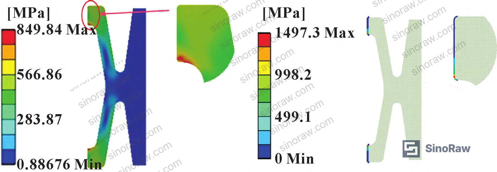
Under rated conditions — 40 MPa working pressure, 0.2 mm initial interference — the baseline K-ring model produced a maximum equivalent Mises stress of 849.84 MPa at the inner chamfer of the contact lip. That value sits comfortably below the GH4169 ultimate strength of 1355 MPa, so structural failure isn’t the immediate concern. What matters more is the contact pressure distribution.
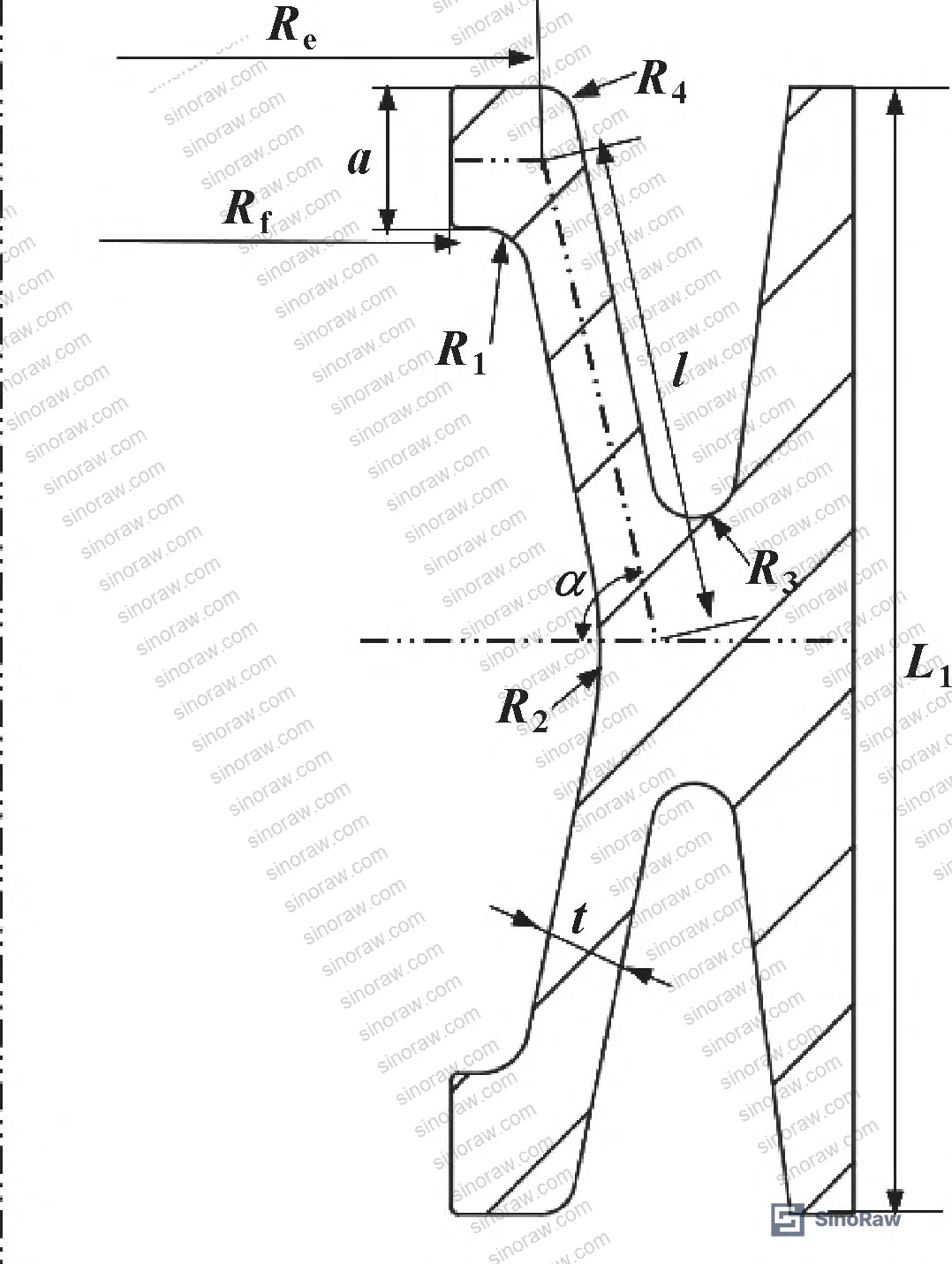
Maximum lip contact pressure at baseline was 1497.3 MPa. Average contact pressure was 211.78 MPa — more than three times the medium pressure of 40 MPa, which is the accepted minimum for reliable sealing. Both values satisfy the sealing criterion. But the ratio between peak and average contact pressure reveals the real issue: the contact band is not uniformly loaded. High peak-to-average ratios accelerate localized wear and fretting at the lip edge, which shortens service life under cyclic pressure conditions.
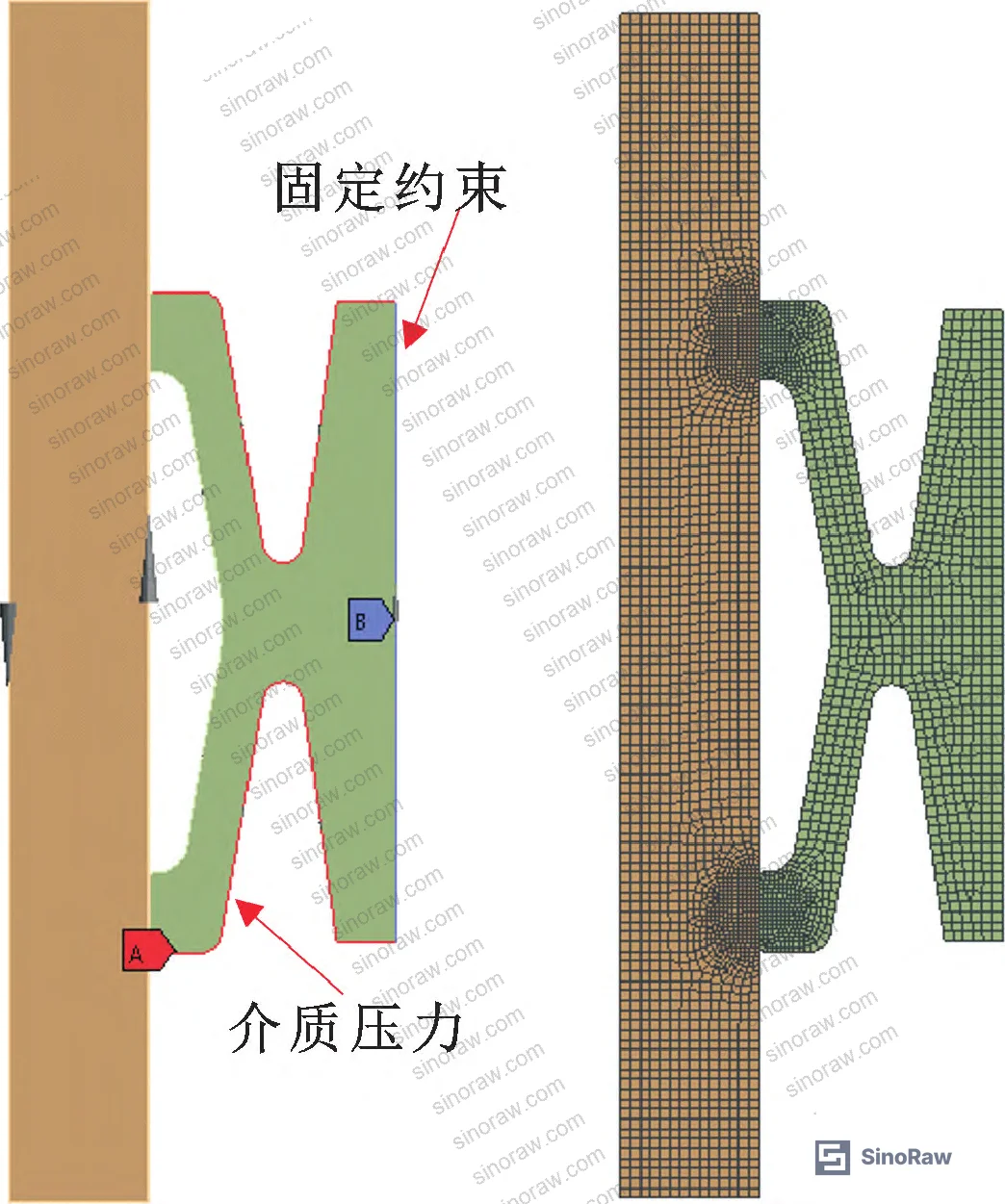
The effective contact length — defined as the proportion of the contact band where local pressure exceeds 3× medium pressure — was 1.405 mm in the baseline design. After structural optimization, it increased to 1.636 mm, a 14.73% improvement. That wider, more uniform contact band is worth more to long-term seal reliability than any incremental improvement in peak contact pressure.
In supplier qualification, we’ve reviewed FEA reports from multiple Chinese metallic seal manufacturers where the reported contact pressure looked acceptable on the surface, but effective contact length data was absent. Three of the six sample data packages reviewed showed contact bands barely exceeding the 3× medium pressure threshold across less than half the nominal contact width — a configuration that would likely fail within months under field pressure cycling, not years.
Most procurement teams don’t realize that the standard sealing acceptance criterion — contact pressure ≥ 3× medium pressure — applies to the average or peak value depending on which standard revision you’re working from. The more rigorous interpretation requires that threshold to be met across the full effective contact length, not just at the peak node. That distinction can cut your acceptable supplier list significantly.
For guidance on international standards governing sealing behavior in fluid systems under pressure cycling, IEC 62619:2022 Safety requirements for secondary lithium cells and batteries is not directly applicable here, but for high-integrity industrial fluid sealing applications, referencing ISO 12405-4 Electrically propelled road vehicles — Test specification for lithium-ion traction battery packs and systems alongside industry-specific pressure vessel codes provides useful context on validated FEA methodology acceptance criteria. For flow control component qualification in energy sector applications, IEEE 1679 Recommended Practice for the Characterization and Evaluation of Emerging Energy Storage Technologies offers a framework for evaluating simulation-to-test correlation requirements that translates well into sealing component qualification protocols.
Response Surface Optimization: What the Optimal Parameters Look Like #
The Box-Behnken design used 17 FEA runs across three factors (lip length, cantilever internal angle, cantilever thickness) at three levels each. The resulting quadratic regression models achieved R² values of 0.9321 for contact pressure, 0.9866 for effective contact length, and 0.9375 for maximum equivalent stress — all above 0.93, confirming strong predictive accuracy. Coefficient of variation across the three models was 6.29%, 3.76%, and 4.62% respectively, indicating tight fit.
The response surface equations show clear directional behavior worth knowing:
- Contact pressure decreases as lip length increases, and increases with both cantilever internal angle and thickness
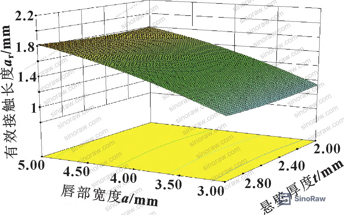
- Effective contact length increases with both lip length and cantilever internal angle; cantilever thickness has minimal effect on this metric
- Maximum equivalent stress increases with lip length; its relationship with cantilever thickness reverses direction at α = 80° (increases above 80°, decreases below 80°)
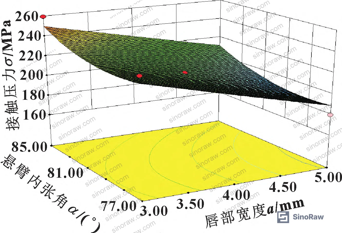
The Design-Expert 8.0 optimization module ran 11 iterations to generate candidate solutions. The top-ranked solution — maximum desirability value 0.854 — produced: lip length 3.80 mm, cantilever internal angle 84.43°, cantilever thickness 2.42 mm.
FEA validation of the optimized geometry against the response surface predictions showed prediction errors of 0.70% for contact pressure, 1.47% for effective contact length, and 1.44% for maximum equivalent stress — all well within engineering tolerance. That level of model-to-simulation agreement confirms the regression equations are reliable for design within the studied parameter ranges.
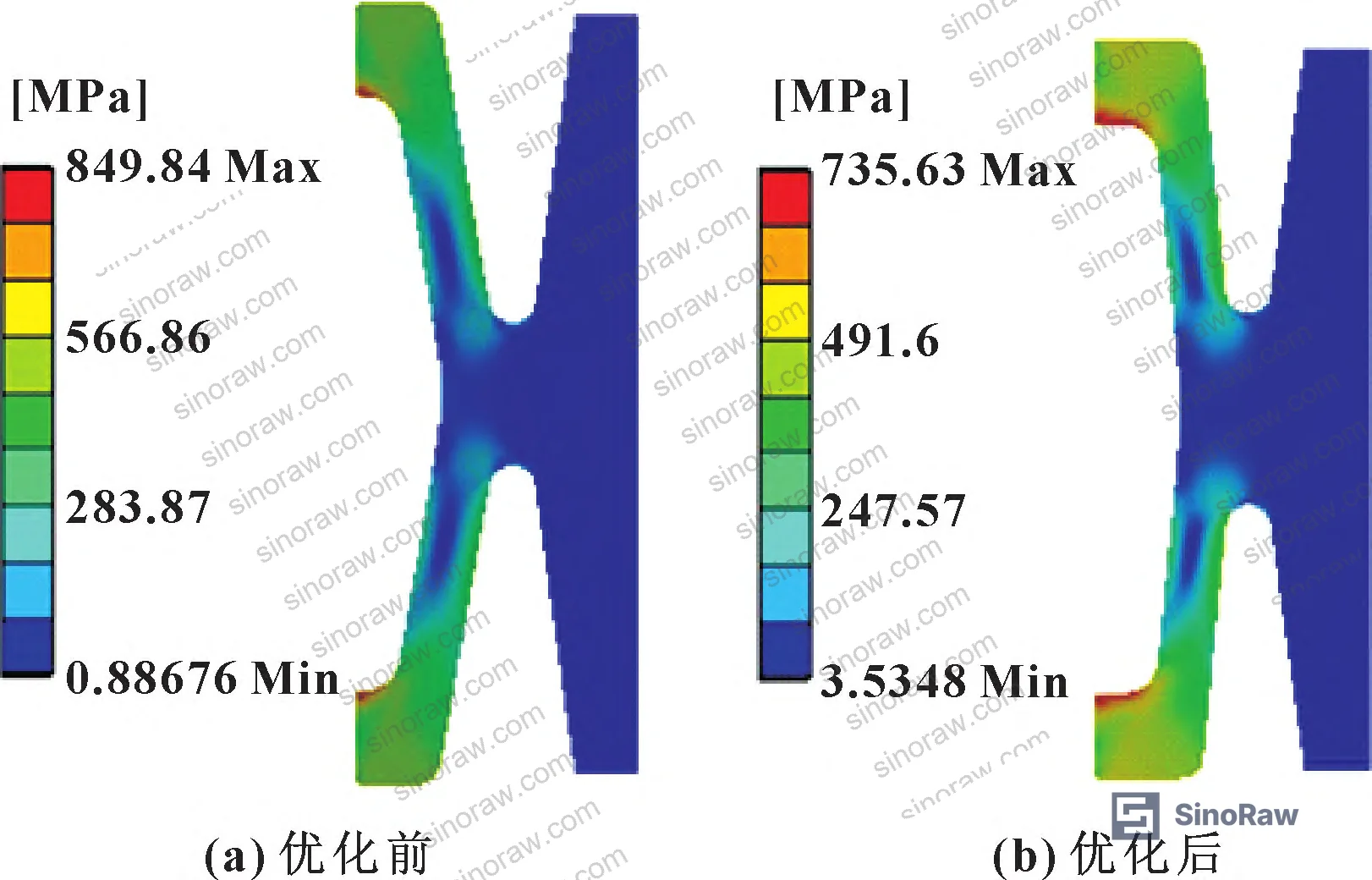
The before-and-after numbers are straightforward:
| Performance Metric | Baseline Value | Optimized Value | Change |
|---|---|---|---|
| Contact pressure (σ) | 214.720 MPa | 232.100 MPa (FEA) | +8.09% |
| Effective contact length (ar) | 1.405 mm | 1.612 mm (FEA) | +14.73% |
| Maximum equivalent stress (σmax) | 849.840 MPa | 735.630 MPa (FEA) | −13.44% |
| Lip length (a) | 4.00 mm | 3.80 mm | −5% |
| Cantilever internal angle (α) | 80.00° | 84.43° | +4.43° |
| Cantilever thickness (t) | 2.50 mm | 2.42 mm | −3.2% |
The key insight: all three improvements came from relatively modest geometric changes. No material upgrade. No manufacturing process change. Just tighter geometric specification of three parameters.
Practical Guidance for Buyers #
When you’re evaluating Chinese suppliers of K-shaped metal sealing rings for flow control valve applications, the most useful question isn’t about material certifications — it’s about whether the supplier has actually run FEA on their specific geometry under rated working conditions.
Ask for contact pressure distribution data, not just peak values. A seal can pass a peak contact pressure check while still having a narrow, poorly distributed contact band that will fail in field service. The target is an effective contact length where local pressure exceeds 3× medium pressure across the full sealing band — for a 40 MPa application, that means sustained contact pressure above 120 MPa across the contact zone.
The three parameters worth controlling tightly in your procurement specification are lip length (target range 3.0–5.0 mm, optimum near 3.80 mm for 40 MPa service), cantilever internal angle (target 75°–85°, optimum near 84°), and cantilever thickness (target 2.0–3.0 mm, optimum near 2.42 mm). Interference fit should be held at 0.2 mm single-sided for the rated working pressure.
We operate as a Guangzhou-based sourcing service connecting overseas procurement teams with verified Chinese manufacturers of components like these — we’re not making the rings, we’re qualifying the suppliers who do. If you need help shortlisting manufacturers who can demonstrate FEA-validated sealing geometry and GH4169 nickel alloy material traceability, we can run that pre-qualification process before you issue your RFQ.
Need help identifying qualified suppliers for K-shaped metal sealing rings for flow control valves? Talk to our sourcing team →
Supplier Qualification Questions #
- Can you provide FEA-calculated contact pressure distribution data for your K-ring design at 40 MPa working pressure, showing both peak contact pressure and average contact pressure across the sealing lip?
- What is the effective contact length in your current production geometry, defined as the contact band length where local pressure exceeds 3× medium pressure — and what lip length, cantilever internal angle, and cantilever thickness values produce that result?
- Your K-ring material spec — is it GH4169 nickel alloy or equivalent? Can you confirm elastic modulus ≥203 GPa and yield strength ≥1151 MPa with material test certificates, and what is your maximum equivalent stress at rated working pressure relative to the 1355 MPa ultimate strength limit?
- What initial interference fit (single-sided, in mm) does your standard K-ring geometry use, and how does your contact pressure respond when interference varies from the nominal 0.2 mm — do you have sensitivity data?
- What is the cantilever internal angle (α) in your production geometry, and can you demonstrate — via FEA or physical test — that maximum equivalent stress at the lip inner chamfer remains below material yield strength (1151 MPa) at the rated working pressure of 40 MPa?
Sourcing Checklist #
- ☐ Supplier can provide FEA contact pressure distribution data at 40 MPa showing average contact pressure ≥ 3× medium pressure (≥120 MPa) across the full sealing lip contact zone
- ☐ Effective contact length confirmed ≥1.60 mm for sealing rings in 40 MPa service, per FEA simulation or physical test measurement
- ☐ Maximum equivalent Mises stress at rated working pressure confirmed below material yield strength (≤1151 MPa for GH4169) with FEA report or third-party test data
- ☐ Material certification confirms GH4169 nickel alloy (or equivalent) with elastic modulus 203 GPa, Poisson’s ratio 0.3, yield strength 1151 MPa, ultimate strength 1355 MPa
- ☐ Lip length held within 3.0–5.0 mm range and cantilever internal angle within 75°–85° range per supplier’s geometric inspection records
- ☐ Interference fit specified at 0.2 mm single-sided for 40 MPa rated working pressure, with dimensional inspection data available
- ☐ Supplier can confirm cantilever thickness tolerance: target 2.0–3.0 mm with production Cpk ≥ 1.33 on this dimension
- ☐ Regression model or documented test data confirms contact pressure model R² ≥ 0.93, validating the supplier’s FEA methodology against physical test results
Key Specifications Table #
| Parameter | Recommended Value | Verification Method |
|---|---|---|
| Lip length (a) | 3.80 mm (range: 3.0–5.0 mm) | Dimensional inspection; CMM measurement |
| Cantilever internal angle (α) | 84.43° (range: 75°–85°) | CMM angular measurement; supplier drawing review |
| Cantilever thickness (t) | 2.42 mm (range: 2.0–3.0 mm) | Micrometer or CMM; Cpk ≥ 1.33 |
| Initial interference fit (δ) | 0.2 mm single-sided | Assembly inspection; FEA boundary condition confirmation |
| Average sealing contact pressure (σ) | ≥211.78 MPa at 40 MPa working pressure | FEA simulation report; physical press-fit contact test |
| Effective contact length (ar) | ≥1.60 mm (pressure > 3× medium pressure criterion) | FEA post-processing extraction; contact band marking test |
| Maximum equivalent stress (σmax) | ≤746 MPa (optimized); hard limit <1151 MPa (yield) | FEA Mises stress contour; strain gauge validation |
| Rated working pressure | 40 MPa | Hydrostatic pressure test per applicable pressure vessel standard |
Can’t find a supplier meeting these specs? Submit your requirements and we’ll match you within 48 hours.
References #
Data source: Structural Parameter Optimization of K-Shaped Metal Sealing Rings for Flow Control Valves Using Response Surface Methodology, N. Hou et al., Tribology International, 2025
Frequently Asked Questions #
What is a K-shaped metal sealing ring and why is it used in flow control valves?
A K-shaped metal sealing ring is a self-energizing lip-type metal seal designed for extreme service conditions — high temperature, high pressure, and corrosive media — where elastomeric seals fail. In flow control valves, particularly downhole or subsea intelligent completion systems, the K-ring lip makes radial contact with the center tube outer surface under interference fit. As medium pressure increases, it acts on the cantilevered arm and amplifies lip contact pressure, reinforcing the seal under load rather than allowing it to relax. This self-energizing behavior, combined with a high-temperature nickel alloy construction, makes it suitable for service conditions where conventional single-material seals cannot maintain integrity.
Which three structural parameters most significantly affect K-ring sealing performance?
Orthogonal range analysis across seven geometric variables consistently identifies lip length, cantilever internal angle, and cantilever thickness as the top three. Their range values for effective contact length were 0.733, 0.513, and 0.137 respectively — compared to 0.083 for the least influential parameter (cantilever outer arc). These three parameters should be the primary focus of both design specification and incoming inspection.
What does “effective contact length” mean and why does it matter more than peak contact pressure?
Effective contact length is the portion of the sealing lip contact band where local contact pressure exceeds three times the medium pressure. A seal can show an acceptable peak contact pressure while still having a narrow, poorly distributed contact zone — which creates stress concentrations, accelerates localized wear, and shortens service life. The optimized K-ring geometry increased effective contact length by 14.73% (from 1.405 mm to 1.636 mm) while only improving average contact pressure by 8.09%. That wider, more uniform contact band is the more reliable long-term performance indicator.
What material is used for K-shaped metal sealing rings in high-pressure downhole applications?
GH4169 nickel-based superalloy is the standard material for this application. It maintains good mechanical properties across a temperature range of −253°C to 650°C, with elastic modulus 203 GPa, yield strength 1151 MPa, ultimate strength 1355 MPa, and excellent corrosion resistance. The optimization study confirmed that even after parameter adjustment, the maximum equivalent stress at the lip (735.63 MPa in the optimized design) remains well below both yield and ultimate limits.
How accurate are response surface model predictions compared to actual FEA results?
Very accurate for this geometry. Validation showed prediction errors of 0.70% for contact pressure, 1.47% for effective contact length, and 1.44% for maximum equivalent stress between the regression model and direct FEA simulation results. The three response surface models achieved R² values of 0.9321, 0.9866, and 0.9375 with coefficient of variation below 6.3% across all three metrics — confirming the models are reliable for design optimization within the studied parameter ranges (lip length 3–5 mm, cantilever internal angle 75°–85°, cantilever thickness 2–3 mm).
Published by sinoraw.com Technical Team | Request a sourcing quote


